Table of Contents
Advertisement
Advertisement
Table of Contents

Related Manuals for MSI P965 NEO-F - Motherboard - ATX


Summary of Contents for MSI P965 NEO-F - Motherboard - ATX
- Page 1 P965Neo-F V2 Series MS-7235 (V2.X) Mainboard G52-72351XC...
-
Page 2: Copyright Notice
If a problem arises with your system and no solution can be obtained from the user’s manual, please contact your place of purchase or local distributor. Alternatively, please try the following help resources for further guidance. Visit the MSI website for FAQ, technical guide, BIOS updates, driver updates, and other information: http://www.msi.com.tw/program/service/faq/ faq/esc_faq_list.php... -
Page 3: Safety Instructions
Safety Instructions Always read the safety instructions carefully. Keep this User’s Manual for future reference. Keep this equipment away from humidity. Lay this equipment on a reliable flat surface before setting it up. The openings on the enclosure are for air convection hence protects the equip- ment from overheating. - Page 4 FCC-B Radio Frequency Interference Statement T h is eq uip men t h as been tested and found to c omply with the limits for a Class B digital device, pursuant to Part 15 of the FCC Rules. These limits are designed to provide reasonable protection against harmful interference in a residential installation.
- Page 5 WEEE (Waste Electrical and Electronic Equipment) Statement...
-
Page 8: Table Of Contents
Chapter 1 Getting started ..................1-1 Mainboard Specifications ................... 1-2 Mainboard Layout ....................1-4 Packing Checklist ....................1-4 MSI Special Feature .................... 1-6 Chapter 2 Hardware Setup ................... 2-1 Quick Components Guide ..................2-2 CPU (Central Processing Unit) ................2-2 Introduction to LGA 775 CPU .............. - Page 9 Chapter 3 BIOS Setup ..................... 3-1 Entering Setup ..................... 3-2 The Main Menu ..................... 3-4 Standard CMOS Features ................... 3-6 Advanced BIOS Features ................... 3-8 Advanced Chipset Features ................3-10 Integrated Peripherals ..................3-10 Power Management Setup ................3-12 PNP/PCI Configurations ..................3-17 Cell Menu ......................
-
Page 10: Chapter 1 Getting Started
Getting Started Chapter 1 Getting Started Thank you for choosing the P965Neo-F V2 Series (MS- 7235 v2.X) ATX mainboard. The P965Neo-F V2 Series mainboards are based on Intel P965 / G965 & ICH8 ® chipsets for optimal system efficiency. Designed to fit the advanc ed Intel Pentium 4 LG A775 s er ies ®... -
Page 11: Mainboard Specifications
- Supports 4 pin CPU Fan Pin-Header with Fan Speed Control - Supports EIST Technology - Supports Hyper-Threading (HT) Technology - Supports Intel Quad Core / Dual Core Technology up to 1066 MHz (For the latest information about CPU, please visit http://www.msi. com.tw/program/products/mainboard/mbd/pro_mbd_cpu_support.php) Supported FSB - 1066/ 800/ 533 MHz... - Page 12 Getting Started Connectors Back panel - 1 PS/2 mouse port - 1 PS/2 keyboard port - 1 VGA port (optional, for G965 only) - 1 serial port (COM1) - 1 parallel port supporting SPP/EPP/ECP mode - 4 USB 2.0 Ports - 1 LAN jack (10/100/1000) - 6 flexible audio jacks - 1 1394 port (optional)
-
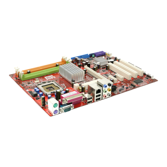
Page 13: Mainboard Layout
M S-7235 M ainboard Mainboard Layout SYSFAN1 Top : mouse Bottom: keyboard JPW1 Top : Parallel Port Bottom: COM portA VGA port (G965 only) Top:1394 (optional) Bottom: USB ports Inte l CPUFAN1 P 9 65 / G9 65 Top: LAN Jack Bottom: USB ports Line-In F71882FG... -
Page 14: Packing Checklist
Getting Started Packing Checklist MSI Driver/Utility CD SATA Cable MSI motherboard Standard Cable for Power Cable IDE Devices Back IO Shield User’s Guide * The pictures are for reference only. Your packing contents may vary depending on the model you purchased. -
Page 15: Msi Special Feature
M S-7235 M ainboard MSI Special Feature The Core Center is a new utility you can find in the CD-ROM disk. The utility is just like your PC doctor that can detect, view and adjust the PC hardware and system status during real time operation. - Page 16 Getting Started Left-wing: Current system status In the left sub-menu, you can configure the settings of FSB, Vcore, Memory Voltage and AGP Voltage by clicking the radio button next to each item and make it available (the radio button will be lighted as yellow when selected), use the “+” and “-” buttons to adjust, then click “OK”...
-
Page 17: Chapter 2 Hardware Setup
Hardware Setup Chapter 2 Hardware Setup This chapter provides you with the information about hardware setup procedures. While doing the installation, be careful in holding the components and follow the installation procedures. For some components, if you install in the wrong orientation, the components will not work properly. -
Page 18: Quick Components Guide
M S-7235 M ainboard Quick Components Guide JCASE1, p.2-14 JPW1, p.2-9 DDRII DIMMs, p.2-7 SYSFAN1, p.2-14 CPU, p.2-3 CPUFAN1, p.2-14 Back Panel I/O, p.2-10 ATXPWR1, p.2-9 JIR1, NBFAN1, p.2-19 p.2-14 PCI Express JSPI1, p.2-19 slots, p.2-21 SATA7, p.2-13 IDE1, p.2-12 SATA1~4, p.2-13 PCI Slots,... -
Page 19: Cpu (Central Processing Unit)
W hen you are installing the CPU, make sure to install the cooler to prevent overheating. If you do not have the CPU cooler, contact your dealer to purchase and install them before turning on the computer. For the latest information about CPU, please visit http://www.msi.com.tw/program/ products/mainboard/mbd/pro_mbd_cpu_support.php. Important 1. -
Page 20: Cpu & Cooler Installation
M S-7235 M ainboard CPU & Cooler Installation W hen you are installing the CPU, make sure the CPU has a cooler at- tached on the top to prevent overheating. If you do not have the cooler, contact your dealer to purchase and install them before turning on the computer. Meanwhile, do not forget to apply some silicon heat transfer compound on CPU before installing the heat sink/cooler fan for better heat dispersion. - Page 21 Hardware Setup Important 1. Confirm if your CPU cooler is firmly installed before turning on your system. 2. Do not touch the CPU socket pins to avoid damaging. 3. The availability of the CPU land side cover depends on your CPU packing. 5.
- Page 22 M S-7235 M ainboard 9. Press down the load lever lightly 10. Align the holes on the mainboard onto the load plate, and then se- with the heatsink. Push down the cure the lever with the hook under c ooler u nti l i ts f ou r c lip s g et retention tab.
-
Page 23: Dual Channel Memory Population Rules
Hardware Setup Memory The mainboard provides four 240-pin non-ECC DDRII 800/667/533 DIMM slots and supports up to 8GB system memory. For more information on compatible components, please visit http://www.msi.com.tw/ program/products/mainboard/mbd/pro_mbd_trp_list.php. DDRII 240-pin, 1.8V 64x2=128 pin 56x2=112 pin Single-Channel: All DIMMs in GREEN Dual-Channel: Channel A in GREEN;... -
Page 24: Installing Ddrii Modules
M S-7235 M ainboard Installing DDRII Modules 1. The memory module has only one notch on the center and will only fit in the right orientation. 2. Insert the memory module vertically into the DIMM slot. Then push it in until the golden finger on the memory module is deeply inserted in the DIMM slot. -
Page 25: Power Supply
Hardware Setup Power Supply ATX 24-Pin Power Connector: ATXPWR1 This connector allows you to connect an ATX 24-pin power supply. To connect the ATX 24-pin power supply, make sure the plug of the pin 13 power supply is inserted in the proper orientation and the pins are aligned. -
Page 26: Back Panel
M S-7235 M ainboard Back Panel L-In RS-Out L-Out CS-Out Parallel Port IEEE1394 M ou se (optional) USB Ports Keyboard VGA Port SS-Out Serial Port (G965 only) M ouse/Keyboard Connector The standard PS/2 mouse/keyboard DIN connector is for a PS/2 mouse/keyboard. - Page 27 Hardware Setup Audio Port Connectors These audio connectors are used for audio devices. You can differentiate the color of the audio jacks for different audio sound effects. Blue audio jack - Line In Green audio jack - Line Out, is a connector for speakers or headphones. Pink audio jack - Mic In, is a connector for microphones.
-
Page 28: Floppy Disk Drive Connector: Fdd1
M S-7235 M ainboard Connectors Floppy Disk Drive Connector: FDD1 This standard FDD connector supports 360K, 720K, 1.2M, 1.44M and 2.88M floppy disk types. FDD1 Hard Disk Connector: IDE1 The mainboard provides a one-channel Ultra ATA 133 bus Master IDE controller that supports PIO mode 0~4, Bus Master, and Ultra DMA 66/100/133 function. -
Page 29: Serial Ataii Connectors: Sata1/2/3/4/7
Hardware Setup Serial ATAII Connectors: SATA1/2/3/4/7 SATA1/2/3/4/7 are high-speed Serial ATAII interface ports. Each supports 2 genera- tion serial ATA data rates of 300MB/s and is fully compliant with Serial ATA 2.0 specifications. Each Serial ATAII connector can connect to 1 SATA device. SATA1/2/3/4/7 Pin Definition SATA7 SATA7... -
Page 30: Fan Power Connectors: Cpufan1, Nbfan1, Sysfan1
M S-7235 M ainboard Fan Power Connectors: CPUFAN1, NBFAN1, SYSFAN1 The fan power connectors support system cooling fan with +12V. W hen connecting the wire to the connectors, always take note that the red wire is the positive and should be connected to the +12V, the black wire is Ground and should be connected to GND. -
Page 31: Cd-In Connector: Cd_In1
Hardware Setup SPDIF-Out Connector: JSPD1 (2pin / 3pin optional) This connector is used to connect SPDIF (Sony & Philips Digital Interconnect Format) interface for digital audio transmission. 2pin header is used to connect to the HDMI graphics card. 3pin header is used to connect to the SPDIF optional bracket. (optional) JSPD1 SPDF0... -
Page 32: Front Panel Connectors: Jfp1/Jfp2
M S-7235 M ainboard Front Panel Connectors: JFP1/JFP2 The mainboard provides two front panel connectors for electrical connection to the front panel switches and LEDs. The JFP1 is compliant with Intel Front Panel I/O ® Connectivity Design Guide. Power Power Switch Speaker Power... -
Page 33: Ieee 1394 Connectors: J1394_1(Optional)
Hardware Setup IEEE 1394 Connectors: J1394_1(Optional) The mainboard provides IEEE1394 pinheaders that allow you to connect IEEE 1394 ports via an external IEEE1394 bracket (optional). Pin Definition SIGNAL SIGNAL TPA+ TPA- Ground Ground TPB+ TPB- J1394_1 Cable power Cable power Key (no pin) Ground Connected to J1394_1... -
Page 34: Front Usb Connectors: Jusb2, Jusb3, Jusb4
M S-7235 M ainboard Front USB Connectors: JUSB2, JUSB3, JUSB4 The mainboard provides three USB 2.0 pinheaders (optional USB 2.0 bracket available) that are compliant with Intel I/O Connectivity Design Guide. USB 2.0 technology ® increases data transfer rate up to a maximum throughput of 480Mbps, which is 40 times faster than USB 1.1, and is ideal for connecting high-speed USB interface peripherals such as USB HDD, digital cameras, M P3 players, printers, mo- dems and the like. -
Page 35: Irda Infrared Module Header: Jir1
Hardware Setup IrDA Infrared Module Header: JIR1 The connector allows you to connect to IrDA Infrared module. You must configure the setting through the BIOS setup to use the IR function. JIR1 is compliant with Intel ® Front Panel I/O Connectivity Design Guide. Pin Definition Signal IRRX... -
Page 36: Jumpers
M S-7235 M ainboard Jumpers Clear CMOS Jumper: JBAT1 There is a CMOS RAM onboard that has a power supply from external battery to keep the data of system configuration. With the CMOS RAM, the system can automatically boot OS every time it is turned on. If you want to clear the system configuration, set the JBAT1 (Clear CMOS Jumper ) to clear data. -
Page 37: Slots
Hardware Setup Slots PCI (Peripheral Component Interconnect) Express Slots PCI Express architecture provides a high performance I/O infrastructure for Desktop Platforms with transfer rates starting at 2.5 Giga transfers per second over a PCI Express x1 lane for Gigabit Ethernet, TV Tuners, 1394 controllers, and general pur- pose I/O. -
Page 38: Pci Interrupt Request Routing
M S-7235 M ainboard Important When adding or removing expansion cards, make sure that you unplug the power supply first. Meanwhile, read the documentation for the expansion card to configure any necessary hardware or software settings for the expansion card, such as jumpers, switches or BIOS configuration. PCI Interrupt Request Routing The IRQ, acronym of interrupt request line and pronounced I-R-Q, are hardware lines over which devices can send interrupt signals to the microprocessor. -
Page 39: Chapter 3 Bios Setup
BIOS Setup Chapter 3 BIOS Setup This chapter provides information on the BIOS Setup program and allows you to configure the system for optimum use. You may need to run the Setup program when: ² An error message appears on the screen during the system booting up, and requests you to run SETUP. -
Page 40: Entering Setup
M S-7235 M ainboard Entering Setup Power on the computer and the system will start POST (Power On Self Test) process. W hen the message below appears on the screen, press <DEL> key to enter Setup. Press DEL to enter SETUP If the message disappears before you respond and you still wish to enter Setup, restart the system by turning it OFF and On or pressing the RESET button. -
Page 41: Control Keys
BIOS Setup Control Keys Move to the previous item < > Move to the next item < > Move to the item in the left hand < > Move to the item in the right hand < > Select the item <Enter>... -
Page 42: The Main Menu
M S-7235 M ainboard The Main Menu Standard CM OS Features Use this menu for basic system configurations, such as time, date etc. Advanced BIOS Features Use this menu to setup the items of AWARD special enhanced features. ® Advanced Chipset Features Use this menu to change the values in the chipset registers and optimize your system’s performance. - Page 43 BIOS Setup Load Fail-Safe Defaults Use this menu to load the default values set by the mainboard manufacturer. Load Optimized Defaults Use this menu to load the default values set by the mainboard manufacturer specifi- cally for optimal performance of the mainboard. BIOS Setting Password Use this menu to set the password for BIOS.
-
Page 44: Standard Cmos Features
M S-7235 M ainboard Standard CMOS Features The items in Standard CMOS Features Menu includes some basic setup items. Use the arrow keys to highlight the item and then use the <+> or <-> keys to select the value you want in each item. Date (MM:DD:YY) This allows you to set the system to the date that you want (usually the current date). - Page 45 BIOS Setup IDE Primary/Secondary M aster/Slave Selecting “manual” lets you set the remaining fields on this screen. Selects the type of fixed disk. “User Type” will let you select the number of cylinders, heads, etc. Access M ode Choose the access mode forthis hard disk Floppy A This item allows you to set the type of floppy drive installed.
-
Page 46: Advanced Bios Features
M S-7235 M ainboard Advanced BIOS Features Full Screen LOGO Display This item enables you to show the company logo on the bootup screen. Settings are: [Enabled] Shows a still image (logo) on the full screen at boot. [Disabled] Shows the POST messages at boot. Quick Booting Setting the item to [Enabled] allows the system to boot within 5 seconds since it will skip some check items. - Page 47 BIOS Setup Important Enabling the functionality of Hyper-Threading Technology for your computer system requires ALL of the following platform Components: ® ® * CPU: An Intel Pentium 4 Processor with HT Technology; ® * Chipset: An Intel Chipset that supports HT Technology; * BIOS: A BIOS that supports HT Technology and has it enabled;...
-
Page 48: Advanced Chipset Features
M S-7235 M ainboard Advanced Chipset Features Important Change these settings only if you are familiar with the chipset. Configure DRAM Timing by SPD Selects whether DRAM timing is controlled by the SPD (Serial Presence Detect) EEPROM on the DRAM module. Setting to [Enabled] enables DRAM timings and the following related items to be determined by BIOS based on the configurations on the SPD. -
Page 49: Integrated Peripherals
BIOS Setup Integrated Peripherals USB Functions This setting is used to enable/disable the onboard USB host controller. USB Legacy Support Set to [Enabled] if your need to use any USB 1.1/2.0 device in the operating system that does not support or have any USB 1.1/2.0 driver installed, such as DOS and SCO Unix. - Page 50 M S-7235 M ainboard SATA#1 Configuration This item allows you to configurare IDE device mode. [Compatible] If Compatible selected, Legacy IDE Channels will only use IRQ14 and IRQ15. [Enhanced] If Enhanced selected, you could use the other IRQs (except IRQ14 and IRQ15). I/O Devices Press <Enter>...
-
Page 51: Power Management Setup
BIOS Setup Power Management Setup Important S3-related functions described in this section are available only when your BIOS supports S3 sleep mode. ACPI Function This item is to activate the ACPI (Advanced Configuration and Power Management Interface) Function. If your operating system is ACPI-aware, such as Windows 98SE/ 2000/ME/XP, select [Enabled]. - Page 52 M S-7235 M ainboard Re-Call VGA BIOS from S3 W hen ACPI Standby State is set to [S3/STR], users can select the options in this field. Selecting [Yes] allows BIOS to call VGABIOS to initialize the VGA card when system wakes up (resumes) from S3 sleep state. The system resume time is short- ened when you disable the function, but system will need an AGP driver to initialize the VGA card.
- Page 53 BIOS Setup Resume By PCI Device (PM E) The item specifies how the system will be awakened from power saving mode when input signal of the PCI is detected Resume by RTC Alarm This is used to enable or disable the feature of booting up the system on a scheduled time/date from the S3, S4, and S5 power off state.
-
Page 54: Pnp/Pci Configurations
M S-7235 M ainboard PNP/PCI Configurations This section describes configuring the PCI bus system and PnP (Plug & Play) feature. PCI, or Peripheral Component Interconnect, is a system which allows I/O devices to operate at speeds nearing the speed the CPU itself uses when communicating with its special components. - Page 55 BIOS Setup PCI Slot1/2 IRQ These items specify the IRQ line for each PCI slot. IRQ Resources Setup Press <Enter> to enter the submenu: Important IRQ (Interrupt Request) lines are system resources allocated to I/O devices. When an I/O device needs to gain attention of the operating system, it signals this by causing an IRQ to occur.
- Page 56 M S-7235 M ainboard H/W Monitor This section shows the status of your CPU, fan, overall system status, etc. Monitor function is available only if there is hardware monitoring mechanism onboard. Chassis Intrusion The field enables or disables the feature of recording the chassis intrusion status and issuing a warning message if the chassis is once opened.
-
Page 57: Cell Menu
D.O.T Control This item allows you to select CPU, PCIE or both of them to be controled by D.O.T (Dynamic Overclocking Technology). D.O.T is the automatic overclocking function, included in the MSI ’s newly developed CoreCell Technology. It is designed to detect the load balance of CPU while running programs, and to adjust the best CPU frequency automatically. - Page 58 M S-7235 M ainboard CPU Ratio CMOS Setting This item allows you to adjust the CPU ratio. It is available only when the processor supports this function. Adjusted CPU CLOCK Indicates the adjusted CPU clock. CPU Vcore Indicates the CPU core voltage (Vcore). Add CPU Voltage (V) Adjusting the CPU voltage can increase the CPU speed.
-
Page 59: Cpu And Memory Clock Overclocking
CPU FSB Frequency are the items for you to overclock the CPU and the Memory. Please refer to the descriptions of these fields for more information. MSI Reminds You... 1. CPU Clock = FSB Frequency * Adjust CPU Ratio 2. Memory speed = FSB Frequency x Memory Ratio x Double Data Rate 3. -
Page 60: Load Optimized Defaults
M S-7235 M ainboard Load Optimized Defaults The two options on the main menu allow users to restore all of the BIOS settings to the default Fail-Safe or Optimized values. The Optimized Defaults are the default values set by the mainboard manufacturer specifically for optimal performance of the mainboard. -
Page 61: Bios Setting Password
BIOS Setup BIOS Setting Password W hen you select this function, a message as below will appear on the screen: Type the password, up to 6 characters in length, and press <Enter>. The password typed now will replace any previously set password from CMOS memory. You will be prompted to confirm the password. -
Page 62: Appendix A Realtek Alc888 Audio
Appendix A Realtek ALC888 Audio The Realtek ALC888 provides 10-channel DAC that si- multaneously supports 7.1 sound playback and 2 chan- nels of independent s tereo s ound output (multiple streaming) through the Front-Out-Left and Front-Out- Right channels. -
Page 63: Installation For Windows 2000/Xp
M S-7235 M ainboard Installing the Realtek HD Audio Driver You need to install the driver for Realtek ALC888 codec to function properly before you can get access to 2-, 4-, 6-, 8- channel or 7.1+2 channel audio operations. Follow the procedures described below to install the drivers for different operating systems. - Page 64 Realtek ALC888 Audio 3. Click Next to install the Realtek High Definition Audio Driver. Click here 4. Click Finish to restart the system. S el ec t t hi s option Click here...
-
Page 65: Software Configuration
M S-7235 M ainboard Software Configuration After installing the audio driver, you are able to use the 2-, 4-, 6- or 8- channel audio feature now. Click the audio icon from the system tray at the lower-right corner of the screen to activate the HD Audio Configuration. It is also available to enable the audio driver by clicking the Realtek HD Audio M anager from the Control Panel. -
Page 66: Sound Effect
Realtek ALC888 Audio Sound Effect Here you can select a sound effect you like from the Environment list. Environment Simulation You will be able to enjoy different sound experience by pulling down the arrow, totally 23 kinds of sound effect will be shown for selection. Realtek HD Audio Sound Manager also provides five popular settings “Stone Corridor”, “Bathroom”, “Sewer pipe”, “Arena”... - Page 67 M S-7235 M ainboard Equalizer Selection Equalizer frees users from default settings; users may create their owned preferred settings by utilizing this tool. 10 bands of equalizer, ranging from 100Hz to 16KHz. Save Reset The settings are saved 10 bands of equalizer permanently for future would go back to the de- fault setting...
- Page 68 Realtek ALC888 Audio Frequently Used Equalizer Setting Realtek recognizes the needs that you might have. By leveraging our long experience at audio field, Realtek HD Audio Sound Manager provides you certain optimized equal- izer settings that are frequently used for your quick enjoyment. [How to Use It] Other than the buttons “Pop”...
-
Page 69: Mixer
M S-7235 M ainboard Mixer In the Mixer part, you may adjust the volumes of the rear and front panels individually. 1. Adjust Volume You can adjust the volume of the speakers that you pluged in front or rear panel by select the Realtek HD Audio rear output or Realtek HD Audio front output items. - Page 70 Realtek ALC888 Audio W hen you are playing the first audio source (for example: use W indows Media Player to play DVD/VCD), the output will be played from the rear panel, which is the default setting. Then you must to select the Realtek HD Audio front output from the scroll list first, and use a different program to play the second audio source (for example: use Winamp to play MP3 files).
- Page 71 M S-7235 M ainboard 3. Playback control Playback device This function is to let you freely decide which ports to Tool Mute output the sound. And this is essential when multi- streaming playback enabled. - Realtek HD Audio Rear Output - Realtek HD Audio Front Output M u te You may choose to mute single or multiple volume controls or to completely mute...
- Page 72 Realtek ALC888 Audio 4. Recording control Recording device Tool Mute -Back Line in/Mic, Front Lin in -Realtek HD Audio Input M u te You may choose to mute single or multiple volume controls or to completely mute sound input. Tool - Show the following volume controls This is to let you freely decide which volume control items to be displayed.
-
Page 73: Audio I/O
M S-7235 M ainboard Audio I/O In this tab, you can easily configure your multi-channel audio function and speakers. You can choose a desired multi-channel operation here. a. Headphone for the common headphone b. 2CH Speaker for Stereo-Speaker Output c. 4CH Speaker for 4-Speaker Output d. - Page 74 Realtek ALC888 Audio Connector Settings Click to access connector settings. Disable front panel jack detection (option) Find no function on front panel jacks? Please check if front jacks on your system are so-called AC’97 jacks. If so, please check this item to disable front panel jack detection. M ute rear panel output when front headphone plugged in.
- Page 75 M S-7235 M ainboard S/PDIF Short for Sony/Philips Digital Interface, a standard audio file transfer format. S/PDIF allows the transfer of digital audio signals from one device to another without having to be converted first to an analog format. Maintaining the viability of a digital signal prevents the quality of the signal from degrading when it is converted to analog.
- Page 76 Realtek ALC888 Audio Test Speakers You can select the speaker by clicking it to test its functionality. The one you select will light up and make testing sound. If any speaker fails to make sound, then check whether the cable is inserted firmly to the connector or replace the bad speakers with good ones.
-
Page 77: Microphone
M S-7235 M ainboard Microphone In this tab you may set the function of the microphone. Select the Noise Suppres- sion to remove the possible noise during recording, or select Acoustic Echo Cancelltion to cancel the acoustic echo druing recording. Acoustic Echo Cancelltion prevents playback sound from being recorded by mi- crophone together with your sound. -
Page 78: 3D Audio Demo
Realtek ALC888 Audio 3D Audio Demo In this tab you may adjust your 3D positional audio before playing 3D audio applica- tions like gaming. You may also select different environment to choose the most suitable environment you like. A-17... -
Page 79: Information
M S-7235 M ainboard Information In this tab it provides some information about this HD Audio Configuration utility, including Audio Driver Version, DirectX Version, Audio Controller & Audio Codec. You may also select the language of this utility by choosing from the Language list. Also there is a selection Show icon in system tray. -
Page 80: Hardware Setup
Realtek ALC888 Audio Hardware Setup Connecting the Speakers W hen you have set the Multi-Channel Audio Function mode properly in the software utility, connect your speakers to the correct phone jacks in accordance with the setting in software utility. n 2-Channel M ode for Stereo-Speaker Output Refer to the following diagram and caption for the function of each phone jack on the back panel when 2-Channel Mode is selected. - Page 81 M S-7235 M ainboard n 4-Channel M ode for 4-Speaker Output Back Panel Description: Connect two speakers to back panel’s Line Out connector and two speakers to the real-chan- nel Line Out connector. 4-Channel Analog Audio Output Line In Line Out (Front channels) Line Out (Rear channels) Line Out (Center and Subwoofer channel, but no functioning in this mode) Line Out (Side Surround channels, but no functioning in this mode)
- Page 82 Realtek ALC888 Audio n 6-Channel M ode for 6-Speaker Output Back Panel Description: Connect two speakers to back panel’s Line Out connector, two speakers to the rear-channel Line out connec tor and two s p e a k e r s t o t h e c e n t e r / subwoofer-channel Line Out 6-Channel Analog Audio Output connector.
- Page 83 M S-7235 M ainboard n 8-Channel M ode for 8-Speaker Output Description: Connect two speakers to back panel’s Line Out connector, two speakers to the rear-channel Line out connector, two speak- ers to the center/subwoofer- channel Line Out connector and 8-Channel Analog Audio Output two speakers to the side-chan- nel Line Out connector.