EP0138489A1 - Apparatus and methods for treating cells with radiation - Google Patents
Apparatus and methods for treating cells with radiation Download PDFInfo
- Publication number
- EP0138489A1 EP0138489A1 EP84306667A EP84306667A EP0138489A1 EP 0138489 A1 EP0138489 A1 EP 0138489A1 EP 84306667 A EP84306667 A EP 84306667A EP 84306667 A EP84306667 A EP 84306667A EP 0138489 A1 EP0138489 A1 EP 0138489A1
- Authority
- EP
- European Patent Office
- Prior art keywords
- tube
- radiation source
- cells
- chamber
- radiation
- Prior art date
- Legal status (The legal status is an assumption and is not a legal conclusion. Google has not performed a legal analysis and makes no representation as to the accuracy of the status listed.)
- Granted
Links
Images


Classifications
-
- A—HUMAN NECESSITIES
- A61—MEDICAL OR VETERINARY SCIENCE; HYGIENE
- A61M—DEVICES FOR INTRODUCING MEDIA INTO, OR ONTO, THE BODY; DEVICES FOR TRANSDUCING BODY MEDIA OR FOR TAKING MEDIA FROM THE BODY; DEVICES FOR PRODUCING OR ENDING SLEEP OR STUPOR
- A61M1/00—Suction or pumping devices for medical purposes; Devices for carrying-off, for treatment of, or for carrying-over, body-liquids; Drainage systems
- A61M1/36—Other treatment of blood in a by-pass of the natural circulatory system, e.g. temperature adaptation, irradiation ; Extra-corporeal blood circuits
- A61M1/3681—Other treatment of blood in a by-pass of the natural circulatory system, e.g. temperature adaptation, irradiation ; Extra-corporeal blood circuits by irradiation
-
- A—HUMAN NECESSITIES
- A61—MEDICAL OR VETERINARY SCIENCE; HYGIENE
- A61M—DEVICES FOR INTRODUCING MEDIA INTO, OR ONTO, THE BODY; DEVICES FOR TRANSDUCING BODY MEDIA OR FOR TAKING MEDIA FROM THE BODY; DEVICES FOR PRODUCING OR ENDING SLEEP OR STUPOR
- A61M1/00—Suction or pumping devices for medical purposes; Devices for carrying-off, for treatment of, or for carrying-over, body-liquids; Drainage systems
- A61M1/36—Other treatment of blood in a by-pass of the natural circulatory system, e.g. temperature adaptation, irradiation ; Extra-corporeal blood circuits
- A61M1/3621—Extra-corporeal blood circuits
- A61M1/3622—Extra-corporeal blood circuits with a cassette forming partially or totally the blood circuit
- A61M1/36226—Constructional details of cassettes, e.g. specific details on material or shape
- A61M1/362262—Details of incorporated reservoirs
-
- A—HUMAN NECESSITIES
- A61—MEDICAL OR VETERINARY SCIENCE; HYGIENE
- A61M—DEVICES FOR INTRODUCING MEDIA INTO, OR ONTO, THE BODY; DEVICES FOR TRANSDUCING BODY MEDIA OR FOR TAKING MEDIA FROM THE BODY; DEVICES FOR PRODUCING OR ENDING SLEEP OR STUPOR
- A61M1/00—Suction or pumping devices for medical purposes; Devices for carrying-off, for treatment of, or for carrying-over, body-liquids; Drainage systems
- A61M1/36—Other treatment of blood in a by-pass of the natural circulatory system, e.g. temperature adaptation, irradiation ; Extra-corporeal blood circuits
- A61M1/3681—Other treatment of blood in a by-pass of the natural circulatory system, e.g. temperature adaptation, irradiation ; Extra-corporeal blood circuits by irradiation
- A61M1/3683—Other treatment of blood in a by-pass of the natural circulatory system, e.g. temperature adaptation, irradiation ; Extra-corporeal blood circuits by irradiation using photoactive agents
Definitions
- This invention relates to the field of treating cells with radiation and specifically relates to the extracorporeal treatment of blood cells with U.V. radiation.
- lymphocytes a number of human disease states may be characterized by the overproduction of certain types of leukocytes, including lymphocytes, in comparison to other populations of cells which normally comprise whole blood. Excessive lymphocyte populations result in numerous adverse affects to the patients including the functional impairment of bodily organs eventually resulting in fatality.
- U.S. Patent No. 4,321,919 to Edelson describes a method for treating whole blood whereby such populations may be decreased.
- the method comprises treating the whole blood with dissolved psoralen of a type capable of forming photoadducts with DNA in the presence of U.V.A. radiation in the range of about 320 to 400 nanometers.
- the covalent bonding that results between the psoralen and the lymphocyte nucleic acid results in lymphocyte metabolic inhibition of the thusly treated cells. These cells are then returned to the patient.
- the present invention be simple to produce, and be capable of use by persons having a minimal level of training.
- the sample is passed around a plurality of fibers which optically relay the radiation from radiation source.
- these devices require that the fiber optics function very poorly so that the radiation is "lost" through the walls of the fibers thereby irradiating the cells.
- such systems are characterized by inefficient energy coupling thereby requiring very large and expensive radiation sources.
- the fluorescent black light source typically of tubular shape, is coaxially mounted in a tube of larger diameter, the ends of said outer tube being sealed with the radiation source.
- the outer tube is also provided with an inlet for receiving the cells to be irradiated and an outlet for discharging irradiated cells.
- a second outer tube of even larger diameter is coaxially mounted on the previously described device, its ends also in sealing communicating with the first outer tube.
- the second tube further comprises inlet and outlet means for receiving and discharging respectively cells to be irradiated.
- the chamber formed by the inner tube in sealing arrangement with the radiation source serves as a cooling chamber for reducing the heating effects of the bulb.
- a plurality of the previously described tubes are arranged to form a cassette which is preferably disposable.
- Flow takes place serially through each of the described tubular arrangements, preferably in a serpentine manner whereby each tubular apparatus is preferably held vertically and the predominant blood flow therethrough is in a vertical fashion whereby air bubbles and the like are efficaciously flushed out.
- the embodiment further provides for an inlet and outlet of blood at one end of the cassette and specifically, provides for blood inlet to be ideally positioned at the bottom most portion of the first tubular apparatus.
- the blood outlet advantageously communicates with the top of the last most cylindrical irradiating apparatus.
- body cells to be treated by irradiation with the aforedescribed device are removed from the body, passed through the chamber surrounding the radiation source, and then returned to the body.
- Such treatment may also involve contacting the cells to be irradiated with a compound, such as those available in the psoralen class, which is activated upon radiation from the light source.
- Activated as used herein means that the compound has substantially no effect prior to irradiation, and following irradiation affects the treated cells in a distinguishable and detectable manner.
- a distinguishable and detectable manner may include for instance, the disruption of membrane integrity, the alteration of DNA within the cell, and the like resulting in the substantial loss of effectiveness or viability of the thusly treated cell.
- such a light source 10 is shown with tubes 11 and 13 coaxially mounted thereon.
- the inner tube 11 is preferably provided with spacer rings 16 mounted on the end thereof in order to maintain coaxial alignment with tube 10.
- Permanent sealing connection may be made by application of a suitable sealing or cementing material such as the class of epoxy adhesives or solvents such as methylene chloride, particu- lary useful for "welding" various classes of plastics together.
- the inner tube is provided with orifices 12 permitting the free flow of convection currents through the chamber thereby cooling the light source 10.
- any suitable means such as forced air and the like.
- inner tube 11 is made from a substantially U.V. transparent material such as acrylic, cellulose triacetate or a suitable rigid PVC. Based on cost and availability, as well as U.V. tranparen- cy, acrylic tends to be the most preferred material and accordingly, is ideally employed in the best embodiment.
- a substantially U.V. transparent material such as acrylic, cellulose triacetate or a suitable rigid PVC. Based on cost and availability, as well as U.V. tranparen- cy, acrylic tends to be the most preferred material and accordingly, is ideally employed in the best embodiment.
- an outer tube 13 is coaxially mounted onto the inner tube 11 advantageously by means of spacers 15.
- the mounting with the spacers 15 is accomplished in a sealing fashion typically by the application of a suitable solvent for chemically "welding" the outer tube 13, the spacer 15, and the inner tube 11 together.
- Outer tube 13 has further mounted thereon inlet and outlet 14 for receiving and discharging respectively the fluid sample to be irradiated.
- these inlets 14 are Luer type connectors.
- spacers 15 have a protruding "finger” type projection which is preferably disposed on the opposite wall from the inlet 14 and outlet 14. Such a projection advantageously reduces stagnant fluid volumes which would otherwise accumulate in that location.
- a projection may take the form of virtually any shape and, if desired, may be eliminated all together.
- FIG. 3 depicts another embodiment of the instant invention wherein a single chamber is used formed by the tube 11 in coaxial orientation with bulb 10 with the ends thereof sealed with a suitable material such as epoxy 17.
- a suitable material such as epoxy 17.
- Tube 11 is outfitted with/inlet and outlets 14 for receiving and discharging the fluid sample.
- Orientation of flow within the chamber is ⁇ not important and may be in either direction, however, if a plurality of devices of either the type shown in FIG. 1 or FIG. 3 are employed such as shown in FIG. 4, they are preferably aligned in a vertical fashion and flow is arranged to proceed from bottom to top. Even if a single device is employed, this is the preferred flow arrangement for eliminating air bubbles which might otherwise become trapped in an alternative arrangement.
- FIG. 4 shows the most preferred embodiment referred to herein as a cassette.
- the cassette employs a plurality of irradiating chambers 20 each of which is substantially similar in structure to the embodiment shown in FIG. 1.
- the ideal arrangement has six such irradiating chambers 20, however, more or less such chambers may be employed, subject only to the constraints of practical construction and ease of handling. It will be readily understood, of course, that increasing the number of irradiation tubes and forcing the blood to flow through each of them, accordingly increases the amount of irradiation to the fluid flowing therethrough.
- blood is communicated to the irradiating chamber 20 through inlet 21 which may be either a Luer lock or simply an inlet pipe to which a tubing set may be attached by any suitable means such as solvent welding and the like.
- the fluid to be irradiated then flows in a generally upward direction and then downwardly through cross connecting means 22 which may comprise a flexible or inflexible tubing connecting chamber outlet 23 to chamber inlet 24 of the next irradiation chamber.
- cross connecting means 22 may comprise a flexible or inflexible tubing connecting chamber outlet 23 to chamber inlet 24 of the next irradiation chamber.
- each irradiation chamber 20 has tabs 29 holding the irradiation lamp 25 in place within the irradiation chamber. The openings between tabs in combination with inner wall 26 allow the formation of an. air space surrounding the lamp 25 which freely communicates with the atmosphere thereby providing cooling in much the same manner as obtained from the interior cooling chamber formed by tube 11 in FIG. 2.
- FIGURE 5 depicts the preferred embodiment of the blood treatment center 30 which employs the cassette of' Figure 4 in sliding drawer 37.
- the flow of heparin or other clot preventing solution through pump 31 via a tubing set (not shown) and the flow of blood through pump 32 from centi- fuge 33 is controlled by clamps 36A, B and C in turn con- ' trolled by control panel 39.
- the centrifuge 33 is a continuous flow type whereby the operator, by viewing through port 34, determines when a leukocyte rich portion of whole blood is obtained. All solutions are collected in bags (not shown) which hang beside internal access panels 38. After treatment, treated and nontreated blood portions are hung on drip stand 35 and reinfused into the patient.
- a device as that depicted in FIG. 3, having ends sealed with a combination O ring and epoxy material was employed with a Sylvania F8T5/BLB Lamp.
- a simple recirculating system was constructed comprising a flexible bag for holding the blood and communicating with inlet located at the bottom of the vertically arranged device. The blood was permitted to flow around the lamp, up through the chamber out the exit orifice whereupon it was returned to the bag. Connections were by means of a flexible tube (Tygon tubing) which was run through a roller bearing type pump. Circuit volume was 150 ml of diluted fresh human blood containing 62 ng/ml of 8-methoxy psoralen.
- the erythrocyte concentration was 6.7 x 10 8 per ml and the leukocyte concentration was 1.4 x 10 6 per ml.
- the priming volume of the device was 25 ml with a blood film thickness of 0.070 inches i.e., the distance between the bulb and the inner surface of the surrounding jacket or tube was 0.07 inches. Blood flow rate was maintained at 50 ml per minute. A pretreatment sample was taken prior to any U.V. exposure and then one sample was run through a circuit such as that described having one device therein and the sample irradiated with 63 joules per ml.
- FIG. 1 Three devices similar to that shown in FIG. 1 were arranged vertically and connected in serial fashion. Connections were made from the output to a Fenwall 350 cc transfer pack with the inlet thereof running through a blood pump and into the first device's inlet.
- the blood pump maintained flow at 50 ml per minute.
- the radiation source was a Sylvania F8T5/BLB lamp. Surrounding the lamp was an inner, U.V. transparent tube having a 7/8" outer diameter. The outer polycarbonate tubing had a 1" outer diameter.
- the test circuit was primed for 20 minutes with phosphate buffered saline (PBS) and then drained.
- PBS phosphate buffered saline
- the blood was permitted to circulate through the system for 20 minutes at 50 ml per minute without the lamps being turned on.
- a pretreatment sample (To) was taken.
- the lamps were turned on and the blood circulated for 1 hour and 25 minutes at which time sample T 1 was taken.
- the transfer pack was removed from the circuit the venous and arterial lines were connected together and the blood solution allowed to circulate for another 1 hour 20 minutes at which time sample T 2 was obtained.
- the effective surface area per cell was calculated to be 163 cm 2 , the effective length 23.5 cm, the priming volume per cell 28 ml, the blood film thickness approximately 1.6 millimeters and the average power per cell 5.5 milliwatts per cm 2 .
- Sample T 1 represented cells irradiated with 94 joules per ml and T 2 represented cells irradiated with 190 joules per ml.
- the cells were maintained in vitro by addition of growth medium at a 1:1 proportion of cells to growth medium.
- Growth medium contained fetal calf serum 30% and 70% RPMI, a well-known tissue culture media.
- Results obtained are presented in Table 2 below. It will become readily apparent to those skilled that the thickness of the chamber containing the fluid sample, the flow rate of the sample therethrough, lamp power output and cellular concentrations will be advantageously designed in order to afford the desired application of energy to the fluid sample in order to obtain the effects required. Accordingly, the present invention also contemplates the use of any type of radiation source and is not to be limited to the broad band U.V. spectrum employed in the examples.
Abstract
Description
- This invention relates to the field of treating cells with radiation and specifically relates to the extracorporeal treatment of blood cells with U.V. radiation.
- It is well-known that a number of human disease states may be characterized by the overproduction of certain types of leukocytes, including lymphocytes, in comparison to other populations of cells which normally comprise whole blood. Excessive lymphocyte populations result in numerous adverse affects to the patients including the functional impairment of bodily organs eventually resulting in fatality.
- U.S. Patent No. 4,321,919 to Edelson describes a method for treating whole blood whereby such populations may be decreased. In general, the method comprises treating the whole blood with dissolved psoralen of a type capable of forming photoadducts with DNA in the presence of U.V.A. radiation in the range of about 320 to 400 nanometers. The covalent bonding that results between the psoralen and the lymphocyte nucleic acid results in lymphocyte metabolic inhibition of the thusly treated cells. These cells are then returned to the patient.
- Although this system promises to provide great relief to those patients in life threatening situations, numerous practical problems are yet to be solved. In particular, Edelson fails to provide for a suitable apparatus for applying, in an economical manner, the radiation to the cells.
- It is an object of the present invention to provide an apparatus for the practical coupling of radiation to cells which are provided extracorporeally.
- It is a related object, that the present invention be simple to produce, and be capable of use by persons having a minimal level of training.
- Conventional techniques have relied on a plurality of devices including flasks, columns, spectrophotometer cuvettes, and petri dishes. The sample to be irradiated has been placed in these containers and the container placed adjacent to the radiation source. Such systems are limited in that often the radiation wavelengths of particular usefulness fail to penetrate to all of the cells contained within the container due to self-blocking effects and absorption at the outer layers. Further, the systems tend to be batch limited thereby adversely affecting throughput, an important consideration in the clinical environment.
- It is an object of the present invention to avoid reliance upon such devices and further, to provide a device and methods for its use which allow continuous treatment and circulation of the cells to be irradiated.
- In another class of devices, the sample is passed around a plurality of fibers which optically relay the radiation from radiation source. In order to be effective, however, these devices require that the fiber optics function very poorly so that the radiation is "lost" through the walls of the fibers thereby irradiating the cells. Further, such systems are characterized by inefficient energy coupling thereby requiring very large and expensive radiation sources.
- It is an object of the present invention to obviate the need for such expensive light sources by providing a comparably far more efficient source to cell energy coupling device.
- In accordance with the objects of the present invention, there are provided devices for coupling the radiation provided from commercially available light sources such as the so-called black light fluorescent tubes. In one embodiment, the fluorescent black light source, typically of tubular shape, is coaxially mounted in a tube of larger diameter, the ends of said outer tube being sealed with the radiation source. The outer tube is also provided with an inlet for receiving the cells to be irradiated and an outlet for discharging irradiated cells. In a preferred embodiment, a second outer tube of even larger diameter is coaxially mounted on the previously described device, its ends also in sealing communicating with the first outer tube. The second tube further comprises inlet and outlet means for receiving and discharging respectively cells to be irradiated. In the second embodiment, the chamber formed by the inner tube in sealing arrangement with the radiation source serves as a cooling chamber for reducing the heating effects of the bulb.
- In the most preferred embodiment, a plurality of the previously described tubes are arranged to form a cassette which is preferably disposable. Flow takes place serially through each of the described tubular arrangements, preferably in a serpentine manner whereby each tubular apparatus is preferably held vertically and the predominant blood flow therethrough is in a vertical fashion whereby air bubbles and the like are efficaciously flushed out. The embodiment further provides for an inlet and outlet of blood at one end of the cassette and specifically, provides for blood inlet to be ideally positioned at the bottom most portion of the first tubular apparatus. Thus, the blood outlet advantageously communicates with the top of the last most cylindrical irradiating apparatus.
- Thus, body cells to be treated by irradiation with the aforedescribed device are removed from the body, passed through the chamber surrounding the radiation source, and then returned to the body. Such treatment may also involve contacting the cells to be irradiated with a compound, such as those available in the psoralen class, which is activated upon radiation from the light source. Activated as used herein means that the compound has substantially no effect prior to irradiation, and following irradiation affects the treated cells in a distinguishable and detectable manner. Such a distinguishable and detectable manner may include for instance, the disruption of membrane integrity, the alteration of DNA within the cell, and the like resulting in the substantial loss of effectiveness or viability of the thusly treated cell.
- Further understanding of the present invention may be had by reference to the drawing wherein:
- FIGURE 1 graphically depicts the preferred embodiment;
- FIGURE 2 shows an exploded view of FIGURE 1;
- FIGURE 3 depicts another embodiment having a single chamber; and
- FIGURE 4 depicts the most preferred embodiment of the cassette.
- FIGURE 5 depicts the instrument in which the Figure 4 apparatus is used.
- Although a number of U.V. activated compounds in the psoralen class are known, 8-methoxy psoralen is the compound of choice. An effective radiation for this compound, and many psoralens in general, is the ultraviolet spectrum in the range of approximately 320 to 400 nanometers. A light source which provides such a spectrum (U.V.A.) is the Sylvania F8TS/BLB 8W Black Light T5 Blue Bulb. Substantial equivalents are also available from other manufacturers such as General Electric. These bulbs traditionally come in the small "fluorescent" type tube arrangement for which suitable electrical sockets and power supplies are readily available.
- With reference to FIG. 1, such a
light source 10 is shown withtubes 11 and 13 coaxially mounted thereon. With additional reference to FIG. 2, it may be readily appreciated that the inner tube 11, is preferably provided withspacer rings 16 mounted on the end thereof in order to maintain coaxial alignment withtube 10. Permanent sealing connection may be made by application of a suitable sealing or cementing material such as the class of epoxy adhesives or solvents such as methylene chloride, particu- lary useful for "welding" various classes of plastics together. The inner tube is provided withorifices 12 permitting the free flow of convection currents through the chamber thereby cooling thelight source 10. Depending on the ambient conditions in which the device is operated, one may find it desirable to increase air flow through the chamber by any suitable means such as forced air and the like. - In the most preferred embodiment, inner tube 11 is made from a substantially U.V. transparent material such as acrylic, cellulose triacetate or a suitable rigid PVC. Based on cost and availability, as well as U.V. tranparen- cy, acrylic tends to be the most preferred material and accordingly, is ideally employed in the best embodiment.
- With further reference to FIGS. 1 and 2, an
outer tube 13 is coaxially mounted onto the inner tube 11 advantageously by means ofspacers 15. The mounting with thespacers 15 is accomplished in a sealing fashion typically by the application of a suitable solvent for chemically "welding" theouter tube 13, thespacer 15, and the inner tube 11 together.Outer tube 13 has further mounted thereon inlet andoutlet 14 for receiving and discharging respectively the fluid sample to be irradiated. In a preferred embodiment, theseinlets 14 are Luer type connectors. - It may be further noted that
spacers 15 have a protruding "finger" type projection which is preferably disposed on the opposite wall from theinlet 14 andoutlet 14. Such a projection advantageously reduces stagnant fluid volumes which would otherwise accumulate in that location. Clearly, such a projection may take the form of virtually any shape and, if desired, may be eliminated all together. - FIG. 3 depicts another embodiment of the instant invention wherein a single chamber is used formed by the tube 11 in coaxial orientation with
bulb 10 with the ends thereof sealed with a suitable material such as epoxy 17. Suitable in this case would be defined as a material capable of sealingly adhering to the glass oflight source 10 and the material 11, and having no substantive interactions with the sample containing cells to be irradiated. Tube 11 is outfitted with/inlet andoutlets 14 for receiving and discharging the fluid sample. Orientation of flow within the chamber is ¡not important and may be in either direction, however, if a plurality of devices of either the type shown in FIG. 1 or FIG. 3 are employed such as shown in FIG. 4, they are preferably aligned in a vertical fashion and flow is arranged to proceed from bottom to top. Even if a single device is employed, this is the preferred flow arrangement for eliminating air bubbles which might otherwise become trapped in an alternative arrangement. - FIG. 4 shows the most preferred embodiment referred to herein as a cassette. The cassette employs a plurality of irradiating
chambers 20 each of which is substantially similar in structure to the embodiment shown in FIG. 1. The ideal arrangement has sixsuch irradiating chambers 20, however, more or less such chambers may be employed, subject only to the constraints of practical construction and ease of handling. It will be readily understood, of course, that increasing the number of irradiation tubes and forcing the blood to flow through each of them, accordingly increases the amount of irradiation to the fluid flowing therethrough. - In the cassette shown in FIG. 4, blood is communicated to the irradiating
chamber 20 throughinlet 21 which may be either a Luer lock or simply an inlet pipe to which a tubing set may be attached by any suitable means such as solvent welding and the like. The fluid to be irradiated then flows in a generally upward direction and then downwardly throughcross connecting means 22 which may comprise a flexible or inflexible tubing connectingchamber outlet 23 tochamber inlet 24 of the next irradiation chamber. This process produces a serpentine flow in the direction indicated by the arrows which has been found to be more effective in evacuating air bubbles and the like. Clearly, the reverse directions may be also employed, as the flow of the fluid through theirradiation chamber 20, is equally effected by the illumination fromlamps 25 irregardless of flow. Finally, the fluid reachesoutlet 23 of thelast irradiation chamber 20 and is emitted from the cassette through thecassette outlet 27. In FIG. 4, this outlet is shown to be at the same side as thecassette inlet 21 viaoutlet connecting tubing 28. This arrangement facilitates connection and handling as all such connections are made from one end of the cassette. Alternately, thecassette outlet 27 may be in a form similar tocassette inlet 21 directly at thelast chamber outlet 23. Eachirradiation chamber 20 hastabs 29 holding theirradiation lamp 25 in place within the irradiation chamber. The openings between tabs in combination withinner wall 26 allow the formation of an. air space surrounding thelamp 25 which freely communicates with the atmosphere thereby providing cooling in much the same manner as obtained from the interior cooling chamber formed by tube 11 in FIG. 2. - It will be readily understood that although individual cross connecting tubing means 22 are shown in FIG. 4, suitable molding processes may be used whereby such means become an inherent portion of the cassette itself. Such an arrangement would be advantageous from the point of view that fewer connections would have to be made in such instance thereby reducing the opportunity for inadvertent leakages.
- FIGURE 5 depicts the preferred embodiment of the
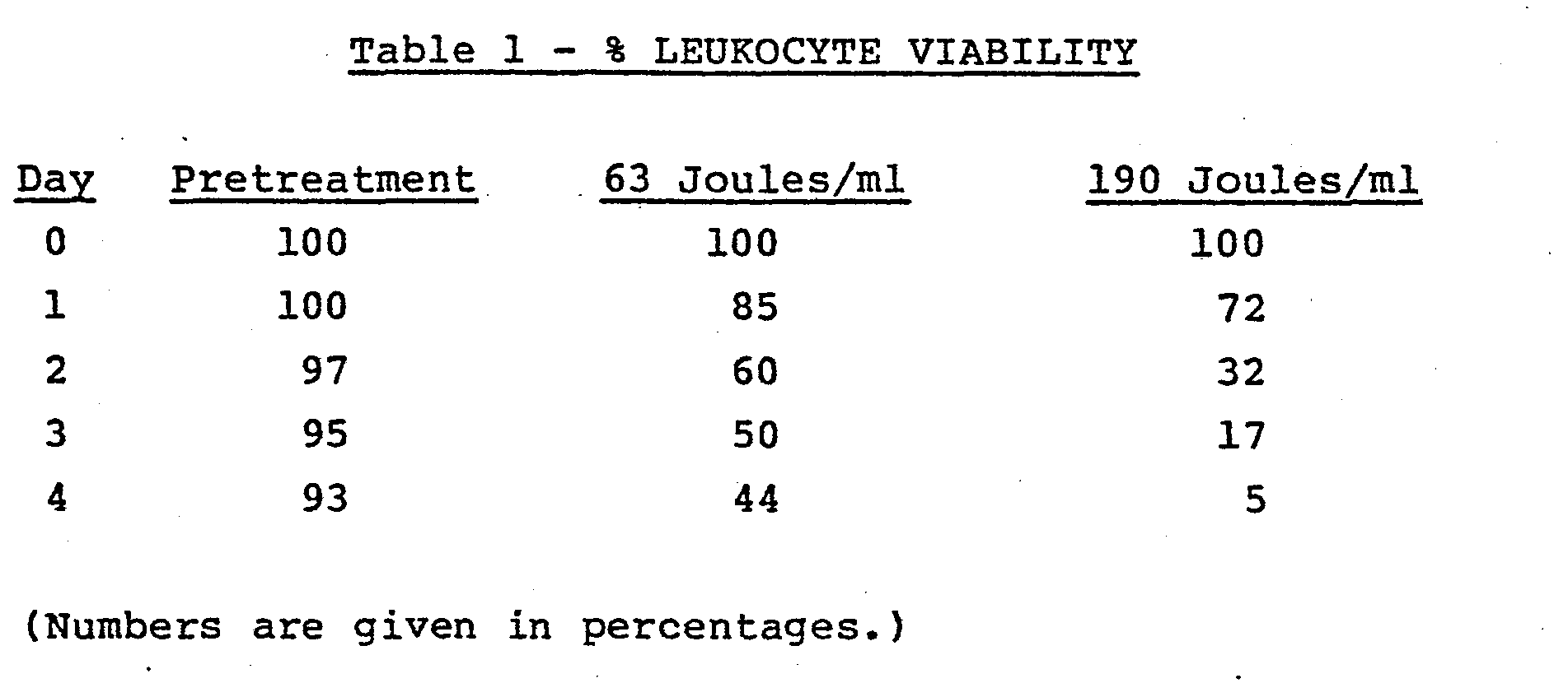
blood treatment center 30 which employs the cassette of'Figure 4 in slidingdrawer 37. The flow of heparin or other clot preventing solution throughpump 31 via a tubing set (not shown) and the flow of blood throughpump 32 from centi-fuge 33 is controlled byclamps 36A, B and C in turn con- ' trolled bycontrol panel 39. Thecentrifuge 33 is a continuous flow type whereby the operator, by viewing through port 34, determines when a leukocyte rich portion of whole blood is obtained. All solutions are collected in bags (not shown) which hang besideinternal access panels 38. After treatment, treated and nontreated blood portions are hung ondrip stand 35 and reinfused into the patient. - A device as that depicted in FIG. 3, having ends sealed with a combination O ring and epoxy material was employed with a Sylvania F8T5/BLB Lamp. A simple recirculating system was constructed comprising a flexible bag for holding the blood and communicating with inlet located at the bottom of the vertically arranged device. The blood was permitted to flow around the lamp, up through the chamber out the exit orifice whereupon it was returned to the bag. Connections were by means of a flexible tube (Tygon tubing) which was run through a roller bearing type pump. Circuit volume was 150 ml of diluted fresh human blood containing 62 ng/ml of 8-methoxy psoralen. The erythrocyte concentration was 6.7 x 10⁸ per ml and the leukocyte concentration was 1.4 x 10⁶ per ml. The priming volume of the device was 25 ml with a blood film thickness of 0.070 inches i.e., the distance between the bulb and the inner surface of the surrounding jacket or tube was 0.07 inches. Blood flow rate was maintained at 50 ml per minute. A pretreatment sample was taken prior to any U.V. exposure and then one sample was run through a circuit such as that described having one device therein and the sample irradiated with 63 joules per ml. An identical system was set up except that 3 tubes in series were employed; flow through each tube being from bottom to top such that 190 joules per ml of irradiation was delivered. The leukocytes were observed for viability over a 4 day period. Viability was determined by treatment with trypsan blue dye and microscopic examination in a manner well-known by those skilled. The results obtained are presented below in Table 1.
- Three devices similar to that shown in FIG. 1 were arranged vertically and connected in serial fashion. Connections were made from the output to a Fenwall 350 cc transfer pack with the inlet thereof running through a blood pump and into the first device's inlet. The blood pump maintained flow at 50 ml per minute. The radiation source was a Sylvania F8T5/BLB lamp. Surrounding the lamp was an inner, U.V. transparent tube having a 7/8" outer diameter. The outer polycarbonate tubing had a 1" outer diameter. The test circuit was primed for 20 minutes with phosphate buffered saline (PBS) and then drained. The sterilized circuitry containing three devices shown in FIG. 1 was primed with 175 cc of leukophoresced blood from a patient who had orally ingested 8-methoxy psoralen two hours prior to being leukophoresced. The cellular concentrations on this phoresced blood sample were 2.8 x 10⁸ rbc/ml and 3.8 x 10⁶ wbc/ml.
- The blood was permitted to circulate through the system for 20 minutes at 50 ml per minute without the lamps being turned on. A pretreatment sample (To) was taken. The lamps were turned on and the blood circulated for 1 hour and 25 minutes at which time sample T1 was taken. Thereafter, the transfer pack was removed from the circuit the venous and arterial lines were connected together and the blood solution allowed to circulate for another 1
hour 20 minutes at which time sample T2 was obtained. - The effective surface area per cell was calculated to be 163 cm2, the effective length 23.5 cm, the priming volume per
cell 28 ml, the blood film thickness approximately 1.6 millimeters and the average power per cell 5.5 milliwatts per cm2. Sample T1 represented cells irradiated with 94 joules per ml and T2 represented cells irradiated with 190 joules per ml. - Viability of the cells was observed from Day 0 to Day 4. The cells were maintained in vitro by addition of growth medium at a 1:1 proportion of cells to growth medium. Growth medium contained
fetal calf serum 30% and 70% RPMI, a well-known tissue culture media. - Results obtained are presented in Table 2 below.

Claims (12)
means for sealing the ends of said second tube with the outer surface of said first tube thereby forming a second chamber between the outer surface of said first tube and the inner surface of said second tube, said second tube further having inlet and outlet means communicating with said second chamber whereby, air may be caused to pass through either chamber of the device so formed, and fluid may be caused to pass through the other chamber.
Applications Claiming Priority (4)
| Application Number | Priority Date | Filing Date | Title |
|---|---|---|---|
| US53723183A | 1983-09-29 | 1983-09-29 | |
| US537231 | 1983-09-29 | ||
| US65060284A | 1984-09-17 | 1984-09-17 | |
| US650602 | 1984-09-17 |
Publications (2)
| Publication Number | Publication Date |
|---|---|
| EP0138489A1 true EP0138489A1 (en) | 1985-04-24 |
| EP0138489B1 EP0138489B1 (en) | 1987-12-23 |
Family
ID=27065421
Family Applications (1)
| Application Number | Title | Priority Date | Filing Date |
|---|---|---|---|
| EP84306667A Expired EP0138489B1 (en) | 1983-09-29 | 1984-09-28 | Apparatus and methods for treating cells with radiation |
Country Status (5)
| Country | Link |
|---|---|
| EP (1) | EP0138489B1 (en) |
| JP (1) | JPS60142862A (en) |
| AU (1) | AU566710B2 (en) |
| CA (1) | CA1253115A (en) |
| DE (1) | DE3468172D1 (en) |
Cited By (16)
| Publication number | Priority date | Publication date | Assignee | Title |
|---|---|---|---|---|
| WO1987000053A1 (en) * | 1985-07-05 | 1987-01-15 | Slichter Sherrill J | Method of reducing immunogenicity and inducing immunologic tolerance |
| EP0240149A1 (en) * | 1986-02-27 | 1987-10-07 | McNeilab, Inc. | Light array assembly for photoactivation patient treatment system |
| EP0241123A1 (en) | 1986-02-27 | 1987-10-14 | McNeilab, Inc. | Improved valve apparatus for photoactivation patient treatment system |
| GB2200020A (en) * | 1986-12-17 | 1988-07-20 | Andrew Gunn | Body fluid processing device |
| WO1989004193A1 (en) * | 1987-11-06 | 1989-05-18 | Francis William Arnold | Device for use in the treatment of lymphocytes |
| US5133932A (en) * | 1988-03-29 | 1992-07-28 | Iatros Limited | Blood processing apparatus |
| US5290221A (en) * | 1990-12-20 | 1994-03-01 | Baxter International Inc. | Systems for eradicating contaminants using photoactive materials in fluids like blood |
| US5300019A (en) * | 1990-12-20 | 1994-04-05 | Baxter International Inc. | Systems and methods for eradicating contaminants using photoactive materials in fluids like blood |
| US5433738A (en) * | 1989-07-12 | 1995-07-18 | Stinson; Randy L. | Method for irradiating cells |
| US5536238A (en) * | 1990-12-20 | 1996-07-16 | Baxter International Inc. | Systems and methods for simultaneously removing free and entrained contaminants in fluids like blood using photoactive therapy and cellular separation techniques |
| US5868695A (en) * | 1990-12-20 | 1999-02-09 | Baxter International Inc. | Systems and methods for eradicating contaminants using photoactive materials in fluids like blood using discrete sources of radiation |
| WO1999050394A1 (en) * | 1998-03-30 | 1999-10-07 | I.D.M. Immuno-Designed Molecules | Suppressive monocyte derived cells, process for their preparation and their uses in pharmaceutical compositions |
| NL1015999C2 (en) * | 2000-08-23 | 2002-02-26 | A J Van Liebergen Holding B V | Device for heating blood or other physiological fluids. |
| SG89337A1 (en) * | 1999-07-09 | 2002-06-18 | Therakos Inc | Method and system for determining an effective amount of light energy to deliver to fluids having targets for the light energy |
| US6800432B1 (en) | 1994-12-06 | 2004-10-05 | Baxter International Inc. | Apparatus and method for inactivating viral contaminants in body fluids |
| DE102010044805A1 (en) * | 2010-09-09 | 2012-03-15 | Heraeus Noblelight Gmbh | Reactor, useful for disinfection or treatment of liquid by ultra violet-C radiation, comprises reactor chamber having chamber wall, which is provided with liquid inlet and outlet, and ultra violet lamp emitting ultra violet-C radiation |
Families Citing this family (2)
| Publication number | Priority date | Publication date | Assignee | Title |
|---|---|---|---|---|
| JPS62284656A (en) * | 1986-06-03 | 1987-12-10 | 株式会社イーゼル | Blood sterilizing method |
| US5150705A (en) * | 1989-07-12 | 1992-09-29 | Stinson Randy L | Apparatus and method for irradiating cells |
Citations (4)
| Publication number | Priority date | Publication date | Assignee | Title |
|---|---|---|---|---|
| US2074909A (en) * | 1936-11-16 | 1937-03-23 | Maximilian L Herzig | Activation device for the heliopyretic treatment of matter |
| GB1266242A (en) * | 1968-10-09 | 1972-03-08 | ||
| FR2426473A1 (en) * | 1978-05-26 | 1979-12-21 | Carraz Gilbert | Treatment of leukaemia by UV irradiation of blood - in presence of a phenothiazine amine as radiation sensitiser |
| US4321919A (en) * | 1979-12-11 | 1982-03-30 | Leukocyte Research, Inc. | Method and system for externally treating human blood |
-
1984
- 1984-09-27 CA CA000464189A patent/CA1253115A/en not_active Expired
- 1984-09-28 JP JP59202133A patent/JPS60142862A/en active Granted
- 1984-09-28 DE DE8484306667T patent/DE3468172D1/en not_active Expired
- 1984-09-28 AU AU33714/84A patent/AU566710B2/en not_active Expired
- 1984-09-28 EP EP84306667A patent/EP0138489B1/en not_active Expired
Patent Citations (4)
| Publication number | Priority date | Publication date | Assignee | Title |
|---|---|---|---|---|
| US2074909A (en) * | 1936-11-16 | 1937-03-23 | Maximilian L Herzig | Activation device for the heliopyretic treatment of matter |
| GB1266242A (en) * | 1968-10-09 | 1972-03-08 | ||
| FR2426473A1 (en) * | 1978-05-26 | 1979-12-21 | Carraz Gilbert | Treatment of leukaemia by UV irradiation of blood - in presence of a phenothiazine amine as radiation sensitiser |
| US4321919A (en) * | 1979-12-11 | 1982-03-30 | Leukocyte Research, Inc. | Method and system for externally treating human blood |
Cited By (22)
| Publication number | Priority date | Publication date | Assignee | Title |
|---|---|---|---|---|
| WO1987000053A1 (en) * | 1985-07-05 | 1987-01-15 | Slichter Sherrill J | Method of reducing immunogenicity and inducing immunologic tolerance |
| EP0240149A1 (en) * | 1986-02-27 | 1987-10-07 | McNeilab, Inc. | Light array assembly for photoactivation patient treatment system |
| EP0241123A1 (en) | 1986-02-27 | 1987-10-14 | McNeilab, Inc. | Improved valve apparatus for photoactivation patient treatment system |
| AU599357B2 (en) * | 1986-02-27 | 1990-07-19 | Mcneilab, Inc. | Light array assembly for photoactivation patient treatment system |
| GB2200020A (en) * | 1986-12-17 | 1988-07-20 | Andrew Gunn | Body fluid processing device |
| GB2200020B (en) * | 1986-12-17 | 1991-06-26 | Andrew Gunn | Body fluid processing device |
| WO1989004193A1 (en) * | 1987-11-06 | 1989-05-18 | Francis William Arnold | Device for use in the treatment of lymphocytes |
| US5133932A (en) * | 1988-03-29 | 1992-07-28 | Iatros Limited | Blood processing apparatus |
| US5433738A (en) * | 1989-07-12 | 1995-07-18 | Stinson; Randy L. | Method for irradiating cells |
| US5300019A (en) * | 1990-12-20 | 1994-04-05 | Baxter International Inc. | Systems and methods for eradicating contaminants using photoactive materials in fluids like blood |
| US5290221A (en) * | 1990-12-20 | 1994-03-01 | Baxter International Inc. | Systems for eradicating contaminants using photoactive materials in fluids like blood |
| US5536238A (en) * | 1990-12-20 | 1996-07-16 | Baxter International Inc. | Systems and methods for simultaneously removing free and entrained contaminants in fluids like blood using photoactive therapy and cellular separation techniques |
| US5868695A (en) * | 1990-12-20 | 1999-02-09 | Baxter International Inc. | Systems and methods for eradicating contaminants using photoactive materials in fluids like blood using discrete sources of radiation |
| US6800432B1 (en) | 1994-12-06 | 2004-10-05 | Baxter International Inc. | Apparatus and method for inactivating viral contaminants in body fluids |
| US6596275B1 (en) | 1998-03-30 | 2003-07-22 | I.D.M. Immuno-Designed Molecules | Monocyte derived cells with immunosuppressive properties, process for their preparation and their uses in pharmaceutical compositions |
| WO1999050394A1 (en) * | 1998-03-30 | 1999-10-07 | I.D.M. Immuno-Designed Molecules | Suppressive monocyte derived cells, process for their preparation and their uses in pharmaceutical compositions |
| SG89337A1 (en) * | 1999-07-09 | 2002-06-18 | Therakos Inc | Method and system for determining an effective amount of light energy to deliver to fluids having targets for the light energy |
| NL1015999C2 (en) * | 2000-08-23 | 2002-02-26 | A J Van Liebergen Holding B V | Device for heating blood or other physiological fluids. |
| WO2002015967A1 (en) * | 2000-08-23 | 2002-02-28 | A.J. Van Liebergen Holding B.V. | Apparatus for heating blood or another physiological fluid |
| CN100364623C (en) * | 2000-08-23 | 2008-01-30 | A·J·万利伯根控股有限公司 | Apparatus for heating blood or another physiological fluid |
| DE102010044805A1 (en) * | 2010-09-09 | 2012-03-15 | Heraeus Noblelight Gmbh | Reactor, useful for disinfection or treatment of liquid by ultra violet-C radiation, comprises reactor chamber having chamber wall, which is provided with liquid inlet and outlet, and ultra violet lamp emitting ultra violet-C radiation |
| DE102010044805B4 (en) * | 2010-09-09 | 2017-03-23 | Heraeus Noblelight Gmbh | Reactor for degerming or treatment of a liquid by means of UVC radiation |
Also Published As
| Publication number | Publication date |
|---|---|
| EP0138489B1 (en) | 1987-12-23 |
| JPH0547222B2 (en) | 1993-07-16 |
| DE3468172D1 (en) | 1988-02-04 |
| JPS60142862A (en) | 1985-07-29 |
| AU3371484A (en) | 1985-04-18 |
| CA1253115A (en) | 1989-04-25 |
| AU566710B2 (en) | 1987-10-29 |
Similar Documents
| Publication | Publication Date | Title |
|---|---|---|
| EP0138489B1 (en) | Apparatus and methods for treating cells with radiation | |
| JP2596929B2 (en) | Light source array assembly for light activated patient treatment systems | |
| US4573960A (en) | Three phase irradiation treatment process | |
| US4578056A (en) | Patient photopheresis treatment apparatus and method | |
| US4921473A (en) | Multicomponent fluid separation and irradiation system | |
| CA1253742A (en) | Pump block for interfacing irradiation chamber to photoactivation patient treatment system | |
| ES2265869T3 (en) | SYSTEM TO DETERMINE AN EFFECTIVE AMOUNT OF ENERGY TO SUPPLY IT TO FLUIDS IN PHOTOTHERAPY. | |
| US4737140A (en) | Irradiation chamber for photoactivation patient treatment system | |
| US4568328A (en) | Automated photophoresis blood portion control methods and apparatus | |
| US5628727A (en) | Extracorporeal virioncidal apparatus | |
| JP2005511209A (en) | Manual processing system and method for providing blood components tailored for pathogen inactivation | |
| US4681568A (en) | Valve apparatus for photoactivation patient treatment system | |
| JP2016083370A (en) | Methods and systems for collecting mononuclear cells | |
| EP0239255A1 (en) | Demountable peristaltic pump for photoactivation patient treatment system | |
| CA1263578A (en) | Zero insertion force socket for photoactivation patient treatment system | |
| WO2020238150A1 (en) | In-vivo closed-loop sterilization apparatus | |
| US11672898B2 (en) | Microfluidic removal of excess bilirubin from blood | |
| EP0240152B1 (en) | Irradiation chamber for photoactivation patient treatment system | |
| PL227190B1 (en) | Device for photobiomodulation of blood during the extracorporal circulation | |
| EP0239256A1 (en) | Concurrent on-line irradiation treatment system | |
| Girard | Future Directions in Transfusion Practice | |
| UA5464U (en) | Device for extracorporeal ultraviolet irradiation of transfusion solutions |
Legal Events
| Date | Code | Title | Description |
|---|---|---|---|
| PUAI | Public reference made under article 153(3) epc to a published international application that has entered the european phase |
Free format text: ORIGINAL CODE: 0009012 |
|
| AK | Designated contracting states |
Designated state(s): BE DE FR GB IT |
|
| 17P | Request for examination filed |
Effective date: 19850927 |
|
| RAP1 | Party data changed (applicant data changed or rights of an application transferred) |
Owner name: MCNEILAB, INC. |
|
| 17Q | First examination report despatched |
Effective date: 19861015 |
|
| GRAA | (expected) grant |
Free format text: ORIGINAL CODE: 0009210 |
|
| AK | Designated contracting states |
Kind code of ref document: B1 Designated state(s): BE DE FR GB IT |
|
| REF | Corresponds to: |
Ref document number: 3468172 Country of ref document: DE Date of ref document: 19880204 |
|
| ET | Fr: translation filed | ||
| ITF | It: translation for a ep patent filed |
Owner name: SOCIETA' ITALIANA BREVETTI S.P.A. |
|
| PLBE | No opposition filed within time limit |
Free format text: ORIGINAL CODE: 0009261 |
|
| STAA | Information on the status of an ep patent application or granted ep patent |
Free format text: STATUS: NO OPPOSITION FILED WITHIN TIME LIMIT |
|
| 26N | No opposition filed | ||
| ITTA | It: last paid annual fee | ||
| PGFP | Annual fee paid to national office [announced via postgrant information from national office to epo] |
Ref country code: FR Payment date: 20010911 Year of fee payment: 18 |
|
| PGFP | Annual fee paid to national office [announced via postgrant information from national office to epo] |
Ref country code: GB Payment date: 20010926 Year of fee payment: 18 |
|
| PGFP | Annual fee paid to national office [announced via postgrant information from national office to epo] |
Ref country code: DE Payment date: 20011015 Year of fee payment: 18 |
|
| PGFP | Annual fee paid to national office [announced via postgrant information from national office to epo] |
Ref country code: BE Payment date: 20011116 Year of fee payment: 18 |
|
| REG | Reference to a national code |
Ref country code: GB Ref legal event code: IF02 |
|
| PG25 | Lapsed in a contracting state [announced via postgrant information from national office to epo] |
Ref country code: GB Free format text: LAPSE BECAUSE OF NON-PAYMENT OF DUE FEES Effective date: 20020928 |
|
| PG25 | Lapsed in a contracting state [announced via postgrant information from national office to epo] |
Ref country code: BE Free format text: LAPSE BECAUSE OF NON-PAYMENT OF DUE FEES Effective date: 20020930 |
|
| BERE | Be: lapsed |
Owner name: *MCNEILAB INC. Effective date: 20020930 |
|
| PG25 | Lapsed in a contracting state [announced via postgrant information from national office to epo] |
Ref country code: DE Free format text: LAPSE BECAUSE OF NON-PAYMENT OF DUE FEES Effective date: 20030401 |
|
| GBPC | Gb: european patent ceased through non-payment of renewal fee |
Effective date: 20020928 |
|
| PG25 | Lapsed in a contracting state [announced via postgrant information from national office to epo] |
Ref country code: FR Free format text: LAPSE BECAUSE OF NON-PAYMENT OF DUE FEES Effective date: 20030603 |
|
| REG | Reference to a national code |
Ref country code: FR Ref legal event code: ST |