EP0338896A1 - Method and apparatus for treating tap water by electrical modulated duration pulses - Google Patents
Method and apparatus for treating tap water by electrical modulated duration pulses Download PDFInfo
- Publication number
- EP0338896A1 EP0338896A1 EP89401021A EP89401021A EP0338896A1 EP 0338896 A1 EP0338896 A1 EP 0338896A1 EP 89401021 A EP89401021 A EP 89401021A EP 89401021 A EP89401021 A EP 89401021A EP 0338896 A1 EP0338896 A1 EP 0338896A1
- Authority
- EP
- European Patent Office
- Prior art keywords
- water
- treatment
- pulses
- duration
- temperature
- Prior art date
- Legal status (The legal status is an assumption and is not a legal conclusion. Google has not performed a legal analysis and makes no representation as to the accuracy of the status listed.)
- Granted
Links
Images


Classifications
-
- C—CHEMISTRY; METALLURGY
- C02—TREATMENT OF WATER, WASTE WATER, SEWAGE, OR SLUDGE
- C02F—TREATMENT OF WATER, WASTE WATER, SEWAGE, OR SLUDGE
- C02F1/00—Treatment of water, waste water, or sewage
- C02F1/46—Treatment of water, waste water, or sewage by electrochemical methods
- C02F1/4602—Treatment of water, waste water, or sewage by electrochemical methods for prevention or elimination of deposits
-
- C—CHEMISTRY; METALLURGY
- C02—TREATMENT OF WATER, WASTE WATER, SEWAGE, OR SLUDGE
- C02F—TREATMENT OF WATER, WASTE WATER, SEWAGE, OR SLUDGE
- C02F1/00—Treatment of water, waste water, or sewage
- C02F1/46—Treatment of water, waste water, or sewage by electrochemical methods
- C02F1/461—Treatment of water, waste water, or sewage by electrochemical methods by electrolysis
- C02F1/463—Treatment of water, waste water, or sewage by electrochemical methods by electrolysis by electrocoagulation
-
- C—CHEMISTRY; METALLURGY
- C02—TREATMENT OF WATER, WASTE WATER, SEWAGE, OR SLUDGE
- C02F—TREATMENT OF WATER, WASTE WATER, SEWAGE, OR SLUDGE
- C02F1/00—Treatment of water, waste water, or sewage
- C02F1/46—Treatment of water, waste water, or sewage by electrochemical methods
- C02F1/461—Treatment of water, waste water, or sewage by electrochemical methods by electrolysis
- C02F1/46104—Devices therefor; Their operating or servicing
- C02F1/46109—Electrodes
- C02F2001/46152—Electrodes characterised by the shape or form
-
- C—CHEMISTRY; METALLURGY
- C02—TREATMENT OF WATER, WASTE WATER, SEWAGE, OR SLUDGE
- C02F—TREATMENT OF WATER, WASTE WATER, SEWAGE, OR SLUDGE
- C02F2201/00—Apparatus for treatment of water, waste water or sewage
- C02F2201/46—Apparatus for electrochemical processes
- C02F2201/461—Electrolysis apparatus
- C02F2201/46105—Details relating to the electrolytic devices
- C02F2201/4616—Power supply
- C02F2201/4617—DC only
-
- C—CHEMISTRY; METALLURGY
- C02—TREATMENT OF WATER, WASTE WATER, SEWAGE, OR SLUDGE
- C02F—TREATMENT OF WATER, WASTE WATER, SEWAGE, OR SLUDGE
- C02F2201/00—Apparatus for treatment of water, waste water or sewage
- C02F2201/46—Apparatus for electrochemical processes
- C02F2201/461—Electrolysis apparatus
- C02F2201/46105—Details relating to the electrolytic devices
- C02F2201/4616—Power supply
- C02F2201/46175—Electrical pulses
-
- C—CHEMISTRY; METALLURGY
- C02—TREATMENT OF WATER, WASTE WATER, SEWAGE, OR SLUDGE
- C02F—TREATMENT OF WATER, WASTE WATER, SEWAGE, OR SLUDGE
- C02F2209/00—Controlling or monitoring parameters in water treatment
- C02F2209/02—Temperature
-
- C—CHEMISTRY; METALLURGY
- C02—TREATMENT OF WATER, WASTE WATER, SEWAGE, OR SLUDGE
- C02F—TREATMENT OF WATER, WASTE WATER, SEWAGE, OR SLUDGE
- C02F2209/00—Controlling or monitoring parameters in water treatment
- C02F2209/05—Conductivity or salinity
-
- C—CHEMISTRY; METALLURGY
- C02—TREATMENT OF WATER, WASTE WATER, SEWAGE, OR SLUDGE
- C02F—TREATMENT OF WATER, WASTE WATER, SEWAGE, OR SLUDGE
- C02F2301/00—General aspects of water treatment
- C02F2301/02—Fluid flow conditions
- C02F2301/022—Laminar
-
- C—CHEMISTRY; METALLURGY
- C02—TREATMENT OF WATER, WASTE WATER, SEWAGE, OR SLUDGE
- C02F—TREATMENT OF WATER, WASTE WATER, SEWAGE, OR SLUDGE
- C02F2303/00—Specific treatment goals
- C02F2303/22—Eliminating or preventing deposits, scale removal, scale prevention
Definitions
- the present invention relates to a method and a device for treating water in the distribution network by electric pulses of modulated duration, in order to avoid or greatly reduce the phenomenon of scaling of the pipes of a network.
- the present invention aims to remedy the aforementioned drawbacks, by implementing a method and a treatment device of the aforementioned type in which the duration of the electrical pulses applied to the water of the distribution network is modulated by duration as a function of temperature.
- Another object of the present invention is the implementation of a method and a device for treating water by electrical pulses allowing an optimized treatment according to the physical parameters of the water such as the electrical conductivity of the latter.
- the process for the physical treatment of the water in the distribution network which is the subject of the invention consists in applying to the water in the distribution network a series of electrical pulses known as recurrence frequency treatment pulses proportional to the flow of water. of the distribution network. It is remarkable in that the duration of the pulses is modulated as a function of the temperature of the water so as to cause, during the duration of maintenance of each treatment pulse, microscopic flocculation of the calcium carbonate contained in the water and the diffusion of microscopic flakes of calcium carbonate outside the duration of maintenance of the impulse.
- the device for treating the water in the distribution network by electric pulses of modulated duration which is the subject of the invention comprises a water treatment chamber in which the water from the distribution network is circulating, means for measuring the water flow and electrical pulse generating means applied to the treatment chamber and the frequency of recurrence of which is proportional to the measured water flow. It is remarkable in that it further comprises means for measuring the temperature of the water and means for modulating the duration of the pulses as a function of the temperature of the water, so as to cause, during the duration maintenance of each pulse, a microscopic flocculation of calcium carbonate contained in the water and the diffusion of microscopic flakes of calcium carbonate outside the duration of maintenance of the pulse.
- the method and the device of the invention find application in the treatment of water from the distribution network at the subscriber with a view to greatly or practically reducing the risks of scaling of subscriber installations, such as heat exchangers, heating circuits, hot water production circuits.
- FIGS. 1 and 2a and 2b The process for treating the water in the distribution network by electric pulses of modulated duration in accordance with the object of the present invention will be described with FIGS. 1 and 2a and 2b.
- the solubility of calcium carbonate is governed by the law of mass action, which defines an equilibrium constant whose value depends on the temperature and the degree of ionization of the water.
- the water is not saturated and is said to be aggressive because it can dissolve solid calcium carbonate. If this product is greater than this constant, water is on the contrary capable of generating a deposit of calcium carbonate and is said to be calcifying.
- a calcocarbon equilibrium curve makes it possible to define the conditions of equilibrium between water and solid calcium carbonate, but does not make it possible to predict the conditions of appearance of the latter on the surface of a material other than carbonate calcium.
- the appearance of a particle of calcium carbonate, designated by germ, on the surface of a metal wall requires that the product of the concentrations of calcium ions and bicarbonate is approximately forty times greater than the equilibrium constant.
- the method of physical treatment of the water in the distribution network consists in applying to the water of the distribution network a series of electrical pulses of constant amplitude and frequency of recurrence directly proportional to the flow of water from the distribution network.
- the amplitude of the pulses is chosen so as to apply to the water to be treated a difference in electrical ptotential of 50 volts per centimeter of water thickness, the pulses having an amplitude of 300 Volts.
- the duration of the pulses is modulated as a function of the temperature of the water, so as to cause, during the duration of maintenance of each pulse, microscopic flocculation of the calcium carbonate contained in the water. and the diffusion therein of microscopic flakes of calcium carbonate outside the duration of the pulse maintenance.
- the application of a potential difference or electric field between two electrodes has the effect of creating: - a cathode in the vicinity of which reduction reactions take place and in particular those of dissolved oxygen WHERE + 2H2O + 4 e ⁇ 40 H - an anode, in the vicinity of which oxidation reactions occur 2H2O ⁇ WHERE + 4 H + 4 e O ions H products in the vicinity of the cathode cause a shift in carbon equilibria, which produces a local increase in the concentration of carbonate ions CO3 ⁇ , the water can become strongly calcifying. Solid calcium carbonate germs can then appear.
- the application of pulses of modulated duration thus allows the production of calcium carbonate germs during the duration of the pulse and the flocculation in microscopic flakes.
- the microscopic flakes or germs diffuse in the water outside the duration of maintenance of the impulse.
- the existence in water, under the effect of the treatment of microscopic germs or flakes of calcium carbonate disrupts the formation of new germs from the wall of the pipes because the energy of precipitation or flocculation on a germ or flake microscopic existing in water is weaker than the energy of formation of a germ on the wall of the pipes from where the inhibiting effect of the scaling phenomenon.
- the duration of each pulse is inversely proportional to the temperature of the water as shown in FIG. 2a.
- the abscissa axis is graduated in ° C and the ordinate axis in microseconds.
- the duration of the pulses is between 5 ° and 60 °.
- the duration of each treatment pulse is modulated as a function of the electrical conductivity of the water in order to allow microscopic flocculation of the calcium carbonate under substantially stable electric field conditions. applied to water.
- substantially stable conditions of the electric field applied to water is meant in particular the absence of dielectric breakdown and taken into account via the aforementioned electrical conductivity of the water of the ionization thereof and in particular of the concentration of carbonate ions for example.
- the duration of each processing pulse is thus modulated according to a continuously decreasing law as a function of the electrical conductivity of the 'water, electrical conductivity ⁇ .
- the duration of each treatment pulse is thus between one and 8 microseconds for an electrical conductivity of the water between 5,000 ⁇ S and 2,500 ⁇ S, the duration T1 of the treatment pulses being modulated as a function of this conductivity as shown in Figure 2b.
- each treatment pulse, negative pulse is followed by an opposite polarity pulse, positive pulse, so as to promote the detachment of microscopic carbonate germs or flakes. calcium likely to form on the wall of the electrode playing the role of cathode on which the negative treatment pulses are applied.
- the negative pulses have an amplitude of approximately 300 Volts and the positive pulses of opposite polarity have an amplitude limited to 50 Volts for example.
- the device for treating the water in the distribution network by electrical pulses in accordance with the subject of the invention comprises a chamber 1 for treating the water in which the water in the distribution network is in circulation.
- Means 2 for measuring the water flow and means 3 generators electrical pulses, designated by the processing pulses, are provided, the electrical processing pulses being applied to the processing chamber 1.
- the frequency of recurrence of the processing pulses, ie ultimately the period ⁇ of recurrence of these pulses, is proportional to the measured water flow.
- the device which is the subject of the invention comprises, in a particularly advantageous manner for implementing the method described above, means 4 for measuring the temperature of the water, these means delivering a signal representative of this temperature.
- Means 5 for modulating the duration of the treatment pulses as a function of the temperature are provided so as to cause, during the maintenance period of each treatment pulse, duration denoted T1, a microscopic flocculation of the calcium carbonate contained in the water and the diffusion of the microscopic flakes of calcium carbonate thus formed outside the duration of maintenance of the treatment pulse.
- the aforementioned microscopic flakes are diffused in the water distributed by the network, these flakes remaining in suspension therein.
- the device which is the subject of the invention comprises means 6 for measuring the electrical conductivity of the water and means denoted 50 for modulating the duration of the treatment pulses as a function of the electrical conductivity of the water so to cause, during the holding time of each treatment pulse, the aforementioned microscopic flocculation of calcium carbonate under substantially stable conditions of electric field applied to water, and in particular in the absence of dielectric breakdown.
- Modulating the duration of treatment pulses T1 as a function of the electrical conductivity of the treated water makes it possible to take into account the degree of ionization of the water and the duration of each pulse of treatment, or holding time T1, is thus modulated according to a continuously decreasing law as a function of the electrical conductivity of the water, conductivity noted ⁇ .
- the duration of each treatment pulse is between 1 microsecond and 8 microseconds for an electrical conductivity of the water between 5,000 ⁇ S and 2,500 ⁇ S.
- the resistors denoted r and the capacitors denoted c denote resistors and capacitors necessary for the implementation of electronic components normally available on the market, these resistors and these capacitors playing no particular functional role. if not that of the implementation and in particular of the suitable polarization of the aforementioned electronic circuits or components.
- the means 2 for measuring the water flow rate include, without limitation, a turbine Tu arranged in the treatment chamber 1 as will be described in more detail later in the description . They also include a speed sensor 20 coupled to the turbine Tu, this speed sensor delivering a periodic signal whose frequency is proportional to the water flow.
- the speed sensor 20 can be constituted by a Hall effect detector marketed in France by the company SPRAGUE under the reference UGN 3501T for example.
- the speed sensor delivers a periodic signal whose frequency is proportional to the water flow rate, this signal being delivered to an amplification stage 21.
- the amplification stage 21 is constituted by amplifier elements with transistors or with operational amplifiers as shown in FIG. 4 but will not be described in detail since the production of this amplifier is within the reach of those skilled in the art.
- the means 2 for measuring the water flow rate further comprise frequency / voltage conversion means 22 making it possible to deliver a proportional DC voltage to the water flow rate.
- the frequency / voltage conversion means 22 can advantageously be constituted by a converter circuit sold under the reference 2917 N8 by the company NATIONAL SEMICONDUCTORS.
- the frequency / voltage conversion means 22 receive the amplified signal delivered by the amplifier stage 21.
- the means 2 for measuring the water flow comprise, as shown in FIG. 4, frequency-controlled oscillator means denoted 23, the frequency-controlled oscillator means receiving the DC voltage proportional to the water flow and delivering a signal of control whose frequency of recurrence is proportional to the water flow.
- the frequency-controlled oscillator means 23 may as shown in FIG. 4 be constituted by an integrated circuit sold under the reference 566 by the company NATIONAL SEMICONDUCTORS.
- This frequency-controlled oscillator circuit denoted 230 is a divider circuit 231 which ultimately makes it possible to deliver the control signal whose recurrence frequency is proportional to the water flow.
- the divider circuit 231 can be produced by a circuit sold under the reference 4017 by the company NATIONAL SEMICONDUCTORS.
- the modulation means 5 are constituted by a circuit 50 variator of duty cycle of the control pulses, the control pulses being of course synchronous with the processing pulses as will be explained later in the description. So the duty cycle of the processing pulses is defined by the ratio T1 ⁇ and the report cyclic control pulses is defined in the same way.
- the circuit 50 of duty cycle variator can advantageously be constituted by a circuit marketed under the reference LM555 by the company NATIONAL SEMICONDUCTORS.
- An output terminal of the duty cycle variator circuit 50 is connected to optoelectronic emitting means 51 constituted for example by a photodiode with infrared radiation to ensure the transmission of control pulses of duration modulated as a function of temperature.
- optoelectronic emitting means 51 is not limiting, but this makes it possible to ensure suitable galvanic decoupling with the high voltage part of the device constituted by the treatment pulse generator, which will be described later. in the description.
- the means 4 for measuring the water temperature advantageously comprise a temperature measurement probe 40 placed in the treatment chamber 1, this probe delivering a DC voltage signal representative of the temperature of the water.
- the temperature measurement probe can advantageously consist of a probe sold by the company NATIONAL SEMICONDUCTORS under the reference LM35.
- the means 4 for measuring the temperature also include a frequency controlled oscillator 41, this oscillator receiving on a control input the DC voltage signal representative of the water temperature and delivers a periodic signal whose frequency is proportional to the water temperature.
- the frequency-controlled oscillator 41 can advantageously be constituted by a component sold under the reference LM331 by the company NATIONAL SEMICONDUCTORS.
- the continuous signal delivered by the probe 40 is applied to the input n ° 7 of the aforementioned circuit.
- the temperature measurement means 4 finally comprise a frequency / voltage converter circuit 42 receiving the periodic signal delivered by the frequency-controlled oscillator 41 and delivering on a output terminal a direct voltage constituting the signal representative of the temperature of the water delivered by the temperature measurement means 4.
- the frequency / voltage converter circuit 42 can be constituted by a circuit sold under the reference 2917 N8 by the company NATIONAL SEMICONDUCTORS.
- the output terminal delivering the signal representative of the water temperature is then terminal No. 5.
- the output terminal No. 5 of the circuit constituting the circuit 42 frequency / voltage converter of the temperature measurement means 4 is then connected via an adjustment potentiometer denoted 420 to the polarization input terminal 5 of the circuit. 50 duty cycle dimmer for control pulses.
- the embodiment represented in FIG. 4 of the flow measurement means 2, of the temperature measurement means 4 and of the means 5 for modulating the duration of the treatment pulses as a function of the temperature allows modulation of the duration T1 of the treatment pulses, of course by the corresponding modulation of the duty cycle of the control pulses, as a function of the water temperature.
- the means 3 pulse generators advantageously comprise means 30 generators of a high continuous supply voltage.
- the aforementioned means 30 make it possible to generate a voltage of the order of 300 Volts and can be constituted by any rectified power supply system making it possible to generate a direct voltage with floating potential with respect to ground.
- floating potential with respect to ground is understood a system as shown in FIG. 3 in which the secondary windings of the supply transformer, transformer 300, are not connected to a reference potential such as ground, positive potential, terminal + and negative, terminal - of the rectified voltage delivered by the means 30 generators of high direct voltage not being defined with respect to the mass of the device.
- the amplitude of 300 volts of the DC voltage generated by the means 30 generating high DC voltage is defined between the positive terminal and the negative output terminal of the aforementioned generator means 30.
- a detailed description of the means 30 generating high DC voltage is not necessary since this type of high voltage DC power supply is known to those skilled in the art.
- the means for generating electrical processing pulses comprise switching means 31 constituted by a power C-MOS transistor, these switching means being connected in parallel on a capacitor 32, the source terminal of the MOS switching transistor. of power being connected to one of the terminals of the capacitor and the drain terminal of the switching transistor 31 being connected to the other terminal of the capacitor 32 by means of a protection diode denoted 33.
- the means of switching 31 constituted by the switching MOS transistor comprise a control input terminal constituted by the gate terminal of the MOS transistor.
- the source terminal of the switching MOS transistor 31 is connected to the negative terminal of the means 30 generating high DC supply voltage.
- the means 3 for processing pulses also include a charging circuit for the capacity 32 making it possible to generate the processing pulses.
- the charging circuit includes a transformer 34, the primary winding of which is in series with a connection terminal 340 making it possible to connect the processing chamber 1 and in particular the peripheral electrode thereof, as will be described later in the description, in series in the load circuit of the capacity 32.
- connection in series of the processing chamber as represented in FIG. 5, it will be understood that the equivalent resistance comprised between the peripheral electrode and the central electrode of the treatment chamber, equivalent resistance constituted by the water to be treated, is connected in series between the aforementioned connection terminal 340 and for example another terminal 341, which is connected to the ground reference potential of the device.
- the capacity 32 charging circuit is then closed by means of a resistor 37 whose function will be explained later in the description, this resistor being connected to the ground reference voltage of the device on the one hand and to the positive output terminal of the high supply voltage generator means 30.
- the means 3 for generating electrical pulse processing include optoelectronic receiving means 35, which are of course coupled to the optoelectronic transmitting means 51 of the modulation means 5 of the duration of the control pulses.
- the receiving optoelectronic means 35 comprise for example a receiving phototransistor 350 to which is connected on the collector electrode thereof a series of inverters 351 in order to obtain a low impedence output from phototransistor 350.
- the low impedence output of all circuits 351 is connected to the gate terminal constituting terminal control input of the switching means constituted by the switching C-MOS transistor 31.
- the supply transformer 300 comprises an auxiliary winding 301, which makes it possible to generate a direct supply voltage denoted VCC, which makes it possible to supply in particular the phototransistor 350.
- the frequency of recurrence of the control pulses, and ultimately the frequency of recurrence of the treatment pulses is controlled by the measurement of the flow rate carried out by the turbine Tu and by the chain constituting the means 2 for measuring the flow rate.
- the frequency of recurrence of the control pulses and of the treatment pulses is fixed and the control pulses transmitted by the pulse duration modulating means constituting a cyclic ratio variator of the control pulses then allows starting from the information transmitted by the temperature measurement means 4, to modulate accordingly the duration of maintenance T1 of the processing pulses by means of the command of the duty cycle of the command pulses.
- the control pulses are transformed into light pulses by the light-emitting diode 51 and these light pulses are received by the phototransistor 350 coupled to the aforementioned light-emitting diode.
- the electrical pulses delivered by the phototransistor 350 are then transmitted by the low impedance circuits 351 to the terminal of control of the switching means 31, which then allow the almost instantaneous discharge in a few microseconds of the capacity 32 by switching on the circuit of the switching means or C-MOS transistors 31.
- the short-circuiting of the switching and switching transistors 31 the capacity 32 is maintained during the holding time T1 thus forming the holding time of the processing pulse.
- the switching C-MOS transistor 31 Upon switching of the control pulse, the switching C-MOS transistor 31 is again blocked and the capacitor 32 is recharged with a time constant corresponding substantially to that of this capacitor 32 connected in series with the equivalent resistance of the chamber of treatment 1, the resistance of low value 37 and the resistance of the primary winding of the transformer 34.
- the transformer 34 is used in order to obtain information on the secondary windings of the latter, relating to the intensity of the electric current passing through the treatment chamber 1 in order to display the state parameters of the device during the water treatment as will be described later in the description.
- the means 3 for processing pulses furthermore include in parallel on the load circuit a self-inductance 36 constituting with the capacitor 32 a damped resonant circuit.
- This damped resonant circuit makes it possible to generate, following the charging of the capacitor 32, the pulse of polarity opposite to the discharging pulse of the capacitor forming the processing pulse.
- the damped resonant circuit thus formed has the effect of generating a damped oscillation, the first maximum of which is superimposed on the charge curve of the capacitor 32, thus constituting the peak of polarity opposite to the treatment pulse.
- the means 6 for measuring the electrical conductivity of the water consist of the resistor 37 of low value represented in FIG. 5. This resistor makes it possible to generate a voltage signal proportional to the electric current flowing in the treatment chamber 1.
- the means 6 for measuring the electrical conductivity of the water comprise a rectifier circuit denoted 60, 61 constituted by diodes, this rectifier circuit being connected to the terminals of the resistor 37 and allowing d '' generate a DC voltage proportional to the electric current flowing in the treatment chamber.
- the rectifier circuit 60, 61 is connected to a polarization control input of the frequency converter / voltage converter circuit 42 of the water temperature measurement means 4.
- the operation of the device as shown in FIGS. 4 and 5 is as follows: - during the variation of the electrical conductivity ⁇ of the water, the treatment pulses being of substantially constant amplitude equal to 300 Volts, the current flowing in the charge circuit of the capacity 32 and ultimately in the treatment chamber 1 varies accordingly and produces at the terminals of the low-value resistor 37 a corresponding potential difference representative of this intensity.
- the rectifier circuit 60, 61 then delivers a rectified direct voltage proportional to the electric current flowing in the treatment chamber.
- This voltage has the effect of modifying the polarization of the frequency / voltage converter 42 of the means for measuring the water temperature, which has the effect of modifying the output voltage delivered by the potentiometer 420, voltage intended to modulate the ratio cyclic pulses of control at the duty cycle controller circuit of the control pulses 50.
- Figures 4 and 5 allows for a modulation of the duration T1 of maintaining the processing pulses in accordance with the laws of variations shown in Figures 2a and 2b previously described in the description.
- the device which is the subject of the invention, it comprises, as shown in FIG. 3, means 7, 8 for displaying the operating parameters of the device, parameters such as the flow of water, water temperature, frequency of treatment pulses, switching the device on or off, a device fault alarm for example.
- the aforementioned display means comprise for example a multiplexer 70 receiving the signals representative of the aforementioned parameters in parallel.
- These signals can advantageously be constituted by the frequency signals 12, 13 delivered respectively by the frequency controlled oscillator 230 and by the frequency controlled oscillator 41, these signals being respectively representative of the water flow and the temperature of l 'water.
- the other signals can also consist of corresponding frequency signals but these signals will not be described and the corresponding circuits likely to generate them will not be described either because they correspond to embodiments within the reach of the skilled person.
- the multiplexers 70 deliver coded signals in serial sequence in the form of coded pulses.
- the multiplexer 70 will not be described since it corresponds to a multiplexer of the conventional type, which is perfectly known to those skilled in the art in principle.
- the display means 7, 8 include means 71 for formatting the coded pulses.
- the means for shaping the coded pulses receive the signals delivered by the multiplexer 70, that is to say the coded pulses, and they comprise, connected to a DC voltage supply terminal 2VDC for example via a choke inductor providing filtering with a capacitor 711, a switching transistor of type C-MOSnoted 712, the gate terminal of which is connected to the input terminal of the coded pulses, the drain terminal of which is connected to the choke inductor 710 and whose source terminal is connected to the output terminal of the shaped pulses.
- a Zener diode 71 is connected in parallel between the source terminal and the gate terminal of the switching transistor 712.
- a load resistor 714 is connected between the drain terminal and the source terminal of the switching transistor 712.
- a satellite display member 8 as shown in Figure 1 is provided.
- the satellite display member 8 includes a coded pulse decoder circuit, which will not be described since it corresponds to a known decoder system for decoding coded multiplexed pulses.
- the satellite display member 8 is connected to the shaping means 71 via a coaxial socket for example.
- the satellite display member 8 can advantageously be either plugged directly into the coaxial socket, the satellite display member 8 then being secured to the device and in particular the box thereof or on the contrary be connected to the means shaping 71 via a coaxial cable, the coaxial cable can be a coaxial cable of great length, up to 100 meters.
- the device which is the subject of the invention can be installed in the outbuildings of the home of a domestic subscriber and the satellite display unit can on the contrary be installed in a vestibule or in a suitable place in the living area.
- the treatment chamber 1 comprises a peripheral cylindrical electrode 10 to which the treatment pulses are applied. It also includes a central cylindrical electrode 11 connected to the reference voltage or ground of the device.
- An envelope 12 of electrical insulating material surrounds the peripheral cylindrical electrode 10 and constitutes a sealed enclosure for the water to be treated.
- a first 13 and second 14 end blocks constitute the front walls of the treatment chamber, each end block 13 and 14 being provided with a central pipe 131, 141 for the arrival or departure of water. of the treatment chamber.
- the sealing of the treatment chamber can be ensured between the peripheral electrode 10 and the first and second end blocks 13 and 14 by means of seals 101, 102.
- the envelope of electrically insulating material can advantageously be constituted by an envelope of polyvinyl chloride or PVC.
- the end block 13 comprising the central inlet pipe 131 is provided on this pipe with the turbine Tu for measuring the water flow rate.
- the central cylindrical electrode 11 has one end integral with the second end block 14.
- the central electrode is partially hollow to constitute the starting pipe 141 for the water, this hollow electrode being provided in the vicinity of the second end block of through orifices 110 connecting the treatment chamber 1 and the starting pipe 141.
- the other end 111 of the central electrode 11 is placed in the vicinity of the first block 13 and the Tu turbine.
- the end 111 of the central electrode placed in the vicinity of the turbine Tu has a frustoconical shape in order to ensure a random distribution of the water veins leaving the the turbine.
- random distribution of the water streams leaving the turbine it will be understood that the water streams leaving the turbine meeting the aforementioned frustoconical end are not subjected to any preferential path capable of creating, at the level of the flow of water, an inhomogeneity likely to lead to a different treatment according to the corresponding zones.
- the turbine Tu used is a turbine which is not capable of creating turbulence before the entry of the water from treatment chamber 1.
- the wall of the end 111 of frustoconical shape of the central cylindrical electrode 11 is provided with helical grooves and the end of the central electrode 11 is rotatably mounted free around the longitudinal axis ⁇ of symmetry of the treatment chamber 1 and of the central electrode 11.
- the implementation of the process which is the subject of the invention by means of the device described above has the effect of greatly reducing the problems of scaling of pipes, in particular pipes for the circuit for producing hot water or for heating domestic installations or industrial.
- the method and the device which are the subject of the invention can also be used for the treatment edible water, the process which is the subject of the invention having at most the effect of a slight increase in the turbidity of the water due to the microscopic flocculation of calcium carbonate and of the diffusion thereof in the water of distribution.
Abstract
Description
La présente invention est relative à un procédé et à un dispositif de traitement de l'eau du réseau de distribution par impulsions électriques à durée modulée, afin d'éviter ou réduire fortement le phénomène d'entartrage des canalisations d'un réseau.The present invention relates to a method and a device for treating water in the distribution network by electric pulses of modulated duration, in order to avoid or greatly reduce the phenomenon of scaling of the pipes of a network.
Les traitements physiques des eaux de réseaux de distribution par impulsions électriques a fait l'objet jusqu'à ce jour de nombreux travaux. En particulier, il a été proposé par les demanderesses, en vue d'éviter le phénomène d'entartrage des canalisations, d'effectuer un traitement de l'eau à distribuer par des impulsions électriques à gradation de puissance. Selon un aspect plus particulier du mode opératoire décrit dans le brevet européen 0 060 193 au nom des demanderesses, la puissance des impulsions électriques ainsi appliquées à l'eau du réseau de distribution est asservie au débit d'eau afin de permettre un traitement plus homogène en fonction des conditions d'utilisation par chaque abonné du réseau de distribution.The physical treatment of water in distribution networks by electrical pulses has been the subject of numerous studies to date. In particular, it has been proposed by the applicants, in order to avoid the phenomenon of scaling of pipes, to carry out a treatment of the water to be distributed by electrical pulses with power gradation. According to a more particular aspect of the operating mode described in
Bien que le procédé et le dispositif précédemment décrit donne toute satisfaction dans les conditions habituelles d'environnement, les demanderesses ont pû constater une diminution des performances normalement obtenues lors de la mise en oeuvre du traitement précité en fonction des conditions de température d'environnement, en hiver par exemple où la température de l'eau des réseaux de distribution ne dépasse guère 10°C, le phénomène d'entartrage des installations de production apparaissant plus aigu au niveau de l'eau chaude.Although the method and the device previously described gives all satisfaction under the usual environmental conditions, the applicants have been able to observe a reduction in the performance normally obtained during the implementation of the abovementioned treatment as a function of the environmental temperature conditions, in winter, for example, where the temperature of the water in the distribution networks hardly exceeds 10 ° C, the phenomenon of scaling of production facilities appears more acute in hot water.
La présente invention a pour but de remédier aux inconvénients précités, par la mise en oeuvre d'un procédé et d'un dispositif de traitement du type précité dans lequel la durée des impulsions électriques appliquées à l'eau du réseau de distribution est modulée en durée en fonction de la température.The present invention aims to remedy the aforementioned drawbacks, by implementing a method and a treatment device of the aforementioned type in which the duration of the electrical pulses applied to the water of the distribution network is modulated by duration as a function of temperature.
Un autre objet de la présente invention est la mise en oeuvre d'un procédé et d'un dispositif de traitement de l'eau par impulsions électriques permettant un traitement optimalisé en fonction des paramètres physiques de l'eau tels que la conductivité électrique de celle-ci.Another object of the present invention is the implementation of a method and a device for treating water by electrical pulses allowing an optimized treatment according to the physical parameters of the water such as the electrical conductivity of the latter.
Le procédé de traitement physique de l'eau du réseau de distribution objet de l'invention consiste à appliquer à l'eau du réseau de distribution une série d'impulsions électriques dites impulsions de traitement de fréquence de récurrence proportionnelle au débit de l'eau du réseau de distribution. Il est remarquable en ce que la durée des impulsions est modulée en fonction de la température de l'eau de façon à provoquer, pendant la durée de maintien de chaque impulsion de traitement, une floculation microscopique du carbonate de calcium contenu dans l'eau et la diffusion des flocons microscopiques de carbonate de calcium en dehors de la durée de maintien de l'impulsion.The process for the physical treatment of the water in the distribution network which is the subject of the invention consists in applying to the water in the distribution network a series of electrical pulses known as recurrence frequency treatment pulses proportional to the flow of water. of the distribution network. It is remarkable in that the duration of the pulses is modulated as a function of the temperature of the water so as to cause, during the duration of maintenance of each treatment pulse, microscopic flocculation of the calcium carbonate contained in the water and the diffusion of microscopic flakes of calcium carbonate outside the duration of maintenance of the impulse.
Le dispositif de traitement de l'eau du réseau de distribution par impulsions électriques à durée modulée objet de l'invention comprend une chambre de traitement de l'eau dans laquelle l'eau du réseau de distribution est en circulation, des moyens de mesure du débit d'eau et des moyens générateurs d'impulsions électriques appliquées à la chambre de traitement et dont la fréquence de récurrence est proportionnelle au débit d'eau mesuré. Il est remarquable en ce qu'il comporte en outre des moyens de mesure de la température de l'eau et des moyens de modulation de la durée des impulsions en fonction de la température de l'eau, de façon à provoquer, pendant la durée de maintien de chaque impulsion, une floculation microscopique du carbonate de calcium contenu dans l'eau et la diffusion des flocons microscopiques de carbonate de calcium en dehors de la durée de maintien de l'impulsion.The device for treating the water in the distribution network by electric pulses of modulated duration which is the subject of the invention comprises a water treatment chamber in which the water from the distribution network is circulating, means for measuring the water flow and electrical pulse generating means applied to the treatment chamber and the frequency of recurrence of which is proportional to the measured water flow. It is remarkable in that it further comprises means for measuring the temperature of the water and means for modulating the duration of the pulses as a function of the temperature of the water, so as to cause, during the duration maintenance of each pulse, a microscopic flocculation of calcium carbonate contained in the water and the diffusion of microscopic flakes of calcium carbonate outside the duration of maintenance of the pulse.
Le procédé et le dispositif de l'invention trouvent application au traitement de l'eau du réseau de distribution chez l'abonné en vue de réduire fortement ou pratiquement supprimer les risques d'entartrage des installations de l'abonné, telles que échangeurs de chaleur, circuits de chauffage, circuits de production d'eau chaude.The method and the device of the invention find application in the treatment of water from the distribution network at the subscriber with a view to greatly or practically reducing the risks of scaling of subscriber installations, such as heat exchangers, heating circuits, hot water production circuits.
Le procédé et le dispositif objets de l'invention seront mieux compris à la lecture de la description et à l'observation des dessins ci-après dans lesquels :
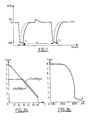
- - la figure 1 représente la forme d'onde d'une impulsion sur une période de récurrence de celle-ci,
- - la figure 2a représente la loi de variation de la durée de chaque impulsion, en fonction de la température de l'eau, et la figure 2b représente la loi de variation de la durée de chaque impulsion en fonction de la conductivité électrique de l'eau à traiter,
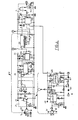
- - la figure 3 représente un schéma synoptique des blocs fontionnels constitutifs du dispositif de traitement de l'eau du réseau de distribution par impulsions électrique à durée modulée selon l'invention,
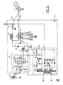
- - la figure 4 représente un mode de réalisation particulier non limitatif des moyens de mesure de débit, des moyens de mesure de température de l'eau, des moyens de mesure de la conductivité de l'eau et des moyens de modulation de la durée des impulsions en fonction de la température de l'eau,
- - la figure 5 représente un mode de réalisation non limitatif avantageux des moyens générateurs des impulsions de traitement,
- - la figure 6 représente un mode de réalisation particulier non limitatif de circuits plus particulièrement destinés à assurer l'affichage des paramètres d'état du dispositif,
- - la figure 7 représente en vue en coupe selon un plan de symétrie longitudinal un mode de réalsiation non limitatif d'une chambre de traitement conforme à l'objet de la présente invention.
- FIG. 1 represents the waveform of a pulse over a recurrence period of the latter,
- - Figure 2a represents the law of variation of the duration of each pulse, as a function of the water temperature, and Figure 2b represents the law of variation of the duration of each pulse as a function of the electrical conductivity of the water to be treated,
- FIG. 3 represents a block diagram of the functional blocks constituting the water treatment device of the distribution network by electric pulses of modulated duration according to the invention,
- - Figure 4 shows a particular non-limiting embodiment of the flow measurement means, means for measuring the water temperature, means for measuring the conductivity of the water and means for modulating the duration of the pulses depending on the water temperature,
- FIG. 5 represents an advantageous non-limiting embodiment of the means generating the processing pulses,
- FIG. 6 represents a particular nonlimiting embodiment of circuits more particularly intended for ensuring the display of the state parameters of the device,
- - Figure 7 shows in sectional view along a longitudinal plane of symmetry a non-limiting mode of realization of a treatment chamber according to the object of the present invention.
Le procédé de traitement de l'eau du réseau de distribution par impulsions électriques à durée modulée conforme à l'objet de la présente invention sera décrit avec les figures 1 et 2a et 2b.The process for treating the water in the distribution network by electric pulses of modulated duration in accordance with the object of the present invention will be described with FIGS. 1 and 2a and 2b.
Le problème de l'entartrage des canalisations ou organes de commande de réseaux de distribution d'eau domestiques ou industriels est lié à celui de l'équilibre calcocarbonique dans l'eau.The problem of scaling of pipes or organs control of domestic or industrial water distribution networks is linked to that of the calcocarbonic balance in water.
La solubilité du carbonate de calcium est régie par la loi d'action de masse, laquelle définit une constante d'équilibre dont la valeur dépend de la température et du degré d'ionisation de l'eau. Lorsque le produit des concentrations en ions calcium et bicarbonate est inférieur à cette constante, l'eau n'est pas saturée et est dite agressive car elle peut dissoudre du carbonate de calcium solide. Si ce produit est supérieur à cette constante, l'eau est au contraire susceptible d'engendrer un dépôt de carbonate de calcium et est dite calcifiante.The solubility of calcium carbonate is governed by the law of mass action, which defines an equilibrium constant whose value depends on the temperature and the degree of ionization of the water. When the product of the concentrations of calcium and bicarbonate ions is less than this constant, the water is not saturated and is said to be aggressive because it can dissolve solid calcium carbonate. If this product is greater than this constant, water is on the contrary capable of generating a deposit of calcium carbonate and is said to be calcifying.
Les diverses constantes qui déterminent les équilibres ioniques varient avec la température de l'eau et la solubilité du carbonate de calcium diminue lorsque la température augmente. Ainsi, une eau peut être agressive à froid et calcifiante après chauffage.The various constants which determine the ionic equilibria vary with the temperature of the water and the solubility of calcium carbonate decreases with increasing temperature. Thus, water can be aggressive when cold and calcifying after heating.
Une courbe d'équilibre calcocarbonique permet de définir les conditions d'équilibre entre une eau et du carbonate de calcium solide, mais ne permet pas de prévoir les conditions d'apparition de celui-ci sur la surface d'un matériau autre que le carbonate de calcium. L'apparition d'une particule de carbonate de calcium, désignée par germe, à la surface d'une paroi métallique nécessite que le produit des concentrations en ions calcium et en bicarbonate soit environ quarante fois supérieur à la constante d'équilibre.A calcocarbon equilibrium curve makes it possible to define the conditions of equilibrium between water and solid calcium carbonate, but does not make it possible to predict the conditions of appearance of the latter on the surface of a material other than carbonate calcium. The appearance of a particle of calcium carbonate, designated by germ, on the surface of a metal wall requires that the product of the concentrations of calcium ions and bicarbonate is approximately forty times greater than the equilibrium constant.
Le procédé objet de l'invention permet ainsi qu'il sera décrit ci-après dans la description, suite à un déplacement des équilibres carboniques de l'eau, compte-tenu notamment de la température de celle-ci, de rendre cette eau localement calcifiante par application d'impulsions électriques appropriées.The process which is the subject of the invention thus allows it to be described below in the description, following a shift in the carbon equilibria of the water, taking into account in particular the temperature thereof, to make this water locally calcifying by application of appropriate electrical pulses.
Le procédé de traitement physique de l'eau du réseau de distribution selon l'invention, consiste à appliquer à l'eau du réseau de distribution une série d'impulsions électriques d'amplitude constante et de fréquence de récurrence directement proportionnelle au débit de l'eau du réseau de distribution. A titre d'exemple non limitatif ainsi que représenté en figure 1, l'amplitude des impulsions est choisie de façon a appliquer à l'eau à traiter une différence de ptotentiel électrique de 50 Volts par centimètre d'épaisseur d'eau, les impulsions ayant une amplitude de 300 Volts. Conformément au procédé objet de l'invention, la durée des impulsions est modulée en fonction de la température de l'eau, de façon à provoquer pendant la durée de maintien de chaque impulsion, une floculation microscopique du carbonate de calcium contenu dans l'eau et la diffusion dans celle-ci des flocons microscopiques de carbonate de calcium en dehors de la durée de maintien de l'impulsion.The method of physical treatment of the water in the distribution network according to the invention consists in applying to the water of the distribution network a series of electrical pulses of constant amplitude and frequency of recurrence directly proportional to the flow of water from the distribution network. By way of nonlimiting example as shown in FIG. 1, the amplitude of the pulses is chosen so as to apply to the water to be treated a difference in electrical ptotential of 50 volts per centimeter of water thickness, the pulses having an amplitude of 300 Volts. In accordance with the process which is the subject of the invention, the duration of the pulses is modulated as a function of the temperature of the water, so as to cause, during the duration of maintenance of each pulse, microscopic flocculation of the calcium carbonate contained in the water. and the diffusion therein of microscopic flakes of calcium carbonate outside the duration of the pulse maintenance.
L'application d'une différence de potentiel ou champ électrique entre deux électrodes a pour effet de créer :
- une cathode au voisinage de laquelle ont lieu des réactions de réduction et en particulier celles de l'oxygène dissous
O₂ + 2H₂O + 4
- d'une anode, au voisinage de laquelle se produisent des réactions d'oxydation
2H₂O → O₂ + 4
Les ions O
- a cathode in the vicinity of which reduction reactions take place and in particular those of dissolved oxygen
WHERE + 2H₂O + 4
- an anode, in the vicinity of which oxidation reactions occur
2H₂O → WHERE + 4
O ions
Selon une autre caractéristique avantageuse du procédé objet de l'invention, la durée de chaque impulsion est inversement proportionnelle à la température de l'eau ainsi que représenté en figure 2a. Sur cette figure l'axe des abscisses est gradué en °C et l'axe des ordonnées en microsecondes. La durée des impulsions est comprise entre 5° et 60°.According to another advantageous characteristic of the process which is the subject of the invention, the duration of each pulse is inversely proportional to the temperature of the water as shown in FIG. 2a. In this figure, the abscissa axis is graduated in ° C and the ordinate axis in microseconds. The duration of the pulses is between 5 ° and 60 °.
Ainsi qu'on l'a également représenté en figure 2a la durée de chaque impulsion de traitement est modulee en fonction de la conductivité électrique de l'eau en vue de permettre une floculation microscopique du carbonate de calcium dans des conditions sensiblement stables de champ électrique appliqué à l'eau. Par conditions sensiblement stables de champ électrique appliqué à l'eau on entend notamment l'absence de claquage diélectrique et prise en compte par l'intermédiaire de la conductivité électrique précitée de l'eau de l'ionisation de celle-ci et notamment de la concentration en ions carbonates par exemple. Ainsi, sur la figure 2a on a représenté différentes courbes donnant le temps de maintien T1 des impulsions en fonction de la température pour diverses conductibilités électriques, la courbe en traits mixtes correspondant à une conductivité électrique σ ≦ 2 500 µ S, la courbe en continu correspondant au contraire à une eau de conductibilité σ = 4 700 µ S avec cependant une limitation de temps de maintien T1 à 5 micro secondes pour des températures de l'eau inférieures à 30°, afin d'éviter justement le risque d'apparation de claquage diélectrique de l'eau traitée.As also shown in FIG. 2a, the duration of each treatment pulse is modulated as a function of the electrical conductivity of the water in order to allow microscopic flocculation of the calcium carbonate under substantially stable electric field conditions. applied to water. By substantially stable conditions of the electric field applied to water is meant in particular the absence of dielectric breakdown and taken into account via the aforementioned electrical conductivity of the water of the ionization thereof and in particular of the concentration of carbonate ions for example. Thus, in FIG. 2a, various curves have been shown giving the holding time T1 of the pulses as a function of the temperature for various electrical conductivities, the curve in dashed lines corresponding to an electrical conductivity σ ≦ 2,500 µ S, the continuous curve on the contrary, corresponding to water with conductivity σ = 4,700 µ S with, however, a limitation of holding time T1 to 5 micro seconds for water temperatures below 30 °, in order to avoid the risk of dielectric breakdown appearing in the treated water.
Ainsi qu'on l'a représenté en figure 2b la durée de chaque impulsion de traitement c'est-à-dire le temps de maintien T1 de celle-ci est ainsi modulée selon une loi continument décroissante en fonction de la conductivité électrique de l'eau, conductivité électrique σ. La durée de chaque impulsion de traitement est ainsi comprise entre une et 8 microsecondes pour une conductivité électrique de l'eau comprise entre 5 000 µS et 2 500 µS, la durée T1 des impulsions de traitement étant modulée en fonction de cette conductivité ainsi que représenté en figure 2b.As shown in FIG. 2b, the duration of each processing pulse, that is to say the holding time T1 thereof, is thus modulated according to a continuously decreasing law as a function of the electrical conductivity of the 'water, electrical conductivity σ. The duration of each treatment pulse is thus between one and 8 microseconds for an electrical conductivity of the water between 5,000 µS and 2,500 µS, the duration T1 of the treatment pulses being modulated as a function of this conductivity as shown in Figure 2b.
En outre, ainsi qu'on l'a représenté en figure 1, chaque impulsion de traitement, impulsion négative, est suivie d'une impulsion de polarité opposée, impulsion positive, de façon à favoriser le décollement de germes ou flocons microscopique de carbonate de calcium susceptibles de se former sur la paroi de l'électrode jouant le rôle de cathode sur laquelle les impulsions de traitement négatives sont appliquées. De manière avantageuse, les impulsions négatives ont une amplitude de 300 Volts environ et les impulsions positive de polarité opposée ont une amplitude limitée à 50 Volts par exemple.In addition, as shown in FIG. 1, each treatment pulse, negative pulse, is followed by an opposite polarity pulse, positive pulse, so as to promote the detachment of microscopic carbonate germs or flakes. calcium likely to form on the wall of the electrode playing the role of cathode on which the negative treatment pulses are applied. Advantageously, the negative pulses have an amplitude of approximately 300 Volts and the positive pulses of opposite polarity have an amplitude limited to 50 Volts for example.
Une description plus détaillée d'un dispositif de traitement de l'eau du réseau de distribution par impulsions électriques conformément au procédé précédemment décrit sera maintenant donnée en liaison avec la figure 3.A more detailed description of a device for treating water in the distribution network by electrical pulses in accordance with the method described above will now be given in conjunction with FIG. 3.
Selon la figure précitée, le dispositif de traitement de l'eau du réseau de distribution par impulsions électriques conformément à l'objet de l'invention comprend une chambre 1 de traitement de l'eau dans laquelle l'eau du réseau de distribution est en circulation. Des moyens 2 de mesure du débit de l'eau et des moyens 3 générateurs d'impulsions électriques, désignées par les impulsions de traitement, sont prévus, les impulsions électriques de traitement étant appliquées à la chambre de traitement 1. La fréquence de récurrence des impulsions de traitement, soit en définitive la période τ de récurrence de ces impulsions, est proportionnelle au débit d'eau mesuré.According to the above-mentioned figure, the device for treating the water in the distribution network by electrical pulses in accordance with the subject of the invention comprises a
Ainsi qu'on l'a en outre représenté en figure 3, le dispositif objet de l'invention comporte de manière particulièrement avantageuse pour la mise en oeuvre du procédé précédemment décrit des moyens 4 de mesure de la température de l'eau, ces moyens délivrant un signal représentatif de cette température.As has also been shown in FIG. 3, the device which is the subject of the invention comprises, in a particularly advantageous manner for implementing the method described above, means 4 for measuring the temperature of the water, these means delivering a signal representative of this temperature.
Des moyens 5 de modulation de la durée des impulsions de traitement en fonction de la température sont prévus de façon à provoquer pendant la durée de maintien de chaque impulsion de traitement, durée notée T1, une floculation microscopique du carbonate de calcium contenu dans l'eau et la diffusion des flocons microscopiques de carbonate de calcium ainsi formés en dehors de la durée de maintien de l'impulsion de traitement. La diffusion des flocons microscopiques précités s'effectue dans l'eau distribuée par le réseau, ces flocons restant en suspension dans celui-ci.
En outre, le dispositif objet de l'invention comporte des moyens 6 de mesure de la conductivité électrique de l'eau et des moyens notés 50 de modulation de la durée des impulsions de traitement en fonction de la conductivité électrique de l'eau de façon à provoquer pendant la durée de maintien de chaque impulsion de traitement la floculation microscopique précitée du carbonate de calcium dans des conditions sensiblement stables de champ électrique appliquées à l'eau, et en particulier en l'absence de claquage diélectrique. La modulation de la durée de maintien des impulsions de traitement T1 en fonction de la conductivité électrique de l'eau traitée permet de prendre en compte le degré d'ionisation de l'eau et la durée de chaque impulsion de traitement, ou temps de maintien T1, est ainsi mdodulée selon une loi continument décroissante en fonction de la conductivité électrique de l'eau, conductivité notée σ. La durée de chaque impulsion de traitement est comprise entre 1 microseconde et 8 microsecondes pour une conductivité électrique de l'eau comprise entre 5 000 µS et 2 500 µS.In addition, the device which is the subject of the invention comprises means 6 for measuring the electrical conductivity of the water and means denoted 50 for modulating the duration of the treatment pulses as a function of the electrical conductivity of the water so to cause, during the holding time of each treatment pulse, the aforementioned microscopic flocculation of calcium carbonate under substantially stable conditions of electric field applied to water, and in particular in the absence of dielectric breakdown. Modulating the duration of treatment pulses T1 as a function of the electrical conductivity of the treated water makes it possible to take into account the degree of ionization of the water and the duration of each pulse of treatment, or holding time T1, is thus modulated according to a continuously decreasing law as a function of the electrical conductivity of the water, conductivity noted σ. The duration of each treatment pulse is between 1 microsecond and 8 microseconds for an electrical conductivity of the water between 5,000 µS and 2,500 µS.
Une description plus détaillée des différents organes précédemment décrits en liaison avec la figure 3 sera donnée en relation avec la figure 4.A more detailed description of the various bodies previously described in connection with FIG. 3 will be given in relation to FIG. 4.
Sur la figure 4 à titre de simplification, les résistances notées r et les capacités notées c désignent des résistances et des capacités nécessaires à la mise en oeuvre de composants électroniques normalement disponibles dans le commerce, ces résistances et ces capacités ne jouant aucun rôle fonctionnel particulier si ce n'est celui de la mise en oeuvre et en particulier de la polarisation convenable des circuits ou composants électroniques précités.In FIG. 4 by way of simplification, the resistors denoted r and the capacitors denoted c denote resistors and capacitors necessary for the implementation of electronic components normally available on the market, these resistors and these capacitors playing no particular functional role. if not that of the implementation and in particular of the suitable polarization of the aforementioned electronic circuits or components.
Ainsi qu'on l'a représenté sur cette figure, les moyens 2 de mesure du débit d'eau comprennent de façon non limitative une turbine Tu disposée dans la chambre de traitement 1 ainsi qu'il sera décrit plus en détail ultérieurement dans la description. Ils comportent également un capteur de vitesse 20 couplé à la turbine Tu, ce capteur de vitesse délivrant un signal périodique dont la fréquence est proportionnelle au débit d'eau. Le capteur de vitesse 20 peut être constitué par un détecteur à effet Hall commercialisé en France par la société SPRAGUE sous la référence UGN 3501T par exemple. Le capteur de vitesse délivre un signal périodique dont la fréquence est proportionnelle au débit d'eau, ce signal étant délivré à un étage d'amplification 21. L'étage d'amplification 21 est constitué par des élémements amplificateurs à transistors ou à amplificateurs opérationnels ainsi que représenté sur la figure 4 mais ne sera pas décrit en détail car la réalisation de cet amplificateur est à la portée de l'homme de métier.As shown in this figure, the
Les moyens 2 de mesure du débit d'eau comprennent en outre des moyens 22 de conversion fréquence/tension permettant de délivrer une tension continue proporionnelle au débit d'eau. Les moyens 22 de conversion fréquence/tension peuvent avantageusement être constitués par un circuit convertisseur commercialisé sous la référence 2917 N8 par la société NATIONAL SEMICONDUCTORS.The
Bien entendu, les moyens 22 de conversion fréquence/tension reçoivent le signal amplifié délivré par l'étage amplificateur 21.Of course, the frequency / voltage conversion means 22 receive the amplified signal delivered by the
En outre, les moyens 2 de mesure du débit d'eau comportent ainsi que représenté en figure 4 des moyens oscillateurs à fréquence commandée notés 23, les moyens oscillateurs à fréquence commandée recevant la tension continue proportionnelle au débit d'eau et délivrant un signal de commande dont la fréquence de récurrence est proportionnelle au débit d'eau. Les moyens oscillateurs à fréquence commandée 23 peuvent ainsi que représentés en figure 4 être constitués par un circuit intégré commercialisé sous la référence 566 par la société NATIONAL SEMICONDUCTORS. Ce circuit oscilateur à fréquence commandée noté 230 est un circuit diviseur 231 permettant en définitive de délivrer le signal de commande dont la fréquence de récurrence est proportionnelle au débit d'eau. Le circuit diviseur 231 peut être réalisé par un circuit commercialisé sous la référence 4017 par la société NATIONAL SEMICONDUCTORS.In addition, the
Une description plus détaillée des moyens 5 de modulation des impulsions de traitement en fonction de la température notamment sera donnée en liaison avec cette même figure 4.A more detailed description of the
Selon la figure précitée, les moyens 5 de modulation sont constitués par un circuit 50 variateur de rapport cyclique des impulsions de commande, les impulsions de commande étant bien entendu synchrones des impulsions de traitement ainsi qu'il sera expliqué ultérieurement dans la description. Ainsi, le rapport cyclique des impulsions de traitement est défini par le rapport ![]()
![]()
Une description plus détaillée des moyens 4 de mesure de la température de l'eau sera maintenant donnée également en liaison avec la figure 4.A more detailed description of the
Conformément à la figure précitée, les moyens 4 de mesure de la température de l'eau comportent avantageusement une sonde 40 de mesure de température placée dans la chambre de traitement 1, cette sonde délivrant un signal de tension continue représentative de la température de l'eau. La sonde de mesure de température peut avantageusement être constituée par une sonde commercialisée par la société NATIONAL SEMICONDUCTORS sous la référence LM35.In accordance with the above-mentioned figure, the
En outre, les moyens 4 de mesure de la température comportent également un oscilateur 41 à fréquence commandée, cet oscilateur recevant sur une entrée de commande le signal de tension continue représentatif de la température de l'eau et délivre un signal périodique dont la fréquence est proportionnelle à la température de l'eau. L'oscillateur à fréquence commandée 41 peut avantageusement être consititué par un composant commercialisé sous la référence LM331 par la Société NATIONAL SEMICONDUCTORS. Le signal continu délivré par la sonde 40 est appliqué sur l'entré n° 7 du circuit précité.In addition, the
En outre, les moyens 4 de mesure de température comportent enfin un circuit 42 convertisseur frquence/tension recevant le signal périodique délivré par l'oscillateur à fréquence commandée 41 et délivrant sur une borne de sortie une tension continue constituant le signal représentatif de la température de l'eau délivré par les moyens 4 de mesure de température. A titre d'exemple non limitatif, ainsi que représenté en figure 4, le circuit 42 convertisseur fréquence/tension peut être constitué par un circuit commercialisé sous la référence 2917 N8 par la Société NATIONAL SEMICONDUCTORS. La borne de sortie délivrant le signal représentatif de la température de l'eau est alors la borne n° 5.In addition, the temperature measurement means 4 finally comprise a frequency /
La borne de sortie n° 5 du circuit constituant circuit 42 convertisseur de fréquence/tension des moyens de mesure de température 4 est alors connectée par l'intermédiaire d'un potentiomètre de réglage noté 420 à la borne d'entrée de polarisation 5 du circuit 50 variateur de rapport cyclique des impulsions de commande.The output terminal No. 5 of the circuit constituting the
Ainsi, le mode de réalisation représenté en figure 4 des moyens de mesure de débit 2, des moyens 4 de mesure de température et des moyens 5 de modulation de la durée des impulsions de traitement en fonction de la température, permet de réaliser une modulation de la durée T1 des impulsions de traitement, bien entendu par la modulation correspondante du rapport cyclique des impulsions de commande, en fonction de la température de l'eau.Thus, the embodiment represented in FIG. 4 of the flow measurement means 2, of the temperature measurement means 4 and of the
Une description plus détaillée des moyens 3 générateurs d'impulsions électriques de traitement sera maintenant donné en liaison avec la gigure 5.A more detailed description of the
Selon la figure précitée, les moyens 3 générateurs d'impulsions comportent avantageusement des moyens 30 générateurs d'une haute tension continue d'alimentation. Les moyens 30 précités permettent d'engendrer une tension de l'ordre de 300 Volts et peuvent être constitués par tout système d'alimentation redressée permettant d'engendrer une tension continue à potentiel flottant par rapport à la masse. Par potentiel flottant par rapport à la masse on comprend un système ainsi que représenté en figure 3 dans lequel les enroulements secondaires du transformateur d'alimentation, transformateur 300, ne sont pas connectés à un potentiel de référence tel que la masse, le potentiel positif, borne + et négatif, borne - de la tension redressée délivrée par les moyens 30 générateurs de haute tension continue n'etant pas définis par rapport à la masse du dispositif. Ainsi l'amplitude de 300 Volts de la tension continue engendrée par les moyens 30 générateurs de haute tension continue est définie entre la borne positive et la borne négative de sortie des moyens 30 générateurs précités. Une description détaillée des moyens 30 générateurs de haute tension continue n'est pas nécessaire dans la mesure où ce type d'alimentation haute tension continue est connu de l'homme de métier.According to the aforementioned figure, the
En outre, les moyens générateurs d'impulsions électriques de traitement comportent des moyens de commutation 31 constitués par un transistor C-MOS de puissance, ces moyens de commutation étant connectés en parallèle sur une capacité 32, la borne de source du transistor de commutation MOS de puissance étant connectée à l'une des bornes de la capacité et la borne de drain du transistor de commutation 31 étant connectée à l'autre borne de la capacité 32 par l'intermédiaire d'une diode de protection notée 33. Les moyens de commutation 31 constiués par le transistor MOS de commutation comportent une borne d'entrée de commande constituée par la borne de grille du transistor MOS. La borne de source du transistor MOS de commutation 31 est connectée à la borne négative des moyens 30 générateurs de haute tension continue d'alimentation.In addition, the means for generating electrical processing pulses comprise switching means 31 constituted by a power C-MOS transistor, these switching means being connected in parallel on a capacitor 32, the source terminal of the MOS switching transistor. of power being connected to one of the terminals of the capacitor and the drain terminal of the switching
Les moyens 3 générateurs d'impulsions de traitement comportent également un circuit de charge de la capacité 32 permettant d'engendrer les impulsions de traitement. Le circuit de charge comporte un transformateur 34 dont l'enroulement primaire est en série avec une borne de connection 340 permettant de connecter la chambre de traitement 1 et en particulier l'électrode périphérique de celle-ci, ainsi qu'il sera décrit ultérieurement dans la description, en série dans le circuit de charge de la capacité 32. Par connexion en série de la chambre de traitement, ainsi que réprésenté en figure 5, on comprendra que la résistance équivalente comprise entre l'électrode périphérique et l'électrode centrale de la chambre de traitement, résistance équivalente constituée par l'eau à traiter, est connectée en série entre la borne de connexion 340 précitée et par exemple une autre borne 341, laquelle est reliée au potentiel de référence de masse du dispositif. Le circuit de charge de la capacité 32 est alors refermé par l'intermédiaire d'une résistance 37 dont la fonction sera explicitée ultérieurement dans la description, cette résistance étant connectée à la tension de référence de masse du dispositif d'une part et à la borne positive de sortie des moyens générateurs de haute tension d'alimentation 30.The
En outre, les moyens 3 générateurs d'impulsions électriques de traitement comportent des moyens optoélectroniques récepteurs 35, lesquels sont bien entendu couplés aux moyens optoélectronique émetteurs 51 des moyens de modulation 5 de la durée des impulsions de commande. Les moyens optoélectroniques récepteurs 35 comprennent par exemple un phototransistor récepteur 350 auquel est connecté sur l'électrode de collecteur de celui-ci une série d'inverseurs 351 afin d'obtenir une sortie basse impédence du phototransistor 350. Bien entendu, la sortie basse impédence de l'ensemble des circuits 351 est connectée à la borne de grille constituant borne d'entrée de commande des moyens de commutation constitués par le transistor C-MOS de commutation 31. On notera en outre que, outre les enroulements nécessaires pour engendrer la haute tension continue redressée HT égale à 300 Volts, le transformateur d'alimentation 300 comporte un enroulement 301 auxiliaire, lequel permet d'engendrer une tension continue d'alimentation notée VCC, laquelle permet d'alimenter notamment le phototransistor 350.In addition, the
Le fonctionnement du dispositif tel que représenté en figures 4 et 5 est le suivant :
- la fréquence de récurrence des impulsions de commande, et en définitive la fréquence de récurrence des impulsions de traitement est commandée par la mesure du débit effectuée par la turbine Tu et par la chaîne consituant les moyens 2 de mesure de débit. Pour un débit d'eau stable, la fréquence de récurrence des impulsions de commande et des impulsions de traitement est fixe et les impulsions de commande transmises par les moyens modulateurs de durée des impulsions constituant variateur de rapport cyclique des impulsions de commande permet alors, à partir de l'information transmise par les moyens 4 de mesure de température, de moduler en conséquence la durée de maintient T1 des impulsions de traitement par l'intermédiaire de la commande du rapport cyclique des impulsions de commande. Les impulsions de commande sont transormées en impulsions lumineuses par la diode électroluminescente 51 et ces impulsions lumineuses sont reçues par le phototransistor 350 couplé à la diode électroluminescente précitée. Les impulsions électriques délivrées par le phototransistor 350 sont alors transmises par les circuits basse impédance 351 à la borne de commande des moyens de commutation 31, lesquels permettent alors la décharge quasi instantannée en quelques microsecondes de la capacité 32 par mise en cours circuit des moyens de commutation ou transistors C-MOS 31. La mise en court-circuit des transistors 31 de commutation et de la capacité 32 est maintenue pendant le temps de maintien T1 formant ainsi le temps de maintien de l'impulsion de traitement. Sur rebasculement de l'impulsion de commande, le transistor C-MOS de commutation 31 est à nouveau bloqué et la capacité 32 se recharge avec une constante de temps correspondant sensiblement à celle de cette capacité 32 connectée en série avec la résistance équivalente de la chambre de traitement 1, la résistance de faible valeur 37 et la résistance de l'enroulement primaire du transformateur 34. On notera que le transformateur 34 est utilisé afin d'obtenir des informations sur les enroulements secondaires de celui-ci, relatives à l'intensité du courant électrique transitant dans la chambre de traitement 1 en vue d'affichage des paramètres d'état du dispositif au cours du traitment de l'eau ainsi qu'il sera décrit ultérieurement dans la description.The operation of the device as shown in Figures 4 and 5 is as follows:
the frequency of recurrence of the control pulses, and ultimately the frequency of recurrence of the treatment pulses is controlled by the measurement of the flow rate carried out by the turbine Tu and by the chain constituting the
Afin d'engendrer l'impulsion de polarité opposée à l'impulsion de traitement, impulsion de polarité opposée suivant chaque impulsion de traitement, les moyens générateurs 3 d'impulsion de traitement comportent en outre connectés en parallèle sur le circuit de charge une self inductance 36 constituant avec la capacite 32 un circuit résonnant amorti. Ce circuit résonnant amorti permet d'engendrer suite à la charge de la capacité 32 l'impulsion de polarité opposée à l'impulsion de décharge de la capacité formant l'impulsion de traitement. Le circuit résonnant amorti ainsi constitué a pour effet d'engendrer une oscillation amortie dont le premier maximum se superpose à la courbe de charge de la capacité 32 pour constituer ainsi le pic de polarité opposée à l'impulsion de traitement.In order to generate the pulse of opposite polarity to the processing pulse, pulse of opposite polarity according to each processing pulse, the
Une description plus détaillée des moyens 6 de mesure de la conductivité électrique de l'eau sera maintenant donnée en liaison avec la figure 5 et la figure 4.A more detailed description of the
Selon la figure 5 précitée, les moyens 6 de mesure de la conductivité électrique de l'eau sont constitués par la résistance 37 de faible valeur représentée en figure 5. Cette résistance permet d'engendrer un signal de tension proportionnel au courant électrique circulant dans la chambre de traitement 1.According to FIG. 5 above, the
En outre, ainsi que représenté en figure 4, les moyens 6 de mesure de la conductivité électrique de l'eau comportent un circuit redresseur noté 60, 61 constitué par des diodes, ce circuit redresseur étant connecté aux bornes de la résistance 37 et permettant d'engendrer une tension continue proportionnelle au courant électrique circulant dans la chambre de traitement. Le circuit redresseur 60, 61 est connecté à une entrée de commande de polarisation du circuit 42 convertisseur de fréquence/tension des moyens de mesure de la température de l'eau 4.In addition, as shown in FIG. 4, the
Le fonctionnement du dispositif tel que représenté en figure 4 et 5 est le suivant :
- lors de la variation de la conductivité électrique σ de l'eau, les impulsions de traitement étant d'amplitude sensiblement constante égale à 300 Volts, le courant circulant dans le circuit de charge de la capacité 32 et en définitive dans la chambre de traitment 1 varie en conséquence et produit au niveau des bornes de la résistance de faible valeur 37 une différence de potentiel correspondante et représentative de cette intensité. Le circuit redresseur 60, 61 délivre alors une tension redressée continue proportionnelle au courant électrique circulant dans la chambre de traitement. Cette tension a pour effet de modifier la polarisation du convertisseur fréquence/tension 42 des moyens de mesure de la température de l'eau, ce qui a pour effet de modifier la tension de sortie délivrée par le potentiomètre 420, tension destinée à moduler le rapport cyclique des impulsions de commande au niveau du circuit variateur de rapport cyclique des impulsions de commande 50.The operation of the device as shown in FIGS. 4 and 5 is as follows:
- during the variation of the electrical conductivity σ of the water, the treatment pulses being of substantially constant amplitude equal to 300 Volts, the current flowing in the charge circuit of the capacity 32 and ultimately in the
Ainsi, le mode de réalisation des figures 4 et 5 permet de réaliser une modulation de la durée T1 de maintien des impulsions de traitement conformément aux lois de variations représentées aux figures 2a et 2b précédemment décrites dans la description.Thus, the embodiment of Figures 4 and 5 allows for a modulation of the duration T1 of maintaining the processing pulses in accordance with the laws of variations shown in Figures 2a and 2b previously described in the description.
Afin de faciliter l'utilisation par l'abonné du dispositif objet de l'invention, celui-ci comporte ainsi que représenté en figure 3 des moyens d'affichage 7, 8 des paramètres de fonctionnement du dispositif, paramètres tels que le débit d'eau, la température de l'eau, la fréquence des impulsions de traitement, la mise sous tension du dispositif ou la mise hors tension de celui-ci, une alarme de mise en défaut de dispositif par exemple.In order to facilitate the subscriber's use of the device which is the subject of the invention, it comprises, as shown in FIG. 3, means 7, 8 for displaying the operating parameters of the device, parameters such as the flow of water, water temperature, frequency of treatment pulses, switching the device on or off, a device fault alarm for example.
Dans ce but, les moyens d'affichage précités, ainsi que représentés en figure 6, comportent par exemple un multiplexeur 70 recevant les signaux représentatifs des paramètres précités en parallèle. Ces signaux peuvent avantageusement être constitués par les signaux de fréquence 12, 13 délivrés respectivment par l'oscillateur à fréquence commandée 230 et par l'oscillateur à fréquence commandée 41, ces signaux étant respectivement représentatifs du débit d'eau et de la température de l'eau. Les autres signaux peuvent être constitués également par des signaux de fréquence correspondants mais ces signaux ne seront pas décrits et les circuits correspondants susceptibles de les engendrer ne seront pas non plus décrits car ils correspondent à des modes de réalisation à portée de l'homme de métier. Les multiplexeurs 70 délivrent des signaux codés en séquence série sous forme d'impulsions codées. Le multiplexeur 70 ne sera pas décrit car il correspond à un multiplexeur de type classique, lequel est parfaitement connu de l'homme de métier dans son principe.For this purpose, the aforementioned display means, as shown in FIG. 6, comprise for example a
En outre, les moyens d'affichage 7, 8 comportent des moyens 71 de mise en forme des impulsions codées. Les moyens de mise en forme des impulsions codées reçoivent les signaux délivrés par le multiplexeur 70, c'est-à-dire les impulsions codées, et ils comportent, relié à une borne d'alimentation de tension continue 2VCC par exemple par l'intermédiaire d'une self inductance assurant un filtrage avec une capacité 711, un transistor de commutation de type C-MOSnoté 712 dont la borne de grille est connectée à la borne d'entrée des impulsions codées, dont la borne de drain est connectée à la self inductance 710 et dont la borne de source est connectée à la borne de sortie des impulsions mises en forme. Une diode Zéner 71 est connectée en parallèle entre la borne de source et la borne de grille du transistor de commutation 712. Une résistance de charge 714 est connectée entre la borne de drain et la borne de source du transistor de commutation 712. Le circuit de mise en forme permet de réduire le niveau des impulsions codées à un niveau de l'ordre de 2 Volts par exemple.In addition, the display means 7, 8 include means 71 for formatting the coded pulses. The means for shaping the coded pulses receive the signals delivered by the
En outre, un organe d'affichage satellite 8 ainsi que représenté en figure 1 est prévu. L'organe d'affichage satellite 8 comporte un circuit décodeur des impulsions codées, lequel ne sera pas décrit car il correspond à un sytème décodeur connu pour le décodage d'impulsions multiplexées codées. L'organe d'affichage satellite 8 est relié aux moyens de mise en forme 71 par l'intermédiaire d'une prise coaxiale par exemple. Ainsi, l'organe d'affichage satellite 8 peut avantageusement être soit enfiché directement sur la prise coaxiale, l'organe d'affichage satellite 8 étant alors solidaire du dispositif et en particulier du coffret de celui-ci ou au contraire être relié aux moyens de mise en forme 71 par l'intermédiaire d'un câble coaxial, le câble coaxial pouvant être un câble coaxial de grande longueur, jusqu'à 100 mètres. Ainsi, le dispositif objet de l'invention peut être installé dans les dépendances de la maison d'un abonné domestique et l'organe d'affichage satellite peut au contraire être installé dans un vestibule ou dans un endroit approprié de la zone d'habitation.In addition, a
Une description plus détaillée de la chambre de traitement 1 sera maintenant donnée en liaison avec la figure 7.A more detailed description of the
Selon la figure précitée, la chambre de traitment 1 comporte une électrode cylindrique périphérique 10 à laquelle sont appliquées les impulsions de traitement. Elle comporte également une électrode cylindrique centrale 11 reliée à la tension de référence ou masse du dispositif. Une enveloppe 12 en matériau isolant électrique entoure l'électrode cylindrique périphérique 10 et constitue une enceinte étanche pour l'eau à traiter. En outre, un premier 13 et deuxième 14 blocs d'extrémités consitituent parois frontales de la chambre de traitement, chaque bloc d'extrémité 13 et 14 étant muni d'une canalisation centrale 131, 141 d'arrivée ou de départ de l'eau de la chambre de traitement. L'étanchéité de la chambre de traitement peut être assurée entre l'électrode périphérique 10 et les premier et deuxième blocs d'extrémités 13 et 14 par l'intermédiaire de joints d'étanchéité 101, 102. L'enveloppe en matériau isolant électrique peut être constituée avantageusement par une enveloppe en polychlorure de vynile ou PVC.According to the above-mentioned figure, the
Ainsi qu'on l'a représenté en outre en figure 7, le bloc d'extrémité 13 comportant la canalisation centrale d'arrivée 131 est muni sur cette canalisation de la turbine Tu de mesure du débit d'eau.As has also been shown in FIG. 7, the
En outre, l'électrode cylindrique centrale 11 présente une extrémité solidaire du deuxième bloc d'extrémité 14. Selon un mode de réalisation avantageux non limitatif, l'électrode centrale est partielle ment creuse pour constituer canalisation de départ 141 de l'eau, cette électrode creuse étant munie au voisinage du deuxième bloc d'extrémité d'orifices traversants 110 mettant en communication la chambre de traitement 1 et la canalisation de départ 141. L'autre extrémité 111 de l'électrode centrale 11 est placée au voisinage du premier bloc d'extrémité 13 et de la turbine Tu.In addition, the central
Ainsi qu'on l'a représenté en outre sur la figure 7, l'extrémité 111 de l'électrode centrale placée au voisinage de la turbine Tu présente une forme tronconique afin d'assurer une répartition aléatoire des veines d'eau au sortir de la turbine. Par répartition aléatoire des veines d'eau au sortir de la turbine on comprendra que les veines d'eau au sortir de la turbine rencontrant l'extrémité tronconique précitée ne sont soumises à aucun trajet préférentiel susceptible de créer, au niveau de l'écoulement de l'eau, une inhomogénéité susceptible d'entraîner un traitement différent en fonction des zones correspondantes. On notera en fait que la turbine Tu utilisée est une turbine non susceptible de créer des turbulences avant l'entrée de l'eau de chambre de traitement 1.As shown in addition in FIG. 7, the
Afin d'augmenter le caractère aléatoire précité, de l'écoulement, la paroi de l'extrémité 111 de forme tronconique de l'électrode cyclindrique centrale 11 est munie de rainures hélicoïdales et l'extrémité de l'électrode centrale 11 est montée à rotation libre autour de l'axe longitudinal Δ de symétrie de la chambre de traitement 1 et de l'électrode centrale 11.In order to increase the aforementioned randomness of the flow, the wall of the
On a ainsi décrit un procédé et un dispositif de traitement physique de l'eau du réseau de distribution particulièrement efficace dans la mesure où celui-ci prend en compte pour le traitment physique par impulsions électriques de l'eau de distribution des paramètres physiques de celle-ci tels que la température et la conductivité électrique.We have thus described a method and a device for the physical treatment of water from the distribution network which is particularly effective insofar as it takes into account for the physical treatment by electrical pulses of the water for distribution of the physical parameters of that - such as temperature and electrical conductivity.
La mise en oeuvre du procédé objet de l'invention au moyen du dispositif précédemment décrit a pour effet de réduire très fortement les problèmes d'entartrage de canalisations notamment des canalisations de circuit de production d'eau chaude ou de chauffage d'installations domestiques ou industrielles. Le procédé et le dispositif objet de l'invention peuvent également être utilisés pour le traitement des eaux alimentaires, le procédé objet de l'invention ayant tout au plus comme effet une légère augmentation de la turbidité de l'eau en raison de la floculation microscopique du carbonate de calcium et de la diffusion de celui-ci dans l'eau de distribution.The implementation of the process which is the subject of the invention by means of the device described above has the effect of greatly reducing the problems of scaling of pipes, in particular pipes for the circuit for producing hot water or for heating domestic installations or industrial. The method and the device which are the subject of the invention can also be used for the treatment edible water, the process which is the subject of the invention having at most the effect of a slight increase in the turbidity of the water due to the microscopic flocculation of calcium carbonate and of the diffusion thereof in the water of distribution.
Claims (18)
- des moyens (4) de mesure de la température de l'eau délivrant un signal représentatif de ladite température,
- des moyens (5) de modulation de la durée des impulsions de traitement en fonction de la température de fàçon à provoquer, pendant la durée de maintien de chaque impulsion de traitement, une floculation microscopique du carbonate de calcium contenu dans l'eau et la diffusion des flocons microscopiques de carbonate de calcium en dehors de la durée de maintien de l'impulsion de traitement.5. Device for treating the water in the distribution network by electric pulses of modulated duration, comprising a chamber (1) for treating the water in which the water from the distribution network is in circulation, means (2) for measuring the water flow and means (3) generating electrical pulses called treatment pulses applied to said treatment chamber (1) and the frequency of recurrence of which is proportional to the measured water flow, characterized in that '' it also includes:
- means (4) for measuring the temperature of the water delivering a signal representative of said temperature,
means (5) for modulating the duration of the treatment pulses as a function of the temperature of the method to cause, during the maintenance period of each treatment pulse, microscopic flocculation of the calcium carbonate contained in the water and the diffusion of microscopic flakes of calcium carbonate outside the duration of maintenance of the treatment pulse.
- des moyens (6) de mesure de la conductivité électrique de l'eau,
- des moyens (50) de modulation de la durée des impulsions de traitement en fonction de la conductivité électrique de l'eau de façon à provoquer, pendant la durée de maintien de chaque impulsion de traitement, une floculation microscopique du carbonate de calcium dans des conditions sensiblement stables de champ électrique appliqué à l'eau, notamment en l'absence de risque de claquage diélectrique, la durée de chaque impulsion de traitement étant modulée selon une loi continument décroissante en fonction de la conductivité électrique de l'eau, la durée de chaque impulsion de traitement étant comprise entre 1µs et 8µs pour une conductivité électrique de l'eau comprise entre 5 000µS et 2 500 µS.6. Device according to claim 5, characterized in that it further comprises:
- means (6) for measuring the electrical conductivity of the water,
- Means (50) for modulating the duration of the treatment pulses as a function of the electrical conductivity of the water so as to cause, during the maintenance period of each treatment pulse, microscopic flocculation of the calcium carbonate in substantially stable conditions of the electric field applied to water, in particular in the absence of risk of dielectric breakdown, the duration of each treatment pulse being modulated according to a continuously decreasing law as a function of the electrical conductivity of the water, the duration of each treatment pulse being between 1µs and 8µs for an electrical conductivity of the water between 5,000µS and 2,500 µS.
- une turbine (Tu) disposée dans la chambre de traitement (1),
- un capteur de vitesse (20) couplé à ladite turbine (Tu), ledit capteur de vitesse délivrant un signal périodique dont la fréquence est proportionnelle au débit d'eau,
- des moyens (22) de conversion fréquence-tension permettant de délivrer une tension continue proportionnelle au débit d'eau,
- des moyens oscillateurs à fréquence commandée (23) recevant ladite tension continue proporitonnelle au débit d'eau et délivrant un signal de commande dont la fréquence de récurrence est proporitonnelle au débit d'eau.7. Device according to claim 5, characterized in that the means (2) for measuring the water flow rate comprise:
- a turbine (Tu) arranged in the treatment chamber (1),
- a speed sensor (20) coupled to said turbine (Tu), said speed sensor delivering a periodic signal whose frequency is proportional to the water flow,
- frequency-voltage conversion means (22) making it possible to deliver a direct voltage proportional to the water flow,
- Frequency controlled oscillator means (23) receiving said proportional DC voltage at the water flow rate and delivering a control signal whose recurrence frequency is proportional to the water flow rate.
- une sonde (40) de mesure de température placée dans la chambre de traitement (1), ladite sonde délivrant un signal de tension continue représentative de la température de l'eau,
- un oscillateur (41) à fréquence commandée recevant sur une entrée de commande ledit signal de tension continue représentative de la température de l'eau et délivrant un signal périodique dont la fréquence est proportionnelle à la température de l'eau,
- un circuit (42) convertisseur fréquence-tension recevant ledit signal périodique et délivrant sur une borne de sortie une tension continue constituant ledit signal représentatif de la température de l'eau délivré par les moyens de mesure de température.9. Device according to claims 5, 7 and 8, characterized in that said means (4) for measuring the water temperature comprise:
a temperature measurement probe (40) placed in the treatment chamber (1), said probe delivering a DC voltage signal representative of the water temperature,
- a frequency controlled oscillator (41) receiving on a control input said DC voltage signal representative of the water temperature and delivering a periodic signal whose frequency is proportional to the water temperature,
- A frequency-voltage converter circuit (42) receiving said periodic signal and delivering on a output terminal a DC voltage constituting said signal representative of the temperature of the water delivered by the temperature measurement means.
- des moyens (30) générateurs d'une haute tension continue d'alimentation,
- des moyens de commutation (31) connectés en parallèle sur une capacité (32) et comportant une borne d'entrée de commande,
- un circuit de charge de ladite capacité (32) permettant d'engendrer lesdites impulsions de traitement, ledit circuit de charge comportant une borne de connexion permettant de connecter la chambre de traitement (1) en série dans le circuit de charge de ladite capacité,
- des moyens optoélectroniques récepteurs (35) coupl̂és aux moyens optoélectroniques émetteurs (51) des moyens de modulation (5) de la durée des impulsions, lesdits moyens optoélectroniques récepteurs étant connectés à ladite borne d'entrée de commande des moyens de commutation (31).10. Device according to one of claims 5 to 9, characterized in that said means (3) generating electrical treatment pulses comprise:
means (30) for generating a high continuous supply voltage,
- switching means (31) connected in parallel on a capacitor (32) and comprising a control input terminal,
a charging circuit for said capacity (32) making it possible to generate said treatment pulses, said charging circuit comprising a connection terminal making it possible to connect the treatment chamber (1) in series in the charging circuit for said capacity,
- receiving optoelectronic means (35) coupled to the sending optoelectronic means (51) of the pulse duration modulation means (5), said receiving optoelectronic means being connected to said control input terminal of the switching means (31) .
-une résistance (37) de faible valeur connectée en série dans ledit circuit de charge, permettant d'engendrer un signal de tension proportionnel au courant électrique circulant dans la chambre de traitement (1),
- un circuit redresseur (60, 61) connecté aux bornes de ladite résistance (37) permettant d'engendrer une tension continue proportionnelle audit courant électrique circulant dans la chambre de traitement, ledit circuit redresseur (60, 61) étant connecté à une entrée de commande de polarisation dudit circuit (42) convertisseur fréquence-tension des moyens de mesure de la température de l'eau.12. Device according to claims 6, 10 and 11, characterized in that said means (6) for measuring the electrical condictivity of water consist of:
a resistor (37) of low value connected in series in said charging circuit, making it possible to generate a voltage signal proportional to the electric current flowing in the processing chamber (1),
- a rectifier circuit (60, 61) connected to the terminals of said resistor (37) making it possible to generate a direct voltage proportional to said electric current flowing in the treatment chamber, said rectifier circuit (60, 61) being connected to an input of polarization control of said frequency-voltage converter circuit (42) of the water temperature measurement means.
- un multiplexeur (70) recevant les signaux représentatifs desdits paramètres en parallèle et délivrant lesdits signaux codés en séquence série, sous forme d'impulsions codées,
- des moyens (71) de mise en forme des impulsions codées,
- un organe d'affichage satellite (8) relié auxdits moyens de mise en forme (71) par une prise coaxiale.13. Device according to one of the preceding claims, characterized in that it further comprises display means (7, 8) of the operating parameters of the device such as water flow rate, water temperature, frequency processing pulses, powering up of the device, alarm, said display means comprising:
a multiplexer (70) receiving the signals representative of said parameters in parallel and delivering said coded signals in serial sequence, in the form of coded pulses,
- means (71) for shaping the coded pulses,
- a satellite display member (8) connected to said shaping means (71) by a coaxial socket.
- une électrode cylindrique périphérique (10) à laquelle sont appliquées les impulsions de traitement,
- une électrode cylindrique centrale (11) reliée à la tension de référence ou masse du dispositif,
- une enveloppe (12) en matériau isolant électrique entourant ladite électrode cylindrique périphérique (10) et constituant enceinte étanche pour l'eau à traiter, un premier (13) et un deuxième (14) bloc d'extrémité constituant paroi frontale de la chambre de traitement (1), chaque bloc d'extrémité (13, 14) étant muni d'une canalisation centrale (131, 141) d'arrivée ou de départ de l'eau de la chambre de traitement.14. Device according to one of the preceding claims, characterized in that said treatment chamber (1) comprises:
- a peripheral cylindrical electrode (10) to which the treatment pulses are applied,
- a central cylindrical electrode (11) connected to the reference voltage or ground of the device,
- an envelope (12) of electrical insulating material surrounding said peripheral cylindrical electrode (10) and constituting a sealed enclosure for the water to be treated, a first (13) and a second (14) end block constituting the front wall of the chamber treatment (1), each end block (13, 14) being provided with a central pipe (131, 141) for the arrival or departure of water from the treatment chamber.
Priority Applications (1)
| Application Number | Priority Date | Filing Date | Title |
|---|---|---|---|
| AT89401021T ATE64581T1 (en) | 1988-04-15 | 1989-04-13 | METHOD AND DEVICE FOR TREATMENT OF TAP WATER BY MEANS OF ELECTRICAL PULSE OF MODULATED DURATION. |
Applications Claiming Priority (2)
| Application Number | Priority Date | Filing Date | Title |
|---|---|---|---|
| FR8805004A FR2630100B1 (en) | 1988-04-15 | 1988-04-15 | METHOD AND DEVICE FOR TREATING WATER IN THE DISTRIBUTION NETWORK BY MODULATED DURATION ELECTRIC PULSES |
| FR8805004 | 1988-04-15 |
Publications (2)
| Publication Number | Publication Date |
|---|---|
| EP0338896A1 true EP0338896A1 (en) | 1989-10-25 |
| EP0338896B1 EP0338896B1 (en) | 1991-06-19 |
Family
ID=9365342
Family Applications (1)
| Application Number | Title | Priority Date | Filing Date |
|---|---|---|---|
| EP89401021A Expired - Lifetime EP0338896B1 (en) | 1988-04-15 | 1989-04-13 | Method and apparatus for treating tap water by electrical modulated duration pulses |
Country Status (5)
| Country | Link |
|---|---|
| EP (1) | EP0338896B1 (en) |
| AT (1) | ATE64581T1 (en) |
| DE (1) | DE68900121D1 (en) |
| ES (1) | ES2023722B3 (en) |
| FR (1) | FR2630100B1 (en) |
Cited By (10)
| Publication number | Priority date | Publication date | Assignee | Title |
|---|---|---|---|---|
| FR2666801A1 (en) * | 1990-09-14 | 1992-03-20 | Mercier Dominique | PROCESS AND APPARATUS FOR TREATING WATER BY ELECTROLYSIS, IN PARTICULAR WITH A VIEW OF ITS DECARBONATION. |
| EP0667834A1 (en) * | 1992-09-25 | 1995-08-23 | BARNES, Clive | Preventing contaminant build-up in beer lines |
| FR2727104A1 (en) * | 1994-11-18 | 1996-05-24 | Mercier Dominique | Electrolysis of water to remove carbonate |
| WO1996029145A1 (en) * | 1995-03-19 | 1996-09-26 | Hugo Lucca | Process and device for electromagnetic fluid treatment |
| DE19602369A1 (en) * | 1996-01-24 | 1997-07-31 | Edwin Ell | Treatment of electrically conductive liquid, especially hard water |
| GB2367106A (en) * | 2000-09-23 | 2002-03-27 | Ian Lee | Method and apparatus for the treatment of conduits by means of a pulsed or varying energy input signal |
| WO2009023428A2 (en) * | 2007-08-10 | 2009-02-19 | Freije Treatment Systems, Inc. | Fluid treatment device with alternating electric potential difference |
| ITMI20092038A1 (en) * | 2009-11-19 | 2011-05-20 | Antical S R L | EQUIPMENT FOR WATER HARDNESS CONTROL, FOR WATER DISTRIBUTION SYSTEMS IN GENERAL. |
| RU2714065C1 (en) * | 2019-07-02 | 2020-02-11 | Федеральное государственное бюджетное научное учреждение "Федеральный научный агроинженерный центр ВИМ" (ФГБНУ ФНАЦ ВИМ) | Drinking water and waste water treatment device |
| RU2723847C1 (en) * | 2019-11-07 | 2020-06-17 | Общество с ограниченной ответственностью "СтройПромБезопасность" | Device for cleaning of internal surface of pipes and heat exchange equipment by variable magnetic field |
Families Citing this family (3)
| Publication number | Priority date | Publication date | Assignee | Title |
|---|---|---|---|---|
| DE102011005506A1 (en) * | 2011-03-14 | 2012-09-20 | Judo Wasseraufbereitung Gmbh | Method for operating an electrolytic water treatment device, in particular for limescale protection |
| DE202015002004U1 (en) | 2015-03-13 | 2015-04-24 | Pauly Gmbh | Water treatment device without chemical dosing for the removal and prevention of deposits and incrustations in the water pipes |
| CN114477392B (en) * | 2022-01-25 | 2023-09-26 | 上海科闫系统科技有限公司 | Automatic control method for electric pulse water treatment, electronic device and storage medium |
Citations (11)
| Publication number | Priority date | Publication date | Assignee | Title |
|---|---|---|---|---|
| BE406956A (en) * | ||||
| BE344382A (en) * | 1926-11-26 | |||
| DE629479C (en) * | 1933-07-19 | 1936-05-06 | Marie Boyer La Veyssiere | Device for preventing scale formation in steam boilers using an alternating current source |
| AU497936A (en) * | 1936-11-27 | 1937-12-09 | IG. Earbenixdustrik Aktiengesellschaft | Process forthe manufacture of thiobarbituric acid compounds |
| CH201014A (en) * | 1936-10-07 | 1938-11-15 | Alfred Guldager | Process to reduce the corrosive effect of service water on metal. |
| GB601579A (en) * | 1945-06-05 | 1948-05-07 | Dubilier Condenser Co 1925 Ltd | Improvements in or relating to apparatus for electrically treating fluids |
| CH319956A (en) * | 1953-09-09 | 1957-03-15 | Loosli Hermann | Process for the treatment of water containing hardness constituents to prevent the formation and to remove solid, coherent crusts |
| FR1310277A (en) * | 1963-03-06 | |||
| DE1963391B2 (en) * | 1968-12-18 | 1974-03-07 | Guldager Elektrolyse International & Cie, Basel (Schweiz) | Electrolytic water heating process for - water heaters and hot water accumulators |
| FR2471953A1 (en) * | 1979-12-20 | 1981-06-26 | Girard Jean Claude | Anti-scaling treatment unit for water circulating system - which subjects liq. simultaneously to hf vibrations and electric field |
| EP0060193A1 (en) | 1981-03-06 | 1982-09-15 | Claude Freyne | Water treatment device using electrical impulses of a variable current strength |
-
1988
- 1988-04-15 FR FR8805004A patent/FR2630100B1/en not_active Expired - Lifetime
-
1989
- 1989-04-13 DE DE8989401021T patent/DE68900121D1/en not_active Expired - Lifetime
- 1989-04-13 AT AT89401021T patent/ATE64581T1/en active
- 1989-04-13 ES ES89401021T patent/ES2023722B3/en not_active Expired - Lifetime
- 1989-04-13 EP EP89401021A patent/EP0338896B1/en not_active Expired - Lifetime
Patent Citations (11)
| Publication number | Priority date | Publication date | Assignee | Title |
|---|---|---|---|---|
| BE406956A (en) * | ||||
| FR1310277A (en) * | 1963-03-06 | |||
| BE344382A (en) * | 1926-11-26 | |||
| DE629479C (en) * | 1933-07-19 | 1936-05-06 | Marie Boyer La Veyssiere | Device for preventing scale formation in steam boilers using an alternating current source |
| CH201014A (en) * | 1936-10-07 | 1938-11-15 | Alfred Guldager | Process to reduce the corrosive effect of service water on metal. |
| AU497936A (en) * | 1936-11-27 | 1937-12-09 | IG. Earbenixdustrik Aktiengesellschaft | Process forthe manufacture of thiobarbituric acid compounds |
| GB601579A (en) * | 1945-06-05 | 1948-05-07 | Dubilier Condenser Co 1925 Ltd | Improvements in or relating to apparatus for electrically treating fluids |
| CH319956A (en) * | 1953-09-09 | 1957-03-15 | Loosli Hermann | Process for the treatment of water containing hardness constituents to prevent the formation and to remove solid, coherent crusts |
| DE1963391B2 (en) * | 1968-12-18 | 1974-03-07 | Guldager Elektrolyse International & Cie, Basel (Schweiz) | Electrolytic water heating process for - water heaters and hot water accumulators |
| FR2471953A1 (en) * | 1979-12-20 | 1981-06-26 | Girard Jean Claude | Anti-scaling treatment unit for water circulating system - which subjects liq. simultaneously to hf vibrations and electric field |
| EP0060193A1 (en) | 1981-03-06 | 1982-09-15 | Claude Freyne | Water treatment device using electrical impulses of a variable current strength |
Cited By (17)
| Publication number | Priority date | Publication date | Assignee | Title |
|---|---|---|---|---|
| FR2666801A1 (en) * | 1990-09-14 | 1992-03-20 | Mercier Dominique | PROCESS AND APPARATUS FOR TREATING WATER BY ELECTROLYSIS, IN PARTICULAR WITH A VIEW OF ITS DECARBONATION. |
| WO1992005116A1 (en) * | 1990-09-14 | 1992-04-02 | Dominique Mercier | Water treatment process by electrolysis, in particular, for water decarbonation, and apparatus for carrying out this process |
| EP0667834A1 (en) * | 1992-09-25 | 1995-08-23 | BARNES, Clive | Preventing contaminant build-up in beer lines |
| EP0667834A4 (en) * | 1992-09-25 | 1995-09-06 | Clive Barnes | Preventing contaminant build-up in beer lines. |
| FR2727104A1 (en) * | 1994-11-18 | 1996-05-24 | Mercier Dominique | Electrolysis of water to remove carbonate |
| WO1996029145A1 (en) * | 1995-03-19 | 1996-09-26 | Hugo Lucca | Process and device for electromagnetic fluid treatment |
| DE19602369A1 (en) * | 1996-01-24 | 1997-07-31 | Edwin Ell | Treatment of electrically conductive liquid, especially hard water |
| GB2367106B (en) * | 2000-09-23 | 2004-09-01 | Ian Lee | Method and apparatus for treatment of multiple beer conveying conduits |
| GB2367106A (en) * | 2000-09-23 | 2002-03-27 | Ian Lee | Method and apparatus for the treatment of conduits by means of a pulsed or varying energy input signal |
| WO2009023428A2 (en) * | 2007-08-10 | 2009-02-19 | Freije Treatment Systems, Inc. | Fluid treatment device with alternating electric potential difference |
| WO2009023428A3 (en) * | 2007-08-10 | 2009-07-09 | Freije Treat Systems Inc | Fluid treatment device with alternating electric potential difference |
| US8187444B2 (en) | 2007-08-10 | 2012-05-29 | Eric John Kruger | Fluid treatment device |
| US8388817B2 (en) | 2007-08-10 | 2013-03-05 | Eric John Kruger | Method and apparatus for treating a fluid |
| ITMI20092038A1 (en) * | 2009-11-19 | 2011-05-20 | Antical S R L | EQUIPMENT FOR WATER HARDNESS CONTROL, FOR WATER DISTRIBUTION SYSTEMS IN GENERAL. |
| CN102070253A (en) * | 2009-11-19 | 2011-05-25 | 安蒂卡尔有限公司 | Water hardness control device for water supply system |
| RU2714065C1 (en) * | 2019-07-02 | 2020-02-11 | Федеральное государственное бюджетное научное учреждение "Федеральный научный агроинженерный центр ВИМ" (ФГБНУ ФНАЦ ВИМ) | Drinking water and waste water treatment device |
| RU2723847C1 (en) * | 2019-11-07 | 2020-06-17 | Общество с ограниченной ответственностью "СтройПромБезопасность" | Device for cleaning of internal surface of pipes and heat exchange equipment by variable magnetic field |
Also Published As
| Publication number | Publication date |
|---|---|
| EP0338896B1 (en) | 1991-06-19 |
| DE68900121D1 (en) | 1991-07-25 |
| FR2630100B1 (en) | 1991-11-08 |
| ES2023722B3 (en) | 1992-02-01 |
| FR2630100A1 (en) | 1989-10-20 |
| ATE64581T1 (en) | 1991-07-15 |
Similar Documents
| Publication | Publication Date | Title |
|---|---|---|
| EP0338896B1 (en) | Method and apparatus for treating tap water by electrical modulated duration pulses | |
| CA1294916C (en) | Induction method for the capacitive transfer of electromagnetic energy to a liquid or to biological tissues | |
| FR2471008A1 (en) | FIRE ALARM SYSTEM | |
| FR2706041A1 (en) | Current detector for medical devices including connection cables. | |
| EP0435761B1 (en) | Method and apparatus for determining interferences due to continuous currents flowing in neighbouring, buried metal structures | |
| CH655032A5 (en) | ELECTRIC DISCHARGE MACHINE FOR ELECTRO-EROSION. | |
| EP0092015A1 (en) | Ionizing device | |
| EP0757797A1 (en) | Method for monitoring lightning protection equipment | |
| CA1132483A (en) | Electronic descaling apparatus with liquid flow detector | |
| EP0077757B1 (en) | Process for detecting failures in a dielectric coating on the surface of an electrically conducting substrate | |
| FR2376575A1 (en) | PROCESS THAT CAN BE USED IN TELEPRINTING EQUIPMENT, AND DEVICE ALLOWING THE IMPLEMENTATION OF THIS PROCESS | |
| FR2643651A1 (en) | Process for preventing and eliminating scale in a liquid medium by the action of electric and magnetic fields | |
| FR2689241A1 (en) | Probe for measuring electrical potential - of buried structure with or without cathodic protection | |
| FR2697950A1 (en) | Low voltage low frequency electrostatic wave generation in soln. - using titanium anode and electrically conducting cathode forming calcium or magnesium titanates when voltage is generated | |
| FR2617364A1 (en) | METHOD AND DEVICE FOR PRODUCING ELECTRONS USING FIELD COUPLING AND PHOTOELECTRIC EFFECT | |
| BE893462A (en) | Electrochemical treatment of water - by circulation between anode and cathode | |
| FR2477127A1 (en) | DEVICE FOR TREATING WATER | |
| FR2621396A1 (en) | Apparatus for measuring electrical impedance | |
| BE1007758A4 (en) | Injection device for a solution in the body of a body. | |
| FR2623080A1 (en) | METHOD FOR MANUFACTURING INDOLOR SHOCKWAVE GENERATING DEVICE AND DEVICE AND APPARATUS THUS MANUFACTURED | |
| FR2596864A1 (en) | Method for employing a detector and device for implementing this method, in particular in order to determine relative humidity of air | |
| Duncan et al. | Second Stokes generation in deuterium and hydrogen | |
| FR2671478A1 (en) | METHOD AND DEVICE FOR MEASURING THE IMPEDANCE OF BIOLOGICAL BODIES. | |
| FR2488442A1 (en) | DEVICE FOR CONTROLLING THE POWER APPLIED TO A CATHODE RAY TUBE, PARTICULARLY FOR TUBE EQUIPPED WITH A WELDING STATION | |
| EP1316784A1 (en) | Enclosure, respresentative of a thermal system, and device so equipped |
Legal Events
| Date | Code | Title | Description |
|---|---|---|---|
| PUAI | Public reference made under article 153(3) epc to a published international application that has entered the european phase |
Free format text: ORIGINAL CODE: 0009012 |
|
| AK | Designated contracting states |
Kind code of ref document: A1 Designated state(s): AT BE CH DE ES FR GB GR IT LI LU NL SE |
|
| 17P | Request for examination filed |
Effective date: 19891120 |
|
| 17Q | First examination report despatched |
Effective date: 19900705 |
|
| GRAA | (expected) grant |
Free format text: ORIGINAL CODE: 0009210 |
|
| AK | Designated contracting states |
Kind code of ref document: B1 Designated state(s): AT BE CH DE ES FR GB GR IT LI LU NL SE |
|
| PG25 | Lapsed in a contracting state [announced via postgrant information from national office to epo] |
Ref country code: SE Effective date: 19910619 Ref country code: NL Effective date: 19910619 Ref country code: GR Free format text: LAPSE BECAUSE OF FAILURE TO SUBMIT A TRANSLATION OF THE DESCRIPTION OR TO PAY THE FEE WITHIN THE PRESCRIBED TIME-LIMIT Effective date: 19910619 Ref country code: AT Effective date: 19910619 |
|
| REF | Corresponds to: |
Ref document number: 64581 Country of ref document: AT Date of ref document: 19910715 Kind code of ref document: T |
|
| REF | Corresponds to: |
Ref document number: 68900121 Country of ref document: DE Date of ref document: 19910725 |
|
| ITF | It: translation for a ep patent filed |
Owner name: CON LOR S.R.L. |
|
| GBT | Gb: translation of ep patent filed (gb section 77(6)(a)/1977) | ||
| NLV1 | Nl: lapsed or annulled due to failure to fulfill the requirements of art. 29p and 29m of the patents act | ||
| REG | Reference to a national code |
Ref country code: ES Ref legal event code: FG2A Ref document number: 2023722 Country of ref document: ES Kind code of ref document: B3 |
|
| PLBE | No opposition filed within time limit |
Free format text: ORIGINAL CODE: 0009261 |
|
| STAA | Information on the status of an ep patent application or granted ep patent |
Free format text: STATUS: NO OPPOSITION FILED WITHIN TIME LIMIT |
|
| 26N | No opposition filed | ||
| PGFP | Annual fee paid to national office [announced via postgrant information from national office to epo] |
Ref country code: ES Payment date: 19940329 Year of fee payment: 6 |
|
| PGFP | Annual fee paid to national office [announced via postgrant information from national office to epo] |
Ref country code: CH Payment date: 19940418 Year of fee payment: 6 |
|
| PGFP | Annual fee paid to national office [announced via postgrant information from national office to epo] |
Ref country code: DE Payment date: 19940426 Year of fee payment: 6 |
|
| PGFP | Annual fee paid to national office [announced via postgrant information from national office to epo] |
Ref country code: LU Payment date: 19940430 Year of fee payment: 6 |
|
| PGFP | Annual fee paid to national office [announced via postgrant information from national office to epo] |
Ref country code: BE Payment date: 19940510 Year of fee payment: 6 |
|
| EPTA | Lu: last paid annual fee | ||
| PG25 | Lapsed in a contracting state [announced via postgrant information from national office to epo] |
Ref country code: LU Free format text: LAPSE BECAUSE OF NON-PAYMENT OF DUE FEES Effective date: 19950413 |
|
| PG25 | Lapsed in a contracting state [announced via postgrant information from national office to epo] |
Ref country code: ES Free format text: LAPSE BECAUSE OF NON-PAYMENT OF DUE FEES Effective date: 19950415 |
|
| PG25 | Lapsed in a contracting state [announced via postgrant information from national office to epo] |
Ref country code: LI Effective date: 19950430 Ref country code: CH Effective date: 19950430 Ref country code: BE Effective date: 19950430 |
|
| BERE | Be: lapsed |
Owner name: PERRON RENE Effective date: 19950430 Owner name: FREYNE JACQUES Effective date: 19950430 Owner name: FREYNE CLAUDE Effective date: 19950430 |
|
| REG | Reference to a national code |
Ref country code: CH Ref legal event code: PL |
|
| PG25 | Lapsed in a contracting state [announced via postgrant information from national office to epo] |
Ref country code: DE Effective date: 19960103 |
|
| PGFP | Annual fee paid to national office [announced via postgrant information from national office to epo] |
Ref country code: GB Payment date: 19980409 Year of fee payment: 10 |
|
| PG25 | Lapsed in a contracting state [announced via postgrant information from national office to epo] |
Ref country code: GB Free format text: LAPSE BECAUSE OF NON-PAYMENT OF DUE FEES Effective date: 19990413 |
|
| REG | Reference to a national code |
Ref country code: ES Ref legal event code: FD2A Effective date: 19990301 |
|
| GBPC | Gb: european patent ceased through non-payment of renewal fee |
Effective date: 19990413 |
|
| PGFP | Annual fee paid to national office [announced via postgrant information from national office to epo] |
Ref country code: FR Payment date: 20000502 Year of fee payment: 12 |
|
| PG25 | Lapsed in a contracting state [announced via postgrant information from national office to epo] |
Ref country code: FR Free format text: THE PATENT HAS BEEN ANNULLED BY A DECISION OF A NATIONAL AUTHORITY Effective date: 20010430 |
|
| REG | Reference to a national code |
Ref country code: FR Ref legal event code: ST |
|
| PG25 | Lapsed in a contracting state [announced via postgrant information from national office to epo] |
Ref country code: IT Free format text: LAPSE BECAUSE OF NON-PAYMENT OF DUE FEES;WARNING: LAPSES OF ITALIAN PATENTS WITH EFFECTIVE DATE BEFORE 2007 MAY HAVE OCCURRED AT ANY TIME BEFORE 2007. THE CORRECT EFFECTIVE DATE MAY BE DIFFERENT FROM THE ONE RECORDED. Effective date: 20050413 |