EP0778033A2 - Blood treatment device with balanced flow - Google Patents
Blood treatment device with balanced flow Download PDFInfo
- Publication number
- EP0778033A2 EP0778033A2 EP96119251A EP96119251A EP0778033A2 EP 0778033 A2 EP0778033 A2 EP 0778033A2 EP 96119251 A EP96119251 A EP 96119251A EP 96119251 A EP96119251 A EP 96119251A EP 0778033 A2 EP0778033 A2 EP 0778033A2
- Authority
- EP
- European Patent Office
- Prior art keywords
- chamber
- balancing
- disposable
- pressure
- treatment device
- Prior art date
- Legal status (The legal status is an assumption and is not a legal conclusion. Google has not performed a legal analysis and makes no representation as to the accuracy of the status listed.)
- Withdrawn
Links
Images
Classifications
-
- A—HUMAN NECESSITIES
- A61—MEDICAL OR VETERINARY SCIENCE; HYGIENE
- A61M—DEVICES FOR INTRODUCING MEDIA INTO, OR ONTO, THE BODY; DEVICES FOR TRANSDUCING BODY MEDIA OR FOR TAKING MEDIA FROM THE BODY; DEVICES FOR PRODUCING OR ENDING SLEEP OR STUPOR
- A61M1/00—Suction or pumping devices for medical purposes; Devices for carrying-off, for treatment of, or for carrying-over, body-liquids; Drainage systems
- A61M1/34—Filtering material out of the blood by passing it through a membrane, i.e. hemofiltration or diafiltration
- A61M1/342—Adding solutions to the blood, e.g. substitution solutions
- A61M1/3441—Substitution rate control as a function of the ultrafiltration rate
- A61M1/3444—Substitution rate control as a function of the ultrafiltration rate in which the collected ultra-filtrate expels an equal volume of substitution fluid from a reservoir
-
- A—HUMAN NECESSITIES
- A61—MEDICAL OR VETERINARY SCIENCE; HYGIENE
- A61M—DEVICES FOR INTRODUCING MEDIA INTO, OR ONTO, THE BODY; DEVICES FOR TRANSDUCING BODY MEDIA OR FOR TAKING MEDIA FROM THE BODY; DEVICES FOR PRODUCING OR ENDING SLEEP OR STUPOR
- A61M1/00—Suction or pumping devices for medical purposes; Devices for carrying-off, for treatment of, or for carrying-over, body-liquids; Drainage systems
- A61M1/14—Dialysis systems; Artificial kidneys; Blood oxygenators ; Reciprocating systems for treatment of body fluids, e.g. single needle systems for hemofiltration or pheresis
- A61M1/15—Dialysis systems; Artificial kidneys; Blood oxygenators ; Reciprocating systems for treatment of body fluids, e.g. single needle systems for hemofiltration or pheresis with a cassette forming partially or totally the flow circuit for the treating fluid, e.g. the dialysate fluid circuit or the treating gas circuit
- A61M1/156—Constructional details of the cassette, e.g. specific details on material or shape
- A61M1/1561—Constructional details of the cassette, e.g. specific details on material or shape at least one cassette surface or portion thereof being flexible, e.g. the cassette having a rigid base portion with preformed channels and being covered with a foil
-
- A—HUMAN NECESSITIES
- A61—MEDICAL OR VETERINARY SCIENCE; HYGIENE
- A61M—DEVICES FOR INTRODUCING MEDIA INTO, OR ONTO, THE BODY; DEVICES FOR TRANSDUCING BODY MEDIA OR FOR TAKING MEDIA FROM THE BODY; DEVICES FOR PRODUCING OR ENDING SLEEP OR STUPOR
- A61M1/00—Suction or pumping devices for medical purposes; Devices for carrying-off, for treatment of, or for carrying-over, body-liquids; Drainage systems
- A61M1/14—Dialysis systems; Artificial kidneys; Blood oxygenators ; Reciprocating systems for treatment of body fluids, e.g. single needle systems for hemofiltration or pheresis
- A61M1/15—Dialysis systems; Artificial kidneys; Blood oxygenators ; Reciprocating systems for treatment of body fluids, e.g. single needle systems for hemofiltration or pheresis with a cassette forming partially or totally the flow circuit for the treating fluid, e.g. the dialysate fluid circuit or the treating gas circuit
- A61M1/156—Constructional details of the cassette, e.g. specific details on material or shape
- A61M1/1562—Details of incorporated reservoirs
- A61M1/15625—Details of incorporated reservoirs the reservoirs acting as balance chambers
-
- A—HUMAN NECESSITIES
- A61—MEDICAL OR VETERINARY SCIENCE; HYGIENE
- A61M—DEVICES FOR INTRODUCING MEDIA INTO, OR ONTO, THE BODY; DEVICES FOR TRANSDUCING BODY MEDIA OR FOR TAKING MEDIA FROM THE BODY; DEVICES FOR PRODUCING OR ENDING SLEEP OR STUPOR
- A61M1/00—Suction or pumping devices for medical purposes; Devices for carrying-off, for treatment of, or for carrying-over, body-liquids; Drainage systems
- A61M1/14—Dialysis systems; Artificial kidneys; Blood oxygenators ; Reciprocating systems for treatment of body fluids, e.g. single needle systems for hemofiltration or pheresis
- A61M1/16—Dialysis systems; Artificial kidneys; Blood oxygenators ; Reciprocating systems for treatment of body fluids, e.g. single needle systems for hemofiltration or pheresis with membranes
- A61M1/1654—Dialysates therefor
- A61M1/1656—Apparatus for preparing dialysates
- A61M1/166—Heating
- A61M1/1664—Heating with temperature control
-
- A—HUMAN NECESSITIES
- A61—MEDICAL OR VETERINARY SCIENCE; HYGIENE
- A61M—DEVICES FOR INTRODUCING MEDIA INTO, OR ONTO, THE BODY; DEVICES FOR TRANSDUCING BODY MEDIA OR FOR TAKING MEDIA FROM THE BODY; DEVICES FOR PRODUCING OR ENDING SLEEP OR STUPOR
- A61M1/00—Suction or pumping devices for medical purposes; Devices for carrying-off, for treatment of, or for carrying-over, body-liquids; Drainage systems
- A61M1/14—Dialysis systems; Artificial kidneys; Blood oxygenators ; Reciprocating systems for treatment of body fluids, e.g. single needle systems for hemofiltration or pheresis
- A61M1/16—Dialysis systems; Artificial kidneys; Blood oxygenators ; Reciprocating systems for treatment of body fluids, e.g. single needle systems for hemofiltration or pheresis with membranes
- A61M1/1654—Dialysates therefor
- A61M1/1656—Apparatus for preparing dialysates
- A61M1/1668—Details of containers
-
- A—HUMAN NECESSITIES
- A61—MEDICAL OR VETERINARY SCIENCE; HYGIENE
- A61M—DEVICES FOR INTRODUCING MEDIA INTO, OR ONTO, THE BODY; DEVICES FOR TRANSDUCING BODY MEDIA OR FOR TAKING MEDIA FROM THE BODY; DEVICES FOR PRODUCING OR ENDING SLEEP OR STUPOR
- A61M1/00—Suction or pumping devices for medical purposes; Devices for carrying-off, for treatment of, or for carrying-over, body-liquids; Drainage systems
- A61M1/14—Dialysis systems; Artificial kidneys; Blood oxygenators ; Reciprocating systems for treatment of body fluids, e.g. single needle systems for hemofiltration or pheresis
- A61M1/28—Peritoneal dialysis ; Other peritoneal treatment, e.g. oxygenation
- A61M1/281—Instillation other than by gravity
-
- A—HUMAN NECESSITIES
- A61—MEDICAL OR VETERINARY SCIENCE; HYGIENE
- A61M—DEVICES FOR INTRODUCING MEDIA INTO, OR ONTO, THE BODY; DEVICES FOR TRANSDUCING BODY MEDIA OR FOR TAKING MEDIA FROM THE BODY; DEVICES FOR PRODUCING OR ENDING SLEEP OR STUPOR
- A61M1/00—Suction or pumping devices for medical purposes; Devices for carrying-off, for treatment of, or for carrying-over, body-liquids; Drainage systems
- A61M1/36—Other treatment of blood in a by-pass of the natural circulatory system, e.g. temperature adaptation, irradiation ; Extra-corporeal blood circuits
- A61M1/3621—Extra-corporeal blood circuits
- A61M1/3627—Degassing devices; Buffer reservoirs; Drip chambers; Blood filters
- A61M1/3633—Blood component filters, e.g. leukocyte filters
- A61M1/3635—Constructional details
-
- A—HUMAN NECESSITIES
- A61—MEDICAL OR VETERINARY SCIENCE; HYGIENE
- A61M—DEVICES FOR INTRODUCING MEDIA INTO, OR ONTO, THE BODY; DEVICES FOR TRANSDUCING BODY MEDIA OR FOR TAKING MEDIA FROM THE BODY; DEVICES FOR PRODUCING OR ENDING SLEEP OR STUPOR
- A61M1/00—Suction or pumping devices for medical purposes; Devices for carrying-off, for treatment of, or for carrying-over, body-liquids; Drainage systems
- A61M1/14—Dialysis systems; Artificial kidneys; Blood oxygenators ; Reciprocating systems for treatment of body fluids, e.g. single needle systems for hemofiltration or pheresis
- A61M1/15—Dialysis systems; Artificial kidneys; Blood oxygenators ; Reciprocating systems for treatment of body fluids, e.g. single needle systems for hemofiltration or pheresis with a cassette forming partially or totally the flow circuit for the treating fluid, e.g. the dialysate fluid circuit or the treating gas circuit
- A61M1/153—Dialysis systems; Artificial kidneys; Blood oxygenators ; Reciprocating systems for treatment of body fluids, e.g. single needle systems for hemofiltration or pheresis with a cassette forming partially or totally the flow circuit for the treating fluid, e.g. the dialysate fluid circuit or the treating gas circuit the cassette being adapted for heating or cooling the treating fluid, e.g. the dialysate or the treating gas
-
- A—HUMAN NECESSITIES
- A61—MEDICAL OR VETERINARY SCIENCE; HYGIENE
- A61M—DEVICES FOR INTRODUCING MEDIA INTO, OR ONTO, THE BODY; DEVICES FOR TRANSDUCING BODY MEDIA OR FOR TAKING MEDIA FROM THE BODY; DEVICES FOR PRODUCING OR ENDING SLEEP OR STUPOR
- A61M1/00—Suction or pumping devices for medical purposes; Devices for carrying-off, for treatment of, or for carrying-over, body-liquids; Drainage systems
- A61M1/14—Dialysis systems; Artificial kidneys; Blood oxygenators ; Reciprocating systems for treatment of body fluids, e.g. single needle systems for hemofiltration or pheresis
- A61M1/15—Dialysis systems; Artificial kidneys; Blood oxygenators ; Reciprocating systems for treatment of body fluids, e.g. single needle systems for hemofiltration or pheresis with a cassette forming partially or totally the flow circuit for the treating fluid, e.g. the dialysate fluid circuit or the treating gas circuit
- A61M1/154—Dialysis systems; Artificial kidneys; Blood oxygenators ; Reciprocating systems for treatment of body fluids, e.g. single needle systems for hemofiltration or pheresis with a cassette forming partially or totally the flow circuit for the treating fluid, e.g. the dialysate fluid circuit or the treating gas circuit with sensing means or components thereof
-
- A—HUMAN NECESSITIES
- A61—MEDICAL OR VETERINARY SCIENCE; HYGIENE
- A61M—DEVICES FOR INTRODUCING MEDIA INTO, OR ONTO, THE BODY; DEVICES FOR TRANSDUCING BODY MEDIA OR FOR TAKING MEDIA FROM THE BODY; DEVICES FOR PRODUCING OR ENDING SLEEP OR STUPOR
- A61M1/00—Suction or pumping devices for medical purposes; Devices for carrying-off, for treatment of, or for carrying-over, body-liquids; Drainage systems
- A61M1/14—Dialysis systems; Artificial kidneys; Blood oxygenators ; Reciprocating systems for treatment of body fluids, e.g. single needle systems for hemofiltration or pheresis
- A61M1/15—Dialysis systems; Artificial kidneys; Blood oxygenators ; Reciprocating systems for treatment of body fluids, e.g. single needle systems for hemofiltration or pheresis with a cassette forming partially or totally the flow circuit for the treating fluid, e.g. the dialysate fluid circuit or the treating gas circuit
- A61M1/159—Dialysis systems; Artificial kidneys; Blood oxygenators ; Reciprocating systems for treatment of body fluids, e.g. single needle systems for hemofiltration or pheresis with a cassette forming partially or totally the flow circuit for the treating fluid, e.g. the dialysate fluid circuit or the treating gas circuit specially adapted for peritoneal dialysis
-
- A—HUMAN NECESSITIES
- A61—MEDICAL OR VETERINARY SCIENCE; HYGIENE
- A61M—DEVICES FOR INTRODUCING MEDIA INTO, OR ONTO, THE BODY; DEVICES FOR TRANSDUCING BODY MEDIA OR FOR TAKING MEDIA FROM THE BODY; DEVICES FOR PRODUCING OR ENDING SLEEP OR STUPOR
- A61M1/00—Suction or pumping devices for medical purposes; Devices for carrying-off, for treatment of, or for carrying-over, body-liquids; Drainage systems
- A61M1/14—Dialysis systems; Artificial kidneys; Blood oxygenators ; Reciprocating systems for treatment of body fluids, e.g. single needle systems for hemofiltration or pheresis
- A61M1/28—Peritoneal dialysis ; Other peritoneal treatment, e.g. oxygenation
-
- A—HUMAN NECESSITIES
- A61—MEDICAL OR VETERINARY SCIENCE; HYGIENE
- A61M—DEVICES FOR INTRODUCING MEDIA INTO, OR ONTO, THE BODY; DEVICES FOR TRANSDUCING BODY MEDIA OR FOR TAKING MEDIA FROM THE BODY; DEVICES FOR PRODUCING OR ENDING SLEEP OR STUPOR
- A61M1/00—Suction or pumping devices for medical purposes; Devices for carrying-off, for treatment of, or for carrying-over, body-liquids; Drainage systems
- A61M1/36—Other treatment of blood in a by-pass of the natural circulatory system, e.g. temperature adaptation, irradiation ; Extra-corporeal blood circuits
- A61M1/369—Temperature treatment
-
- A—HUMAN NECESSITIES
- A61—MEDICAL OR VETERINARY SCIENCE; HYGIENE
- A61M—DEVICES FOR INTRODUCING MEDIA INTO, OR ONTO, THE BODY; DEVICES FOR TRANSDUCING BODY MEDIA OR FOR TAKING MEDIA FROM THE BODY; DEVICES FOR PRODUCING OR ENDING SLEEP OR STUPOR
- A61M2205/00—General characteristics of the apparatus
- A61M2205/12—General characteristics of the apparatus with interchangeable cassettes forming partially or totally the fluid circuit
- A61M2205/123—General characteristics of the apparatus with interchangeable cassettes forming partially or totally the fluid circuit with incorporated reservoirs
-
- A—HUMAN NECESSITIES
- A61—MEDICAL OR VETERINARY SCIENCE; HYGIENE
- A61M—DEVICES FOR INTRODUCING MEDIA INTO, OR ONTO, THE BODY; DEVICES FOR TRANSDUCING BODY MEDIA OR FOR TAKING MEDIA FROM THE BODY; DEVICES FOR PRODUCING OR ENDING SLEEP OR STUPOR
- A61M2205/00—General characteristics of the apparatus
- A61M2205/12—General characteristics of the apparatus with interchangeable cassettes forming partially or totally the fluid circuit
- A61M2205/127—General characteristics of the apparatus with interchangeable cassettes forming partially or totally the fluid circuit with provisions for heating or cooling
-
- A—HUMAN NECESSITIES
- A61—MEDICAL OR VETERINARY SCIENCE; HYGIENE
- A61M—DEVICES FOR INTRODUCING MEDIA INTO, OR ONTO, THE BODY; DEVICES FOR TRANSDUCING BODY MEDIA OR FOR TAKING MEDIA FROM THE BODY; DEVICES FOR PRODUCING OR ENDING SLEEP OR STUPOR
- A61M2205/00—General characteristics of the apparatus
- A61M2205/33—Controlling, regulating or measuring
- A61M2205/3379—Masses, volumes, levels of fluids in reservoirs, flow rates
- A61M2205/3396—Reservoirs being alternately filled and emptied for measuring flow rate or delivered volume
-
- A—HUMAN NECESSITIES
- A61—MEDICAL OR VETERINARY SCIENCE; HYGIENE
- A61M—DEVICES FOR INTRODUCING MEDIA INTO, OR ONTO, THE BODY; DEVICES FOR TRANSDUCING BODY MEDIA OR FOR TAKING MEDIA FROM THE BODY; DEVICES FOR PRODUCING OR ENDING SLEEP OR STUPOR
- A61M2205/00—General characteristics of the apparatus
- A61M2205/36—General characteristics of the apparatus related to heating or cooling
- A61M2205/3653—General characteristics of the apparatus related to heating or cooling by Joule effect, i.e. electric resistance
-
- A—HUMAN NECESSITIES
- A61—MEDICAL OR VETERINARY SCIENCE; HYGIENE
- A61M—DEVICES FOR INTRODUCING MEDIA INTO, OR ONTO, THE BODY; DEVICES FOR TRANSDUCING BODY MEDIA OR FOR TAKING MEDIA FROM THE BODY; DEVICES FOR PRODUCING OR ENDING SLEEP OR STUPOR
- A61M5/00—Devices for bringing media into the body in a subcutaneous, intra-vascular or intramuscular way; Accessories therefor, e.g. filling or cleaning devices, arm-rests
- A61M5/44—Devices for bringing media into the body in a subcutaneous, intra-vascular or intramuscular way; Accessories therefor, e.g. filling or cleaning devices, arm-rests having means for cooling or heating the devices or media
Definitions
- the invention relates to a balancing disposable for balancing liquids for a medical treatment device and a medical treatment device with a system insert for receiving such a balancing disposable.
- hemodialysis In chronic kidney failure, various procedures for blood purification and blood treatment are used to remove substances that require urine and to withdraw fluid. Diffusive mass transport predominates in hemodialysis (HD), and convective mass transport is present in the membrane during hemofiltration (HF). A combination of both methods is hemodiafiltration (HDF). Peritoneal dialysis (PD) does not require an extracorporeal circuit and the peritoneum is used as a contact membrane.
- the known blood treatment device has a balancing chamber which is divided by a flexible wall into a first and a second balancing chamber half, the first chamber half being connected to a filtrate line and the second chamber half being connected to a substituate line.
- a filtrate outlet line leads from the first chamber half to an outlet, while a substituate outlet line, which is connected to the blood circulation, branches off from the second chamber half. Filtrate and substituate are alternately fed to the balancing chamber from a compensation chamber connected into the filtrate or substituate line by means of a pressure device.
- the compensation chambers are filled with the filtrate pump or the substituate pump and, after opening shut-off clamps, are emptied into one of the balancing chamber halves by means of the pressure device, the other balancing chamber half being simultaneously emptied into the respective outlet line under the action of pressure.
- the balancing chamber and the compensation chambers form a multi-part set that is discarded after one use.
- the compensation chambers of the set are designed as flexible plastic bags connected into the filtrate or substituate lines, while the housing of the balancing chamber is a rigid plastic body. Since the disposable of the known filtration device consists of several individual components, handling is difficult. Furthermore, the manufacture of the multi-part disposable is relatively expensive.
- DE 34 28 828 C2 describes a device for conveying blood in an extracorporeal circuit with a pump chamber, the pump chamber of which has a permanent membrane which encloses a cavity.
- Cavity is an interchangeable membrane, which consists of elastic material and has the shape of a hose, which is connected at one end to a connector for two lines.
- the pump chamber of the pump chamber is connected via a line to a mechanical piston pump in order to be able to fill the pump chamber with a working fluid, so that the tubular exchangeable membrane is compressed.
- the invention has for its object to provide a disposable for balancing liquids for a medical treatment device that is easy to handle and inexpensive to manufacture. Furthermore, the invention has for its object to provide a medical treatment device with a system insert for receiving such a balancing disposable.
- the balancing disposable according to the invention is designed as a foil bag and has both a balancing chamber and two compensation chambers which are in fluid communication with the respective chamber halves of the balancing chamber.
- the balancing disposable essentially consists of two foils which are connected to one another in a pressure-tight manner, forming the balancing chamber divided by a flexible wall into the two chamber halves and the two equalizing chambers as well as the channels connecting the individual chambers.
- the functional principle of the volumetric balancing can be maintained with the mutual filling and pressing out of the two balancing chamber halves.
- the fixed volume specification of the balancing chamber halves is determined by a corresponding one System insert of the balancing device reached, in which the disposable according to the invention can be inserted appropriately.
- the system insert has two rigid receptacles with trough-shaped recesses for reaching over or under the balancing chamber of the disposable. When one of the two chamber halves is filled, the outer foils of the disposable lie against the inner surfaces of the two shell halves, so that a certain balancing volume is specified.
- the known compression devices are also integrated in the system insert, which pressurize the compensation chambers connected in the first and second inlet channels. Furthermore, the respective channels are mutually disconnected using clamping devices which are also installed in the system insert.
- the substituate is not continuously balanced to the filtrate, but fresh dialysate is first conveyed through the two halves of the balancing chamber by means of additional clamps and connections, and after spending time in the abdomen, the used dialysate is conveyed to the drain in the same way, i.e. there is no immediate displacement of the substituate by the filtrate and vice versa.
- the quantity balance is done by adding the individual quantities that are discharged or supplied per chamber filling.
- the disposable according to the invention can be produced inexpensively in a simple manner in a single welding or gluing process. Since the disposable comprises all components of the balancing device, its handling is considerably simplified. The one-piece disposable can be inserted into the corresponding system insert of the medical treatment device with one hand or exchanged for a new foil bag after use.
- the very flat design which allows the flexible film bag to be used as a sterile unit, also proves to be advantageous offer a flat plastic bag that is insensitive to impact and can be easily stacked and transported.
- the foils of the balancing disposable can be welded or glued together.
- the foils are preferably welded to one another in order to achieve a pressure-tight connection.
- the flexible wall which separates the first chamber half of the balancing chamber from the second chamber half, is formed by an intermediate film which is inserted between the first and second films in the area of the balancing volume and connected pressure-tight to the outer films to form the first and second chamber halves, e.g. is welded or glued.
- an intermediate film which is inserted between the first and second films in the area of the balancing volume and connected pressure-tight to the outer films to form the first and second chamber halves, e.g. is welded or glued.
- flexible plastic hoses are therefore inserted at least in the area of the clamping points of the channels between the upper and lower films of the disposable and welded or glued to the outer films.
- the channels which are seamless on the inside, can be easily disconnected with relatively little pressure.
- the flexible plastic tubes also reduce the risk that the welded film channels collapse and interrupt the reflux even at a low vacuum.
- the channels are clamped off advantageously by plungers which are provided in the one receiving body of the system insert and which cooperate with clamping edges are arranged on the opposite side in the other receiving body.
- the balancing disposable is preferably provided with openings for receiving fixing pins, which can be integrated in the system insert. In this way, an exact positioning of the disposable between the receiving bodies of the system insert is ensured.
- the disposable is preferably held at its edges within the system rack. Clamping edges are therefore advantageously provided in the receptacle bodies of the system insert, which grip the disposable from both sides.
- a serpentine channel is formed in the disposable, which opens into the second compensation chamber.
- the serpentine channel makes it possible to temper the liquid fed into the second compensation chamber through the foils by means of heating plates which are placed on the disposable from the outside.
- the heating plates can be part of the receptacle body of the system insert, the flow guidance and swirling inside the film being able to be ensured by a corresponding structure in the insert.
- the balancing disposable has a buffer chamber which is connected into the second outlet channel.
- This buffer chamber makes it possible to convert the pulsative flow that occurs when only one balancing volume is used into a quasi-continuous flow.
- the buffer effect is achieved via a mechanical coupling provided in the system insert and interacting with the balancing disposable, which empties the buffer chamber when the first compensation chamber is filled. This simplifies blood pressure monitoring and reduces the pulsation of the needle.
- the balancing chamber which preferably has an oval shape because of better utilization of the width, and the rectangular compensation chambers are preferably arranged in such a way that the longitudinal axis of the balancing chamber runs transversely to the longitudinal axes of the compensation chambers. This enables a space-saving arrangement of the chambers.
- the balancing disposable has two flexible, essentially rectangular plastic foils 1, 2 which are welded to one another along the seams provided with the reference number 3 such that a total of four chambers are formed between the upper and lower foils 1, 2.
- a balancing chamber 4 In the center of the disposable there is a balancing chamber 4 with an oval shape.
- a first rectangular compensation chamber 5 and a second rectangular compensation chamber 6 are arranged on one side of the balancing chamber and have the same receiving volume.
- a buffer chamber 7 is arranged on the other side of the balancing chamber 4.
- the balancing chamber 4 has a flexible and elastic wall 8 which divides the chamber into a first lower and a second upper chamber half 9, 10, each chamber half 9, 10 being provided with an inlet 11, 12 and an outlet 13, 14.
- the flexible wall 8 consists of a rectangular intermediate film, indicated by dashed lines in FIG. 1, which is inserted in the area of the balancing volume between the upper and lower films 1, 2 and with the formation of the two chamber halves 9, 10 with the outer films 1, 2 , is welded (Fig. 2).
- the lower chamber half 9 is connected in fluid communication with the first compensation chamber 5 via a first inlet channel 17, while the upper balancing chamber half is in fluid communication with the second compensation chamber 6 via a second inlet channel 15 and with the buffer chamber 7 via an obliquely opposite second outlet channel 16.
- a first outlet channel 18 is located at the outlet 14 of the first balancing chamber half 9 connected.
- the inlet and outlet channels 15 to 18 between the chambers 4 to 7 are formed by flexible plastic hoses 19 which are inserted between the upper and lower foils 1, 2 and are welded to the outer foils.
- the inputs or the outputs of the hoses 19 are welded to the intermediate film 8 of the balancing chamber 4 in such a way that there is an inlet and an outlet above and an inlet and an outlet below the intermediate film 8 and a direct connection between the upper and lower half of the balancing chamber 9, 10 is not given.
- the inserted plastic hoses 19 not only prevent the hose channels from collapsing under negative pressure, but also create clamping points 20 represented by circles in FIG. 1, which can be clamped off in a pressure-tight manner.
- the inlet and outlet lines 21 to 24 can be provided with connecting pieces, not shown in FIG. 1.
- the balancing disposable has openings 43 arranged laterally next to the balancing chamber for receiving fixing pins.
- the chambers are each to be understood as bag arrangements.
- the balancing disposable according to the invention can be used, for example, in a blood treatment device with a volumetric liquid balance, which has a filter divided into a blood chamber and a filtrate chamber by a semipermeable membrane.
- a blood treatment device with a volumetric liquid balance which has a filter divided into a blood chamber and a filtrate chamber by a semipermeable membrane.
- Such an extracorporeal blood treatment device is known for example from DE 41 16 178 C1, to which express reference is made. If the balancing disposable is used in such a blood treatment device, the first compensation chamber 5 forms the filtrate compensation chamber and the second compensation chamber 6 the substituate compensation chamber, while the first and second inlet channels 17, 15 form the filtrate and substituate inlet channel and the first and second outlet channels 18, 16 form the filtrate and substituate outlet channel.
- the balancing disposable according to the invention can also advantageously be used in a device for peritoneal dialysis, with which cyclically peritoneal dialysis fluid can be supplied or removed from a patient in an exactly balanced manner.
- the two supply lines 21, 22 are brought together to form a common inlet line and the two outlet lines 23, 24 are brought together to form a common outlet line, the dialysis fluid being passed alternately into the first and second balancing chamber halves 9, 10 via the common inlet line and via the common one Exhaust line is fed to the patient's peritoneal space.
- a buffer chamber is advantageously switched into the first and a buffer chamber into the second outlet channel.
- a buffer chamber can also be switched into the common outlet line after the merge.
- the balancing volume is defined by a fixed outer shape.
- the balancing disposable is therefore inserted into a system insert that is part of the blood treatment device.
- the system insert described in detail with reference to FIG. 5 has two receiving bodies 25, 26, each with a recess 27 provided in the area of the balancing volume.
- the figures 3a and 3b show a section through the balancing chamber 4 of the system insert between the two receiving bodies 25, 26 Disposables.
- the upper and lower receiving bodies 25, 26 of the system insert are provided with a longitudinal clamping edge 28, 29 which fixes the edge areas of the balancing disposable. If the volume between the top sheet 1 and the intermediate sheet 8 is filled with liquid, then when the entrances and exits of the balancing chamber 4 are opened and closed appropriately, the other volume between the intermediate sheet 8 and the lower sheet 2 is emptied as a result of the displacement by turning over the intermediate sheet 8 (Fig. 3b). So that the top and bottom film 1, 2 of the disposable can fit tightly against the shells of the receiving bodies 25, 26, ventilation openings 30 are provided in the receiving bodies.
- FIG. 4 shows a second embodiment of the balancing disposable.
- the balancing disposable shown in FIG. 5 differs from that with reference to FIGS. 1 to 3 described disposables in that a serpentine channel 31 is formed, which opens into the second compensation chamber 6 and enables the temperature of the supplied liquid.
- the fluid is heated through the heating foils by means of heating plates provided in a corresponding system insert, which are brought into contact with the heating foil of the disposable.
- temperature sensors (not shown) can be provided in FIG. 4, which can measure the temperature on the surfaces of the two outer foils 1, 2 in a simple manner. At least one control sensor and one protective sensor are expediently arranged downstream of the heating foil. In addition, a further temperature sensor at the heating foil inlet can be advantageous.
- FIG. 5 shows a top view of the opened system insert of the medical treatment device, into which the balancing disposable is inserted appropriately.
- the upper and lower receptacles 25, 26 of the system insert corresponding in their outer dimensions to the disposable are connected to one another on their long sides by a hinge 44.
- the Recesses 27 for receiving the balancing chamber halves 9, 10 are arranged in the center of the two receiving bodies 25, 26.
- the disposable is fixed with the guide pins 42 which engage in the corresponding openings 43 in the disposable.
- Two parallel guide channels 32, 33 for receiving the inlet and outlet channels 15-18 are provided on both sides of the recesses 27 in the lower receiving body 26.
- plungers 34 are arranged within the guide channels 32, 33, which cooperate with the clamping edges 35, which are located at the height of the plungers 34 in the upper receiving body 25. With the electromagnetically actuated plungers 34, the clamping points 20 of the channels of the disposable can be clamped off in a pressure-tight manner.
- insert pieces 36, 37, 38 are provided in the lower and upper receiving bodies 25, 26 for receiving the first and second compensation chambers 5, 6 and the buffer chamber 7.
- the resiliently biased pressure plates 39, 40 of the compression devices located in the system insert are arranged, with which the compensation chambers 5, 6 of the disposable are pressurized.
- a further pressure plate 41 is provided on the bottom of the insert 40 for the buffer chamber 7. This can be mechanically coupled to the pressure plate 39 of the first compensation chamber in such a way that it exerts an opposite movement.
Abstract
Description
Die Erfindung betrifft ein Bilanzierdisposable zum Bilanzieren von Flüssigkeiten für eine medizinische Behandlungsvorrichtung sowie eine medizinische Behandlungsvorrichtung mit einem Systemeinschub zur Aufnahme eines derartigen Bilanzierdisposables.The invention relates to a balancing disposable for balancing liquids for a medical treatment device and a medical treatment device with a system insert for receiving such a balancing disposable.
Zur Entfernung von harnpflichtigen Substanzen und zum Flüssigkeitsentzug werden beim chronischen Nierenversagen verschiedene Verfahren zur apparativen Blutreinigung bzw. Blutbehandlung eingesetzt. Bei der Hämodialyse (HD) überwiegt der diffusive Stofftransport, bei der Hämofiltration (HF) liegt ein konvektiver Stofftransport über die Membran vor. Eine Kombination aus beiden Verfahren ist die Hämodiafiltration (HDF). Bei der Peritonealdialyse (PD) wird kein extrakorporaler Kreislauf benötigt und das Peritoneum als Kontaktmembran ausgenützt.In chronic kidney failure, various procedures for blood purification and blood treatment are used to remove substances that require urine and to withdraw fluid. Diffusive mass transport predominates in hemodialysis (HD), and convective mass transport is present in the membrane during hemofiltration (HF). A combination of both methods is hemodiafiltration (HDF). Peritoneal dialysis (PD) does not require an extracorporeal circuit and the peritoneum is used as a contact membrane.
Wegen der großen Austauschmengen besteht bei den genannten Verfahren, sowie auch bei der kontinuierlichen arterio-venösen HF, der kontinuierlichen veno-venösen HF und der Plasmafiltration (PF) die Notwendigkeit der exakten Bilanzierung von entzogener Flüssigkeit einerseits zur zugeführten Flüssigkeit andererseits und der zu ultrafiltrierenden Menge über die gesamte Behandlungszeit. Zum Stand der Technik gehören gravimetrische und volumetrische Bilanziersysteme.Because of the large exchange quantities in the methods mentioned, as well as in the continuous arterio-venous HF, the continuous veno-venous HF and the plasma filtration (PF), there is a need for the exact balancing of withdrawn liquid on the one hand to the supplied liquid on the other hand and the quantity to be ultrafiltered over the whole Treatment time. The prior art includes gravimetric and volumetric balancing systems.
DE 41 16 178 C1 beschreibt eine Vorrichtung zur Reinigung von Blut mit volumetrischer Flüssigkeitsbilanzierung für HF-, HDF- und PF-Systeme. Die bekannte Blutbehandlungsvorrichtung weist eine Bilanzierkammer auf, die durch eine flexible Wand in eine erste und eine zweite Bilanzierkammerhälfte geteilt ist, wobei die erste Kammerhälfte mit einer Filtratleitung und die zweite Kammerhälfte mit einer Substituatleitung verbunden ist. Von der ersten Kammerhälfte geht eine Filtratauslaßleitung zu einem Auslaß ab, während von der zweiten Kammerhälfte eine Substituatauslaßleitung abgeht, die mit dem Blutkreislauf verbunden ist. Filtrat und Substituat werden der Bilanzierkammer wechselweise jeweils aus einer in die Filtrat- bzw. Substituatleitung geschalteten Ausgleichskammer mittels einer Druckeinrichtung zugeführt. Die Ausgleichskammern werden bei der bekannten Filtrationseinrichtung mit der Filtratpumpe bzw. der Substituatpumpe gefüllt und nach Öffnen von Absperrklemmen mittels der Druckeinrichtung in eine der Bilanzierkammerhälften entleert, wobei sich gleichzeitig die andere Bilanzierkammerhälfte unter Druckeinwirkung in die jeweilige Auslaßleitung entleert. Die Bilanzierkammer und die Ausgleichskammern bilden ein mehrteiliges Set, das nach einmaliger Verwendung verworfen wird. Die Ausgleichskammern des Sets sind als flexible in die Filtrat- bzw. Substituatleitungen geschaltete Kunststoffbeutel ausgebildet, während das Gehäuse der Bilanzierkammer ein starrer Kunststoffkörper ist. Da das Disposable der bekannten Filtrationseinrichtung aus mehreren Einzelkomponenten besteht, ist die Handhabung erschwert. Ferner ist die Herstellung des mehrteiligen Disposables relativ kostspielig.DE 41 16 178 C1 describes a device for cleaning blood with volumetric liquid balancing for HF, HDF and PF systems. The known blood treatment device has a balancing chamber which is divided by a flexible wall into a first and a second balancing chamber half, the first chamber half being connected to a filtrate line and the second chamber half being connected to a substituate line. A filtrate outlet line leads from the first chamber half to an outlet, while a substituate outlet line, which is connected to the blood circulation, branches off from the second chamber half. Filtrate and substituate are alternately fed to the balancing chamber from a compensation chamber connected into the filtrate or substituate line by means of a pressure device. In the known filtration device, the compensation chambers are filled with the filtrate pump or the substituate pump and, after opening shut-off clamps, are emptied into one of the balancing chamber halves by means of the pressure device, the other balancing chamber half being simultaneously emptied into the respective outlet line under the action of pressure. The balancing chamber and the compensation chambers form a multi-part set that is discarded after one use. The compensation chambers of the set are designed as flexible plastic bags connected into the filtrate or substituate lines, while the housing of the balancing chamber is a rigid plastic body. Since the disposable of the known filtration device consists of several individual components, handling is difficult. Furthermore, the manufacture of the multi-part disposable is relatively expensive.
Die DE 34 28 828 C2 beschreibt eine Vorrichtung zum Fördern von Blut in einem extrakorporalen Kreislauf mit einer Pumpkammer, deren Pumpraum eine Dauermembran aufweist, die einen Hohlraum umschließt. In dem Hohlraum befindet sich eine Wechselmembran, die aus elastischem Material besteht und die Form eines Schlauchs hat, der an einem seiner Enden mit einem Anschlußstück für zwei Leitungen verbunden ist. Der Pumpraum der Pumpkammer steht über eine Leitung mit einer mechanischen Kolbenpumpe in Verbindung, um den Pumpraum mit einer Arbeitsflüssigkeit füllen zu können, so daß die schlauchförmige Wechselmembran komprimiert wird.DE 34 28 828 C2 describes a device for conveying blood in an extracorporeal circuit with a pump chamber, the pump chamber of which has a permanent membrane which encloses a cavity. By doing Cavity is an interchangeable membrane, which consists of elastic material and has the shape of a hose, which is connected at one end to a connector for two lines. The pump chamber of the pump chamber is connected via a line to a mechanical piston pump in order to be able to fill the pump chamber with a working fluid, so that the tubular exchangeable membrane is compressed.
Der Erfindung liegt die Aufgabe zugrunde, ein Bilanzierdisposable zum Bilanzieren von Flüssigkeiten für eine medizinische Behandlungsvorrichtung zu schaffen, das sich einfach handhaben und kostengünstig herstellen läßt. Ferner liegt der Erfindung die Aufgabe zugrunde, eine medizinische Behandlungsvorrichtung mit einem Systemeinschub zur Aufnahme eines derartigen Bilanzierdisposables zu schaffen.The invention has for its object to provide a disposable for balancing liquids for a medical treatment device that is easy to handle and inexpensive to manufacture. Furthermore, the invention has for its object to provide a medical treatment device with a system insert for receiving such a balancing disposable.
Die Lösung der Aufgabe erfolgt erfindungsgemäß mit den Merkmalen des Patentanspruchs 1 bzw. 8.The object is achieved according to the invention with the features of
Das erfindungsgemäße Bilanzierdisposable ist als Folienbeutel ausgebildet und weist sowohl eine Bilanzierkammer als auch zwei mit den jeweiligen Kammerhälften der Bilanzierkammer in Fluidverbindung stehende Ausgleichskammern auf. Das Bilanzierdisposable besteht im wesentlichen aus zwei Folien, die unter Ausbildung der durch eine flexible Wand in die beiden Kammerhälften unterteilten Bilanzierkammer und der beiden Ausgleichskammern sowie der die einzelnen Kammern verbindenden Kanäle miteinander druckdicht verbunden sind.The balancing disposable according to the invention is designed as a foil bag and has both a balancing chamber and two compensation chambers which are in fluid communication with the respective chamber halves of the balancing chamber. The balancing disposable essentially consists of two foils which are connected to one another in a pressure-tight manner, forming the balancing chamber divided by a flexible wall into the two chamber halves and the two equalizing chambers as well as the channels connecting the individual chambers.
Bei dem erfindungsgemäßen Bilanzierdisposable kann das Funktionsprinzip der volumetrischen Bilanzierung mit dem wechselseitigen Füllen und Auspressen der beiden Bilanzierkammerhälften beibehalten werden. Die feste Volumenvorgabe der Bilanzierkammerhälften wird durch einen entsprechenden Systemeinschub der Bilanziervorrichtung erreicht, in den das erfindungsgemäße Disposable passend eingelegt werden kann. Der Systemeinschub weist zwei starre Aufnahmekörper mit muldenförmigen Vertiefungen zum Über- bzw. Untergreifen der Bilanzierkammer des Disposables auf. Beim Befüllen einer der beiden Kammerhälften legen sich die äußeren Folien des Disposables an die Innenflächen der beiden Schalenhälften an, so daß ein bestimmtes Bilanziervolumen vorgegeben ist. In dem Systemeinschub sind auch die bekannten Kompressionseinrichtungen integriert, welche die in den ersten bzw. zweiten Einlaßkanal geschalteten Ausgleichskammern mit Druck beaufschlagen. Ferner erfolgt das wechselseitige Abklemmen der jeweiligen Kanäle mit Klemmeinrichtungen, die ebenfalls in dem Systemeinschub eingebaut sind.In the balancing disposable according to the invention, the functional principle of the volumetric balancing can be maintained with the mutual filling and pressing out of the two balancing chamber halves. The fixed volume specification of the balancing chamber halves is determined by a corresponding one System insert of the balancing device reached, in which the disposable according to the invention can be inserted appropriately. The system insert has two rigid receptacles with trough-shaped recesses for reaching over or under the balancing chamber of the disposable. When one of the two chamber halves is filled, the outer foils of the disposable lie against the inner surfaces of the two shell halves, so that a certain balancing volume is specified. The known compression devices are also integrated in the system insert, which pressurize the compensation chambers connected in the first and second inlet channels. Furthermore, the respective channels are mutually disconnected using clamping devices which are also installed in the system insert.
Bei Verwendung des Bilanzierdisposables in der PD gilt das Prinzip entsprechend. Hierbei wird jedoch nicht kontinuierlich Substituat zu Filtrat bilanziert, sondern durch zusätzliche Klemmen und Verbindungen zuerst frisches Dialysat über beide Bilanzierkammerhälften gefördert und nach Verweilen im Bauchraum das verbrauchte Dialysat in gleicher Weise in den Abfluß gefördert, d.h. es erfolgt keine unmittelbare Verdrängung von Substituat durch Filtrat und umgekehrt. Die Mengenbilanz erfolgt dabei über Addition der Einzelmengen, die pro Kammerfüllung ab- bzw. zugeführt werden.When using the balancing disposable in the PD, the principle applies accordingly. Here, however, the substituate is not continuously balanced to the filtrate, but fresh dialysate is first conveyed through the two halves of the balancing chamber by means of additional clamps and connections, and after spending time in the abdomen, the used dialysate is conveyed to the drain in the same way, i.e. there is no immediate displacement of the substituate by the filtrate and vice versa. The quantity balance is done by adding the individual quantities that are discharged or supplied per chamber filling.
Das erfindungsgemäße Disposable läßt sich auf einfache Weise in einem einzigen Schweiß- oder Klebevorgang kostengünstig herstellen. Da das Disposable sämtliche Komponenten der Bilanziervorrichtung umfaßt, ist seine Handhabung erheblich vereinfacht. Das einteilige Disposable kann mit einem Handgriff in den entsprechenden Systemeinschub der medizinischen Behandlungsvorrichtung eingelegt bzw. nach Gebrauch gegen einen neuen Folienbeutel ausgetauscht werden. Als vorteilhaft erweist sich auch die sehr flache Bauweise, die es erlaubt, den flexiblen Folienbeutel als sterile Einheit in einer flachen Kunststofftasche anzubieten, die gegen Stoß unempfindlich ist und sich leicht stapeln und transportieren läßt.The disposable according to the invention can be produced inexpensively in a simple manner in a single welding or gluing process. Since the disposable comprises all components of the balancing device, its handling is considerably simplified. The one-piece disposable can be inserted into the corresponding system insert of the medical treatment device with one hand or exchanged for a new foil bag after use. The very flat design, which allows the flexible film bag to be used as a sterile unit, also proves to be advantageous offer a flat plastic bag that is insensitive to impact and can be easily stacked and transported.
Die Folien des Bilanzierdisposables können prinzipiell miteinander verschweißt oder verklebt werden. Vorzugsweise werden die Folien aber miteinander verschweißt, um eine druckdichte Verbindung zu erzielen.In principle, the foils of the balancing disposable can be welded or glued together. However, the foils are preferably welded to one another in order to achieve a pressure-tight connection.
Die flexible Wand, die die erste Kammerhälfte der Bilanzierkammer von der zweiten Kammerhälfte trennt, wird durch eine Zwischenfolie gebildet, die zwischen die erste und zweite Folie im Bereich des Bilanziervolumens eingelegt und mit den äußeren Folien unter Ausbildung der ersten und zweiten Kammerhälfte druckdicht verbunden, z.B. verschweißt oder verklebt ist. Durch geeignete Verschweißung in den Eingängen und den Auslässen und durch das Anlegen der Folien bei Überdruck werden zwei Bilanzierkammerhälften geschaffen, die durch die Zwischenfolie vollständig getrennt sind. Bei Füllung der einen Kammer wird automatisch die gleiche Flüssigkeitsmenge in die andere Kammer herausgepreßt.The flexible wall, which separates the first chamber half of the balancing chamber from the second chamber half, is formed by an intermediate film which is inserted between the first and second films in the area of the balancing volume and connected pressure-tight to the outer films to form the first and second chamber halves, e.g. is welded or glued. By suitable welding in the entrances and the outlets and by applying the foils at overpressure, two balancing chamber halves are created, which are completely separated by the intermediate foil. When one chamber is filled, the same amount of liquid is automatically pressed out into the other chamber.
Da sich beim Schweißen der Folien an den Rändern der Schweißnaht Materialrückstände bilden, ist ein relativ großer Anpreßdruck erforderlich, um die Einlaß- und Auslaßkanäle druckdicht abzuklemmen. Vorteilhafterweise sind daher zumindest im Bereich der Klemmstellen der Kanäle zwischen die Ober- und Unterfolie des Disposables flexible Kunststoffschläuche eingelegt und mit den äußeren Folien verschweißt oder verklebt. Die an ihrer Innenseite nahtlosen Kanäle lassen sich auf einfache Weise mit verhältnismäßig geringem Druck abklemmen. Die flexiblen Kunststoffschläuche verringern ferner die Gefahr, daß die geschweißten Folienkanäle schon bei geringem Unterdruck kollabieren und den Rückfluß unterbrechen. Die Abklemmung der Kanäle erfolgt vorteilhafterweise durch Stößel, die in dem einen Aufnahmekörper des Systemeinschubs vorgesehen sind und mit Klemmkanten zusammenwirken, die auf der gegenüberliegenden Seite in dem anderen Aufnahmekörper angeordnet sind.Since material residues form at the edges of the weld seam when the foils are welded, a relatively high contact pressure is required in order to clamp the inlet and outlet channels in a pressure-tight manner. Advantageously, flexible plastic hoses are therefore inserted at least in the area of the clamping points of the channels between the upper and lower films of the disposable and welded or glued to the outer films. The channels, which are seamless on the inside, can be easily disconnected with relatively little pressure. The flexible plastic tubes also reduce the risk that the welded film channels collapse and interrupt the reflux even at a low vacuum. The channels are clamped off advantageously by plungers which are provided in the one receiving body of the system insert and which cooperate with clamping edges are arranged on the opposite side in the other receiving body.
Das Bilanzierdisposable ist vorzugsweise mit Durchbrüchen zur Aufnahme von Fixierungsstiften versehen, die in dem Systemeinschub integriert sein können. Auf diese Weise ist eine exakte Positionierung des Disposables zwischen den Aufnahmekörpern des Systemeinschubs sichergestellt. Innerhalb des Systemeinschubs wird das Disposable vorzugsweise an seinen Rändern gehalten. In den Aufnahmekörpern des Systemeinschubs sind daher vorteilhafterweise Klemmränder vorgesehen, die das Disposable von beiden Seiten ergreifen.The balancing disposable is preferably provided with openings for receiving fixing pins, which can be integrated in the system insert. In this way, an exact positioning of the disposable between the receiving bodies of the system insert is ensured. The disposable is preferably held at its edges within the system rack. Clamping edges are therefore advantageously provided in the receptacle bodies of the system insert, which grip the disposable from both sides.
In einer vorteilhaften Ausführungsform ist ein schlangenförmiger Kanal in dem Disposable ausgebildet, der in die zweite Ausgleichskammer mündet. Der schlangenförmige Kanal ermöglicht es, die in die zweite Ausgleichskammer geleitete Flüssigkeit durch die Folien hindurch mittels Heizplatten zu temperieren, die von außen auf das Disposable aufgelegt werden. Die Heizplatten können Bestandteil der Aufnahmekörper des Systemeinschubs sein, wobei die Strömungsführung und Verwirbelung innerhalb der Folie durch eine entsprechende Struktur im Einschub gewährleistet werden kann.In an advantageous embodiment, a serpentine channel is formed in the disposable, which opens into the second compensation chamber. The serpentine channel makes it possible to temper the liquid fed into the second compensation chamber through the foils by means of heating plates which are placed on the disposable from the outside. The heating plates can be part of the receptacle body of the system insert, the flow guidance and swirling inside the film being able to be ensured by a corresponding structure in the insert.
In einer weiteren bevorzugten Ausführungsform weist das Bilanzierdisposable eine Pufferkammer auf, die in den zweiten Auslaßkanal geschaltet ist. Diese Pufferkammer erlaubt es, den bei Verwendung nur eines Bilanziervolumens auftretenden pulsativen Fluß in einen quasi kontinuierlichen Fluß zu wandeln. Die Pufferwirkung wird hierbei über eine in dem Systemeinschub vorgesehene und mit dem Bilanzierdisposable zusammenwirkende mechanische Kopplung erreicht, die beim Befüllen der ersten Ausgleichskammer die Pufferkammer entleert. Hierdurch wird die blutseitige Drucküberwachung vereinfacht und die Pulsation der Nadel verringert.In a further preferred embodiment, the balancing disposable has a buffer chamber which is connected into the second outlet channel. This buffer chamber makes it possible to convert the pulsative flow that occurs when only one balancing volume is used into a quasi-continuous flow. The buffer effect is achieved via a mechanical coupling provided in the system insert and interacting with the balancing disposable, which empties the buffer chamber when the first compensation chamber is filled. This simplifies blood pressure monitoring and reduces the pulsation of the needle.
Die Bilanzierkammer, die wegen einer besseren Breitenausnutzung vorzugsweise eine ovale Form hat und die rechteckförmigen Ausgleichskammern sind vorzugsweise derart angeordnet, daß die Längsachse der Bilanzierkammer quer zu den Längsachsen der Ausgleichskammern verläuft. Dadurch ist eine platzsparende Anordnung der Kammern möglich.The balancing chamber, which preferably has an oval shape because of better utilization of the width, and the rectangular compensation chambers are preferably arranged in such a way that the longitudinal axis of the balancing chamber runs transversely to the longitudinal axes of the compensation chambers. This enables a space-saving arrangement of the chambers.
Nachfolgend werden unter Bezugnahme auf die Zeichnungen zwei Ausführungsformen des erfindungsgemäßen Bilanzierdisposables und eine Ausführungsform des Systemeinschubs einer Blutbehandlungsvorrichtung zur Aufnahme des Disposables näher erläutert.Two embodiments of the balancing disposable according to the invention and one embodiment of the system insert of a blood treatment device for receiving the disposable are explained in more detail below with reference to the drawings.
Es zeigen:
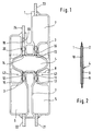
- Fig. 1
- das erfindungsgemäße Bilanzierdisposable in der Draufsicht,
- Fig. 2
- einen Schnitt durch die Bilanzierkammer des Bilanzierdisposables,
- Fig. 3a
- einen Schnitt durch die zwischen den beiden Aufnahmekörpern des Systemeinschubs liegende Bilanzierkammer des Bilanzierdisposables, wobei die untere Kammerhälfte gefüllt und die obere Kammerhälfte entleert ist,
- Fig. 3b
- einen Schnitt durch die zwischen den beiden Aufnahmekörpern des Systemeinschubs liegende Bilanzierkammer des Bilanzierdisposables, wobei die untere Kammerhälfte entleert und die obere Kammerhälfte gefüllt ist,
- Fig. 4
- eine zweite Ausführungsform des Bildanzierdisposables mit einer integrierten Heizfolie, und
- Fig. 5
- den aufgeklappten Systemeinschub der medizinischen Behandlungsvorrichtung mit den beiden Aufnahmekörpern zur Aufnahme des erfindungsgemäßen Bilanzierdisposables.
- Fig. 1
- the balancing disposable according to the invention in plan view,
- Fig. 2
- a section through the balancing chamber of the balancing disposable,
- Fig. 3a
- 3 shows a section through the balancing chamber of the balancing disposable located between the two receiving bodies of the system insert, the lower chamber half being filled and the upper chamber half being emptied,
- Fig. 3b
- 2 shows a section through the balancing chamber of the balancing disposable located between the two receptacles of the system insert, the lower chamber half being emptied and the upper chamber half being filled,
- Fig. 4
- a second embodiment of the image disposable with an integrated heating foil, and
- Fig. 5
- the opened system insert of the medical treatment device with the two receiving bodies for receiving the accounting disposable according to the invention.
Fig. 1 zeigt das Bilanzierdisposable für eine medizinische Behandlungsvorrichtung. Das Bilanzierdisposable weist zwei flexible, im wesentlichen rechteckförmige Kunststoffolien 1, 2 auf, die entlang der mit dem Bezugszeichen 3 versehenen Nahtstellen derart miteinander verschweißt sind, daß zwischen der oberen und unteren Folie 1,2 insgesamt vier Kammern ausgebildet sind. Im Zentrum des Disposables befindet sich eine Bilanzierkammer 4 mit einer ovalen Form. Auf der einen Seite der Bilanzierkammer sind eine erste rechteckförmige Ausgleichskammer 5 und eine zweite rechteckförmige Ausgleichskammer 6 angeordnet, die das gleiche Aufnahmevolumen haben. Auf der anderen Seite der Bilanzierkammer 4 ist eine Pufferkammer 7 angeordnet.1 shows the balancing disposable for a medical treatment device. The balancing disposable has two flexible, essentially rectangular plastic foils 1, 2 which are welded to one another along the seams provided with the
Die Bilanzierkammer 4 weist eine flexible und elastische Wand 8 auf, die die Kammer in eine erste untere und eine zweite obere Kammerhälfte 9, 10 unterteilt, wobei jede Kammerhälfte 9, 10 mit einem Eingang 11, 12 und einem Ausgang 13, 14 versehen ist. Die flexible Wand 8 besteht aus einer in Fig. 1 durch gestrichelte Linien angedeutete rechteckförmige Zwischenfolie, die im Bereich des Bilanziervolumens zwischen die obere und untere Folie 1, 2 eingelegt ist und unter Ausbildung der beiden Kammerhälften 9, 10 mit den äußeren Folien 1, 2, verschweißt ist (Fig. 2).The balancing
Die untere Kammerhälfte 9 ist über einen ersten Einlaßkanal 17 mit der ersten Ausgleichskammer 5 in Fluidverbindung verbunden, während die obere Bilanzierkammerhälfte ist über einen zweiten Einlaßkanal 15 mit der zweiten Ausgleichskammer 6 und über einen schräg gegenüberliegenden zweiten Auslaßkanal 16 mit der Pufferkammer 7 in Fluidverbindung steht. An den Ausgang 14 der ersten Bilanzierkammerhälfte 9 ist ein erster Auslaßkanal 18 angeschlossen. Die Ein- und Auslaßkanäle 15 bis 18 zwischen den Kammern 4 bis 7 werden durch flexible Kunststoffschläuche 19 gebildet, die zwischen die obere und untere Folie 1, 2 eingelegt sind und mit den äußeren Folien verschweißt sind. Die Eingänge bzw. die Ausgänge der Schläuche 19 sind so mit der Zwischenfolie 8 der Bilanzierkammer 4 verschweißt, daß sich ein Eingang und ein Ausgang oberhalb und ein Eingang und ein Ausgang unterhalb der Zwischenfolie 8 befindet und eine direkte Verbindung zwischen der oberen und der unteren Bilanzierkammerhälfte 9, 10 nicht gegeben ist.The
Die eingelegten Kunststoffschläuche 19 verhindern nicht nur ein Kollabieren der Schlauchkanäle bei Unterdruck, sondern schaffen auch in Fig. 1 durch Kreise dargestellte Klemmstellen 20, die sich druckdicht abklemmen lassen. Mit dem Eingang der ersten Ausgleichskammer 5 ist eine erste Zuleitung 21, mit dem Eingang der zweiten Ausgleichskammer 6 ist eine zweite Zuleitung 22, mit dem Ende des ersten Auslaßkanals 18 ist eine erste Auslaßleitung 24 und mit dem Ausgang der Pufferkammer 7 ist eine zweite Auslaßleitung 23 verschweißt. Die Ein- und Auslaßleitungen 21 bis 24 können mit in Fig. 1 nicht dargestellten Anschlußstücken versehen sein. Ferner weist das Bilanzierdisposable seitlich neben der Bilanzierkammer angeordnete Durchbrüche 43 zur Aufnahme von Fixierungsstiften auf. Dabei sind die Kammern jeweils als Beutelanordnungen zu verstehen.The inserted
Das erfindungsgemäße Bilanzierdisposable kann z.B. in einer Blutbehandlungsvorrichtung mit einer volumetrischen Flüssigkeitsbilanzierung Verwendung finden, die ein durch eine semipermeable Membran in eine Blutkammer und eine Filtratkammer unterteiltes Filter aufweist. Eine derartige extrakorporale Blutbehandlungsvorrichtung ist beispielsweise aus DE 41 16 178 C1 bekannt, auf die ausdrücklich Bezug genommen wird. Sofern das Bilanzierdisposable in einer derartigen Blutbehandlungsvorrichtung verwendet wird, bildet die erste Ausgleichskammer 5 die Filtratausgleichskammer und die zweite Ausgleichskammer 6 die Substituatausgleichskammer, während der erste und zweite Einlaßkanal 17, 15 den Filtrat- und Substituateinlaßkanal und der erste und zweite Auslaßkanal 18, 16 den Filtrat- und Substituatauslaßkanal bilden. Das erfindungsgemäße Bilanzierdisposable kann aber auch in vorteilhafter Weise in einer Vorrichtung zur Peritonealdialyse Verwendung finden, mit der zyklisch Peritonealdialysieiflüssigkeit in exakt bilanzierter Weise einem Patienten zugeführt bzw. entnommen werden kann. Hierzu werden die beiden Zuleitungen 21, 22 zu einer gemeinsamen Einlaßleitung zusammengeführt und die beiden Auslaßleitungen 23, 24 werden zu einer gemeinsamen Auslaßleitung zusammengeführt, wobei die Dialysierflüssigkeit über die gemeinsame Einlaßleitung wechselweise in die erste und zweite Bilanzierkammerhälfte 9, 10 geleitet wird und über die gemeinsame Auslaßleitung dem Peritonealraum des Patienten zugeführt wird. Bei einem derartigen Peritonealdialysegerät wird vorteilhafterweise eine Pufferkammer in den ersten und eine Pufferkammer in den zweiten Auslaßkanal geschaltet. Alternativ kann aber auch eine Pufferkammer nach der Zusammenführung in die gemeinsame Auslaßleitung geschaltet werden.The balancing disposable according to the invention can be used, for example, in a blood treatment device with a volumetric liquid balance, which has a filter divided into a blood chamber and a filtrate chamber by a semipermeable membrane. Such an extracorporeal blood treatment device is known for example from
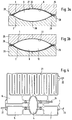
Fig. 2 zeigt einen Schnitt durch die Bilanzierkammer 4 des nicht mit Flüssigkeit gefüllten Bilanzierdisposables. Die Zwischenfolie 8 ist mit ihrem äußeren Rand mit den Rändern der Ober- und Unterfolie 1, 2 verschweißt und in der Bilanzkammer 4 zwischen den äußeren Folien frei beweglich. Da sich wegen der Elastizität der Kunststoffolien ein konstantes Volumen nicht genau einhalten läßt, wird das Bilanziervolumen durch eine feste äußere Form definiert. Das Bilanzierdisposable wird daher in einen Systemeinschub eingesetzt, der Bestandteil der Blutbehandlungvorrichtung ist. Der im einzelnen noch unter Bezugnahme auf Fig. 5 beschriebene Systemeinschub weist zwei Aufnahmekörper 25, 26 mit jeweils einer im Bereich des Bilanziervolumens vorgesehenen Vertiefung 27 auf.2 shows a section through the balancing
Die Fign. 3a und 3b zeigen einen Schnitt durch die zwischen den beiden Aufnahmekörpern 25, 26 des Systemeinschubs liegende Bilanzierkammer 4 des Disposables. Der obere und untere Aufnahmekörper 25, 26 des Systemeinschubs ist mit einem längslaufenden Klemmrand 28, 29 versehen, der die Randbereiche des Bilanzierdisposables fixiert. Wird das Volumen zwischen der Oberfolie 1 und der Zwischenfolie 8 mit Flüssigkeit gefüllt, so wird bei entsprechendem Öffnen und Schließen der Ein- und Ausgänge der Bilanzierkammer 4 durch Umschlagen der Zwischenfolie 8 das andere Volumen zwischen der Zwischenfolie 8 und der Unterfolie 2 infolge der Verdrängung entleert (Fig. 3b). Damit sich die Ober- und Unterfolie 1, 2 des Disposables dicht an die Schalen der Aufnahmekörper 25, 26 anlegen können, sind in den Aufnahmekörpern Entlüftungsöffnungen 30 vorgesehen.The figures 3a and 3b show a section through the balancing
Fig. 4 zeigt eine zweite Ausführungsform des Bilanzierdisposables. Das in Fig. 5 dargestellte Bilanzierdisposable unterscheidet sich von dem unter Bezugnahme auf die Fign. 1 bis 3 beschriebenen Disposables dadurch, daß ein schlangenförmiger Kanal 31 ausgebildet ist, der in die zweite Ausgleichskammer 6 mündet und eine Temperierung der zugeführten Flüssigkeit ermöglicht. Die Erwärmung des Fluids erfolgt durch die Heizfolien hindurch mittels in einem entsprechenden Systemeinschub vorgesehener Heizplatten, die mit der Heizfolie des Disposables in Kontakt gebracht werden. Zur Regelung und Temperaturüberwachung können in Fig. 4 nicht dargestellte Temperatursensoren vorgesehen sein, die auf einfache Weise die Temperatur an den Oberflächen der beiden äußeren Folien 1, 2 messen können. Zweckmäßigerweise wird zumindest ein Regel- und ein Schutzsensor stromab der Heizfolie angeordnet. Zusätzlich kann ein weiterer Temperatursensor am Heizfolieneingang vorteilhaft sein.4 shows a second embodiment of the balancing disposable. The balancing disposable shown in FIG. 5 differs from that with reference to FIGS. 1 to 3 described disposables in that a
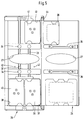
Fig. 5 zeigt den aufgeklappten Systemeinschub der medizinischen Behandlungsvorrichtung in der Draufsicht, in den das Bilanzierdisposable passend eingelegt wird. Der obere und untere in seinen äußeren Abmessungen dem Disposable entsprechende Aufnahmekörper 25, 26 des Systemeinschubs sind mit einem Scharnier 44 an ihren Längsseiten miteinander verbunden. Die Vertiefungen 27 zur Aufnahme der Bilanzierkammerhälften 9, 10 sind in Zentrum der beiden Aufnahmekörper 25, 26 angeordnet. Die Fixierung des Disposables erfolgt mit den Führungsstiften 42, die in die entsprechenden Durchbrüche 43 des Disposables greifen. Zu beiden Seiten der Vertiefungen 27 sind in dem unteren Aufnahmekörper 26 jeweils zwei parallele Führungskanäle 32, 33 zur Aufnahme der Ein- und Auslaßkanäle 15-18 vorgesehen. Ferner sind innerhalb der Führungskanäle 32, 33 vier Stößel 34 angeordnet, die mit den Klemmkanten 35 zusammenwirken, die sich auf der Höhe der Stößel 34 in dem oberen Aufnahmekörper 25 befinden. Mit den elektromagnetisch betätigbaren Stößeln 34 können die Klemmstellen 20 der Kanäle des Disposables druckdicht abgeklemmt werden. Seitlich neben den Stößeln 34 bzw. den Klemmkanten 35 sind in dem unteren und oberen Aufnahmekörper 25, 26 Einsatzstücke 36, 37, 38 zur Aufnahme der ersten- bzw. der zweiten Ausgleichskammer 5, 6 sowie der Pufferkammer 7 vorgesehen. Am Boden der Einsatzstücke 37, 38 für die Ausgleichskammern sind die federnd vorgespannten Druckplatten 39, 40 der in dem Systemeinschub befindlichen Kompressionseinrichtungen angeordnet, mit denen die Ausgleichskammern 5, 6 des Disposables mit Druck beaufschlagt werden. Die Funktion der Klemmeinrichtungen und der Kompressionseinrichtungen ist in DE 41 16 178 C1 beschrieben, auf die ausdrücklich Bezug genommen wird. Am Boden des Einsatzstücks 40 für die Pufferkammer 7 ist eine weitere Druckplatte 41 vorgesehen. Diese kann mit der Druckplatte 39 der ersten Ausgleichskammer derart mechanisch gekoppelt sein, daß sie eine gegenläufige Bewegung ausübt.FIG. 5 shows a top view of the opened system insert of the medical treatment device, into which the balancing disposable is inserted appropriately. The upper and
Claims (9)
einer durch eine flexible Wand (8) in eine erste und eine zweite Kammerhälfte (9, 10) unterteilten Bilanzierkammer (4), wobei die flexible Wand (8) der Bilanzierkammer (4) durch eine Zwischenfolie gebildet wird, die zwischen der ersten und zweiten Folie (1, 2) im Bereich des Bilanziervolumens eingelegt und mit den äußeren Folien (1, 2) unter Bildung der beiden Kammerhälften (9, 10) derart verbunden ist, daß die erste Kammerhälfte (9) von der zweiten Kammerhälfte (10) druckdicht getrennt ist,
einer über einen druckdicht abklemmbaren ersten Einlaßkanal (17) mit der ersten Kammerhälfte (9) der Bilanzierkammer (4) in Fluidverbindung stehenden ersten Ausgleichskammer (5),
einer über einen druckdicht abklemmbaren zweiten Einlaßkanal (15) mit der zweiten Kammerhälfte (10) der Bilanzierkammer (4) in Fluidverbindung stehenden zweiten Ausgleichskammer (6) und
eines mit der ersten Kammerhälfte (9) der Bilanzierkammer (4) in Fluidverbindung stehenden druckdicht abklemmbaren ersten Auslaßkanals (18) und eines mit der zweiten Kammerhälfte (10) der Bilanzierkammer (4) in Fluidverbindung stehenden druckdicht abklemmbaren zweiten Auslaßkanals (16).Balancing disposable for balancing liquids for a medical treatment device with two superimposed plastic films (1, 2), which are connected to each other pressure-tight to form
a balancing chamber (4) divided by a flexible wall (8) into a first and a second chamber half (9, 10), the flexible wall (8) of the balancing chamber (4) being formed by an intermediate film which is between the first and second Foil (1, 2) is inserted in the area of the balancing volume and is connected to the outer foils (1, 2) to form the two chamber halves (9, 10) in such a way that the first chamber half (9) is pressure-tight from the second chamber half (10) is separated
a first compensation chamber (5), which can be clamped off in a pressure-tight manner, is in fluid communication with the first chamber half (9) of the balancing chamber (4),
a second compensation chamber (6), which can be clamped off in a pressure-tight manner, is in fluid communication with the second chamber half (10) of the balancing chamber (4) and
one with the first chamber half (9) of the balancing chamber (4) in fluid connection, can be disconnected in a pressure-tight manner, and a first outlet channel (18), which is in fluid communication with the second chamber half (10) of the balancing chamber (4), can be disconnected in pressure-tight manner.
Applications Claiming Priority (2)
| Application Number | Priority Date | Filing Date | Title |
|---|---|---|---|
| DE19546028A DE19546028C2 (en) | 1995-12-09 | 1995-12-09 | Balancing disposable for balancing liquids for a medical treatment device and a medical treatment device with a system insert for receiving such a balancing disposable |
| DE19546028 | 1995-12-09 |
Publications (2)
| Publication Number | Publication Date |
|---|---|
| EP0778033A2 true EP0778033A2 (en) | 1997-06-11 |
| EP0778033A3 EP0778033A3 (en) | 1997-11-05 |
Family
ID=7779688
Family Applications (1)
| Application Number | Title | Priority Date | Filing Date |
|---|---|---|---|
| EP96119251A Withdrawn EP0778033A3 (en) | 1995-12-09 | 1996-11-30 | Blood treatment device with balanced flow |
Country Status (5)
| Country | Link |
|---|---|
| US (1) | US5836908A (en) |
| EP (1) | EP0778033A3 (en) |
| JP (1) | JPH09276398A (en) |
| AU (1) | AU710005B2 (en) |
| DE (1) | DE19546028C2 (en) |
Cited By (16)
| Publication number | Priority date | Publication date | Assignee | Title |
|---|---|---|---|---|
| US5986116A (en) * | 1996-10-30 | 1999-11-16 | Rinoru Oil Mills Co., Ltd. | Method for producing conjugated linoleic acid |
| EP0956876A1 (en) * | 1998-04-01 | 1999-11-17 | Fresenius Medical Care Deutschland GmbH | Cassette for the delivery of fluids, especially dialysis fluids |
| US7867214B2 (en) | 2002-07-19 | 2011-01-11 | Baxter International Inc. | Systems and methods for performing peritoneal dialysis |
| US7922686B2 (en) | 2002-07-19 | 2011-04-12 | Baxter International Inc. | Systems and methods for performing peritoneal dialysis |
| US7922911B2 (en) | 2002-07-19 | 2011-04-12 | Baxter International Inc. | Systems and methods for peritoneal dialysis |
| WO2011091975A1 (en) * | 2010-01-26 | 2011-08-04 | Fresenius Medical Care Deutschland Gmbh | Dialysis machine |
| EP2260888A3 (en) * | 2002-05-24 | 2012-05-09 | Baxter International Inc. | Fluid pumping, valve and heating systems, methods and apparatuses for an automated dialysis machine |
| US8540886B2 (en) | 2008-08-18 | 2013-09-24 | Fresenius Medical Care Deutschland Gmbh | Dialysis cassettes and related systems and methods |
| EP1511524B1 (en) * | 2002-05-24 | 2015-02-25 | Baxter International Inc. | Automated dialysis system |
| US10232103B1 (en) | 2001-11-13 | 2019-03-19 | Baxter International Inc. | System, method, and composition for removing uremic toxins in dialysis processes |
| US10603424B2 (en) | 2011-03-23 | 2020-03-31 | Nxstage Medical, Inc. | Peritoneal dialysis systems, devices, and methods |
| US10646634B2 (en) | 2008-07-09 | 2020-05-12 | Baxter International Inc. | Dialysis system and disposable set |
| US11207454B2 (en) | 2018-02-28 | 2021-12-28 | Nxstage Medical, Inc. | Fluid preparation and treatment devices methods and systems |
| US11400193B2 (en) | 2008-08-28 | 2022-08-02 | Baxter International Inc. | In-line sensors for dialysis applications |
| US11495334B2 (en) | 2015-06-25 | 2022-11-08 | Gambro Lundia Ab | Medical device system and method having a distributed database |
| US11516183B2 (en) | 2016-12-21 | 2022-11-29 | Gambro Lundia Ab | Medical device system including information technology infrastructure having secure cluster domain supporting external domain |
Families Citing this family (63)
| Publication number | Priority date | Publication date | Assignee | Title |
|---|---|---|---|---|
| AU3273201A (en) * | 1997-02-14 | 2001-06-04 | Nxstage Medical, Inc. | Fluid processing systems and methods using extracorporeal fluid flow panels oriented within a cartridge |
| US6638477B1 (en) | 1997-02-14 | 2003-10-28 | Nxstage Medical, Inc. | Fluid replacement systems and methods for use in hemofiltration |
| US6638478B1 (en) * | 1997-02-14 | 2003-10-28 | Nxstage Medical, Inc. | Synchronized volumetric fluid balancing systems and methods |
| US6554789B1 (en) | 1997-02-14 | 2003-04-29 | Nxstage Medical, Inc. | Layered fluid circuit assemblies and methods for making them |
| US20010016699A1 (en) | 1997-02-14 | 2001-08-23 | Jeffrey H. Burbank | Hemofiltration system |
| US6830553B1 (en) | 1997-02-14 | 2004-12-14 | Nxstage Medical, Inc. | Blood treatment systems and methods that maintain sterile extracorporeal processing conditions |
| US6589482B1 (en) | 1997-02-14 | 2003-07-08 | Nxstage Medical, Inc. | Extracorporeal circuits for performing hemofiltration employing pressure sensing without an air interface |
| US6595943B1 (en) | 1997-02-14 | 2003-07-22 | Nxstage Medical, Inc. | Systems and methods for controlling blood flow and waste fluid removal during hemofiltration |
| US6673314B1 (en) | 1997-02-14 | 2004-01-06 | Nxstage Medical, Inc. | Interactive systems and methods for supporting hemofiltration therapies |
| US6852090B2 (en) * | 1997-02-14 | 2005-02-08 | Nxstage Medical, Inc. | Fluid processing systems and methods using extracorporeal fluid flow panels oriented within a cartridge |
| US7780619B2 (en) | 1999-11-29 | 2010-08-24 | Nxstage Medical, Inc. | Blood treatment apparatus |
| US6497676B1 (en) | 2000-02-10 | 2002-12-24 | Baxter International | Method and apparatus for monitoring and controlling peritoneal dialysis therapy |
| SE0000866L (en) * | 2000-03-16 | 2001-09-17 | Peter Unger Med P U Med Konsul | Method and apparatus for the treatment of biological material |
| JP4643815B2 (en) * | 2000-10-04 | 2011-03-02 | テルモ株式会社 | Peritoneal dialysis machine |
| DE10124951C1 (en) | 2001-05-21 | 2002-12-05 | Plasmaselect Ag | Method and device for balancing liquids |
| US20050010158A1 (en) * | 2001-05-24 | 2005-01-13 | Brugger James M. | Drop-in blood treatment cartridge with filter |
| US6769231B2 (en) | 2001-07-19 | 2004-08-03 | Baxter International, Inc. | Apparatus, method and flexible bag for use in manufacturing |
| US7153285B2 (en) * | 2002-01-17 | 2006-12-26 | Baxter International Inc. | Medical fluid heater using radiant energy |
| US20030217957A1 (en) * | 2002-05-24 | 2003-11-27 | Bowman Joseph H. | Heat seal interface for a disposable medical fluid unit |
| US7175606B2 (en) | 2002-05-24 | 2007-02-13 | Baxter International Inc. | Disposable medical fluid unit having rigid frame |
| US7153286B2 (en) | 2002-05-24 | 2006-12-26 | Baxter International Inc. | Automated dialysis system |
| US6764761B2 (en) | 2002-05-24 | 2004-07-20 | Baxter International Inc. | Membrane material for automated dialysis system |
| US7115228B2 (en) * | 2002-05-24 | 2006-10-03 | Baxter International Inc. | One-piece tip protector and organizer |
| US7238164B2 (en) | 2002-07-19 | 2007-07-03 | Baxter International Inc. | Systems, methods and apparatuses for pumping cassette-based therapies |
| US7112273B2 (en) * | 2002-09-27 | 2006-09-26 | Nxstage Medical, Inc. | Volumetric fluid balance control for extracorporeal blood treatment |
| WO2004066121A2 (en) * | 2003-01-15 | 2004-08-05 | Nxstage Medical Inc. | Waste balancing for extracorporeal blood treatment systems |
| US8235931B2 (en) | 2003-01-15 | 2012-08-07 | Nxstage Medical, Inc. | Waste balancing for extracorporeal blood treatment systems |
| MX351817B (en) | 2003-10-28 | 2017-10-30 | Baxter Healthcare Sa | Improved priming, integrity and head height methods and apparatuses for medical fluid systems. |
| US8803044B2 (en) | 2003-11-05 | 2014-08-12 | Baxter International Inc. | Dialysis fluid heating systems |
| US8038639B2 (en) * | 2004-11-04 | 2011-10-18 | Baxter International Inc. | Medical fluid system with flexible sheeting disposable unit |
| US8029454B2 (en) | 2003-11-05 | 2011-10-04 | Baxter International Inc. | High convection home hemodialysis/hemofiltration and sorbent system |
| US7744553B2 (en) | 2003-12-16 | 2010-06-29 | Baxter International Inc. | Medical fluid therapy flow control systems and methods |
| CA2970214C (en) | 2006-04-14 | 2021-08-17 | Deka Products Limited Partnership | System for pumping a biological fluid |
| US10537671B2 (en) | 2006-04-14 | 2020-01-21 | Deka Products Limited Partnership | Automated control mechanisms in a hemodialysis apparatus |
| US7731689B2 (en) | 2007-02-15 | 2010-06-08 | Baxter International Inc. | Dialysis system having inductive heating |
| US8042563B2 (en) | 2007-02-27 | 2011-10-25 | Deka Products Limited Partnership | Cassette system integrated apparatus |
| US8409441B2 (en) | 2007-02-27 | 2013-04-02 | Deka Products Limited Partnership | Blood treatment systems and methods |
| US9517295B2 (en) | 2007-02-27 | 2016-12-13 | Deka Products Limited Partnership | Blood treatment systems and methods |
| US8357298B2 (en) * | 2007-02-27 | 2013-01-22 | Deka Products Limited Partnership | Hemodialysis systems and methods |
| US8888470B2 (en) | 2007-02-27 | 2014-11-18 | Deka Products Limited Partnership | Pumping cassette |
| KR20230165373A (en) | 2007-02-27 | 2023-12-05 | 데카 프로덕츠 리미티드 파트너쉽 | Hemodialysis system |
| US8057423B2 (en) | 2007-07-05 | 2011-11-15 | Baxter International Inc. | Dialysis system having disposable cassette |
| US7901376B2 (en) * | 2007-07-05 | 2011-03-08 | Baxter International Inc. | Dialysis cassette having multiple outlet valve |
| US8078333B2 (en) | 2007-07-05 | 2011-12-13 | Baxter International Inc. | Dialysis fluid heating algorithms |
| US7809254B2 (en) * | 2007-07-05 | 2010-10-05 | Baxter International Inc. | Dialysis fluid heating using pressure and vacuum |
| US8114276B2 (en) | 2007-10-24 | 2012-02-14 | Baxter International Inc. | Personal hemodialysis system |
| US9415150B2 (en) * | 2007-11-09 | 2016-08-16 | Baxter Healthcare S.A. | Balanced flow dialysis machine |
| US8062513B2 (en) | 2008-07-09 | 2011-11-22 | Baxter International Inc. | Dialysis system and machine having therapy prescription recall |
| US9514283B2 (en) | 2008-07-09 | 2016-12-06 | Baxter International Inc. | Dialysis system having inventory management including online dextrose mixing |
| EP2482868B1 (en) | 2009-09-29 | 2014-09-03 | Fresenius Medical Care Deutschland GmbH | Device for dialysis treatment and method for balancing fresh and used dialysis liquid |
| DE102009048561B4 (en) | 2009-10-07 | 2017-01-26 | Fresenius Medical Care Deutschland Gmbh | Apparatus for dialysis treatment |
| US8821135B2 (en) | 2010-08-25 | 2014-09-02 | Emory University | Devices and systems for medical fluid treatment |
| DE102011016870B4 (en) | 2011-04-13 | 2013-06-20 | Fresenius Medical Care Deutschland Gmbh | Device for conveying a fluid to a filter unit of a medical treatment device and method for measuring the pressure in the fluid flow system of such a device |
| DE102011016869A1 (en) | 2011-04-13 | 2012-10-18 | Fresenius Medical Care Deutschland Gmbh | Apparatus and method for conveying a liquid to a filter unit of a medical treatment device |
| SG10201604142SA (en) | 2011-05-24 | 2016-07-28 | Deka Products Lp | Hemodialysis System |
| EP3539586B1 (en) | 2014-10-10 | 2022-08-24 | NxStage Medical Inc. | Flow balancing methods |
| DE102015015636A1 (en) * | 2015-12-02 | 2017-06-08 | Fresenius Medical Deutschland Gmbh | Method for testing the rigidity of a disposable |
| JP7086926B2 (en) | 2016-07-18 | 2022-06-20 | ネクステージ メディカル インコーポレイテッド | Flow balancing equipment, methods, and systems |
| EP3554575A4 (en) | 2016-12-14 | 2020-08-12 | NxStage Medical, Inc. | Treatment fluid multi-stream blood warmer |
| WO2018145035A1 (en) | 2017-02-03 | 2018-08-09 | Nxstage Medical, Inc. | Multiple mode treatment devices methods and systems |
| US11179516B2 (en) | 2017-06-22 | 2021-11-23 | Baxter International Inc. | Systems and methods for incorporating patient pressure into medical fluid delivery |
| WO2019191645A1 (en) | 2018-03-30 | 2019-10-03 | Deka Products Limited Partnership | Liquid pumping cassettes and associated pressure distribution manifold and related methods |
| US11911548B2 (en) | 2020-12-10 | 2024-02-27 | Baxter International Inc. | Peritoneal dialysis system including manifold assembly and peristaltic pump |
Citations (2)
| Publication number | Priority date | Publication date | Assignee | Title |
|---|---|---|---|---|
| DE3428828C2 (en) | 1984-08-04 | 1989-04-27 | Karl-Theo 6652 Bexbach De Braun | |
| DE4116178C1 (en) | 1991-05-17 | 1992-11-12 | Fresenius Ag, 6380 Bad Homburg, De |
Family Cites Families (5)
| Publication number | Priority date | Publication date | Assignee | Title |
|---|---|---|---|---|
| USRE26006E (en) * | 1959-12-23 | 1966-04-26 | Transfusion set | |
| US3709222A (en) * | 1970-12-28 | 1973-01-09 | Sarns Inc | Method and apparatus for automatic peritoneal dialysis |
| US4209391A (en) * | 1978-11-06 | 1980-06-24 | Cordis Dow Corp. | Apparatus and method for automatically controlling hemodialysis at a pre-selected ultrafiltration rate |
| US4366061A (en) * | 1980-01-23 | 1982-12-28 | Cordis Dow Corp. | Automated diaphragm apparatus and method for controlling negative pressure hemodialysis treatment |
| US4976162A (en) * | 1987-09-03 | 1990-12-11 | Kamen Dean L | Enhanced pressure measurement flow control system |
-
1995
- 1995-12-09 DE DE19546028A patent/DE19546028C2/en not_active Expired - Lifetime
-
1996
- 1996-11-30 EP EP96119251A patent/EP0778033A3/en not_active Withdrawn
- 1996-12-05 AU AU74198/96A patent/AU710005B2/en not_active Ceased
- 1996-12-06 JP JP8342628A patent/JPH09276398A/en active Pending
- 1996-12-09 US US08/762,084 patent/US5836908A/en not_active Expired - Lifetime
Patent Citations (2)
| Publication number | Priority date | Publication date | Assignee | Title |
|---|---|---|---|---|
| DE3428828C2 (en) | 1984-08-04 | 1989-04-27 | Karl-Theo 6652 Bexbach De Braun | |
| DE4116178C1 (en) | 1991-05-17 | 1992-11-12 | Fresenius Ag, 6380 Bad Homburg, De |
Cited By (40)
| Publication number | Priority date | Publication date | Assignee | Title |
|---|---|---|---|---|
| US5986116A (en) * | 1996-10-30 | 1999-11-16 | Rinoru Oil Mills Co., Ltd. | Method for producing conjugated linoleic acid |
| EP0956876A1 (en) * | 1998-04-01 | 1999-11-17 | Fresenius Medical Care Deutschland GmbH | Cassette for the delivery of fluids, especially dialysis fluids |
| US10980931B2 (en) | 2001-11-13 | 2021-04-20 | Baxter International Inc. | System, method, and composition for removing uremic toxins in dialysis processes |
| US10232103B1 (en) | 2001-11-13 | 2019-03-19 | Baxter International Inc. | System, method, and composition for removing uremic toxins in dialysis processes |
| EP2260888A3 (en) * | 2002-05-24 | 2012-05-09 | Baxter International Inc. | Fluid pumping, valve and heating systems, methods and apparatuses for an automated dialysis machine |
| EP1511524B1 (en) * | 2002-05-24 | 2015-02-25 | Baxter International Inc. | Automated dialysis system |
| US9764074B1 (en) | 2002-07-19 | 2017-09-19 | Baxter International Inc. | Systems and methods for performing dialysis |
| US9814820B2 (en) | 2002-07-19 | 2017-11-14 | Baxter International Inc. | Weight-controlled sorbent system for hemodialysis |
| US7867214B2 (en) | 2002-07-19 | 2011-01-11 | Baxter International Inc. | Systems and methods for performing peritoneal dialysis |
| US8597227B2 (en) | 2002-07-19 | 2013-12-03 | Baxter International Inc. | Weight/sensor-controlled sorbent system for hemodialysis |
| US11235094B2 (en) | 2002-07-19 | 2022-02-01 | Baxter International Inc. | System for peritoneal dialysis |
| US8815095B2 (en) | 2002-07-19 | 2014-08-26 | Baxter International Inc. | Peritoneal dialysis systems and methods that regenerate dialysate |
| US7922911B2 (en) | 2002-07-19 | 2011-04-12 | Baxter International Inc. | Systems and methods for peritoneal dialysis |
| US8998839B2 (en) | 2002-07-19 | 2015-04-07 | Baxter International Inc. | Systems and methods for performing peritoneal dialysis |
| US10363352B2 (en) | 2002-07-19 | 2019-07-30 | Baxter International Inc. | Disposable set and system for dialysis |
| US7922686B2 (en) | 2002-07-19 | 2011-04-12 | Baxter International Inc. | Systems and methods for performing peritoneal dialysis |
| US8357113B2 (en) | 2002-07-19 | 2013-01-22 | Baxter International Inc. | Systems and methods for performing peritoneal dialysis |
| US10179200B2 (en) | 2002-07-19 | 2019-01-15 | Baxter International Inc. | Disposable cassette and system for dialysis |
| US10646634B2 (en) | 2008-07-09 | 2020-05-12 | Baxter International Inc. | Dialysis system and disposable set |
| US9302040B2 (en) | 2008-08-18 | 2016-04-05 | Fresenius Medical Care Deutschland Gmbh | Dialysis cassettes and related systems and methods |
| US8540886B2 (en) | 2008-08-18 | 2013-09-24 | Fresenius Medical Care Deutschland Gmbh | Dialysis cassettes and related systems and methods |
| US11400193B2 (en) | 2008-08-28 | 2022-08-02 | Baxter International Inc. | In-line sensors for dialysis applications |
| US8702985B2 (en) | 2010-01-26 | 2014-04-22 | Fresenius Medical Care Deutschland Gmbh | Dialysis machine |
| WO2011091975A1 (en) * | 2010-01-26 | 2011-08-04 | Fresenius Medical Care Deutschland Gmbh | Dialysis machine |
| US10688234B2 (en) | 2011-03-23 | 2020-06-23 | Nxstage Medical, Inc. | Peritoneal dialysis systems, devices, and methods |
| US10688235B2 (en) | 2011-03-23 | 2020-06-23 | Nxstage Medical, Inc. | Peritoneal dialysis systems, devices, and methods |
| US10898630B2 (en) | 2011-03-23 | 2021-01-26 | Nxstage Medical, Inc. | Peritoneal dialysis systems, devices, and methods |
| US10610630B2 (en) | 2011-03-23 | 2020-04-07 | Nxstage Medical, Inc. | Peritoneal dialysis systems, devices, and methods |
| US11135348B2 (en) | 2011-03-23 | 2021-10-05 | Nxstage Medical, Inc. | Peritoneal dialysis systems, devices, and methods |
| US11717601B2 (en) | 2011-03-23 | 2023-08-08 | Nxstage Medical, Inc. | Dialysis systems, devices, and methods |
| US11224684B2 (en) | 2011-03-23 | 2022-01-18 | Nxstage Medical, Inc. | Peritoneal dialysis systems, devices, and methods |
| US10603424B2 (en) | 2011-03-23 | 2020-03-31 | Nxstage Medical, Inc. | Peritoneal dialysis systems, devices, and methods |
| US11690941B2 (en) | 2011-03-23 | 2023-07-04 | Nxstage Medical, Inc. | Peritoneal dialysis systems, devices, and methods |
| US11433169B2 (en) | 2011-03-23 | 2022-09-06 | Nxstage Medical, Inc. | Dialysis systems, devices, and methods |
| US11433170B2 (en) | 2011-03-23 | 2022-09-06 | Nxstage Medical, Inc. | Dialysis systems, devices, and methods |
| US11495334B2 (en) | 2015-06-25 | 2022-11-08 | Gambro Lundia Ab | Medical device system and method having a distributed database |
| US11516183B2 (en) | 2016-12-21 | 2022-11-29 | Gambro Lundia Ab | Medical device system including information technology infrastructure having secure cluster domain supporting external domain |
| US11364328B2 (en) | 2018-02-28 | 2022-06-21 | Nxstage Medical, Inc. | Fluid preparation and treatment devices methods and systems |
| US11207454B2 (en) | 2018-02-28 | 2021-12-28 | Nxstage Medical, Inc. | Fluid preparation and treatment devices methods and systems |
| US11872337B2 (en) | 2018-02-28 | 2024-01-16 | Nxstage Medical, Inc. | Fluid preparation and treatment devices methods and systems |
Also Published As
| Publication number | Publication date |
|---|---|
| AU710005B2 (en) | 1999-09-09 |
| DE19546028C2 (en) | 2000-04-27 |
| DE19546028A1 (en) | 1997-06-12 |
| AU7419896A (en) | 1997-06-12 |
| US5836908A (en) | 1998-11-17 |
| EP0778033A3 (en) | 1997-11-05 |
| JPH09276398A (en) | 1997-10-28 |
Similar Documents
| Publication | Publication Date | Title |
|---|---|---|
| DE19546028C2 (en) | Balancing disposable for balancing liquids for a medical treatment device and a medical treatment device with a system insert for receiving such a balancing disposable | |
| DE19546027C1 (en) | Appts. removing toxic substances from blood by dialysis or related techniques | |
| EP0867195B1 (en) | Device for the ultrafiltration in a hemodialysis operation | |
| DE60030885T2 (en) | FILTER CARTRIDGE FOR STERILE LIQUID AND METHOD FOR THE USE THEREOF | |
| DE3634763A1 (en) | DEVICE AND METHOD FOR CLEANING BLOOD | |
| EP0191071B1 (en) | Device for pumping liquids which are highly sensitive to mechanical strains | |
| DE10042324C1 (en) | Blood dialysis device has feed line provided with 2 parallel branches for single needle and dual needle operating modes | |
| EP1235601B1 (en) | Disposable element for a medical treatment device using a liquid | |
| EP0956876B1 (en) | Cassette for the delivery of fluids, especially dialysis fluids | |
| DE10224750A1 (en) | Device for the treatment of a medical fluid | |
| DE3522489C2 (en) | ||
| DE102005001779A1 (en) | Disposable set for extra-corporal blood treatment using either single- or dual-needle operation, includes air separator connecting to expansion unit to increase its volume | |
| DE2824898A1 (en) | IMPROVED HOLLOW FIBER ARTISTS AND METHODS OF MAKING THEM | |
| DE2806237C2 (en) | Device for removing urinary substances from human blood | |
| DE19607162A1 (en) | Dialyzer | |
| DE102006061184A1 (en) | Method of priming a blood tubing set | |
| DE19830928C1 (en) | Kidney dialysis balance has two chambers each sub-divided by flexible membrane | |
| WO2006087103A1 (en) | Device for the removal of substances form liquids in particular blood | |
| DE19962315C2 (en) | Peritoneal dialysis device | |
| DE19534502C2 (en) | Medical facility | |
| DE1566641A1 (en) | Dialyzer, especially for artificial kidneys | |
| EP0513672B1 (en) | Blood treatment device with volume balanced flow | |
| DE19825568B4 (en) | Use of a film bag for lining a container for providing dialysis fluid and a dialysis device with a receiving unit for receiving the film bag | |
| DE102020133686A1 (en) | Connector for dialyzer port, dialyzer, procedure and blood treatment device | |
| WO2020188040A1 (en) | Extracorporeal blood treatment machine comprising a poka-yoke for a pressure sensor |
Legal Events
| Date | Code | Title | Description |
|---|---|---|---|
| PUAI | Public reference made under article 153(3) epc to a published international application that has entered the european phase |
Free format text: ORIGINAL CODE: 0009012 |
|
| AK | Designated contracting states |
Kind code of ref document: A2 Designated state(s): DE ES FR GB IT |
|
| RAP1 | Party data changed (applicant data changed or rights of an application transferred) |
Owner name: FRESENIUS MEDICAL CARE DEUTSCHLAND GMBH |
|
| PUAL | Search report despatched |
Free format text: ORIGINAL CODE: 0009013 |
|
| AK | Designated contracting states |
Kind code of ref document: A3 Designated state(s): DE ES FR GB IT |
|
| 17P | Request for examination filed |
Effective date: 19980313 |
|
| RAP1 | Party data changed (applicant data changed or rights of an application transferred) |
Owner name: FRESENIUS MEDICAL CARE DEUTSCHLAND GMBH |
|
| 17Q | First examination report despatched |
Effective date: 20020524 |
|
| STAA | Information on the status of an ep patent application or granted ep patent |
Free format text: STATUS: THE APPLICATION IS DEEMED TO BE WITHDRAWN |
|
| 18D | Application deemed to be withdrawn |
Effective date: 20021005 |