EP0885618A1 - Exchanger and method for manufacturing the same - Google Patents
Exchanger and method for manufacturing the same Download PDFInfo
- Publication number
- EP0885618A1 EP0885618A1 EP98109192A EP98109192A EP0885618A1 EP 0885618 A1 EP0885618 A1 EP 0885618A1 EP 98109192 A EP98109192 A EP 98109192A EP 98109192 A EP98109192 A EP 98109192A EP 0885618 A1 EP0885618 A1 EP 0885618A1
- Authority
- EP
- European Patent Office
- Prior art keywords
- blood
- manifold
- casing
- exchanger
- inlet
- Prior art date
- Legal status (The legal status is an assumption and is not a legal conclusion. Google has not performed a legal analysis and makes no representation as to the accuracy of the status listed.)
- Granted
Links
- 238000004519 manufacturing process Methods 0.000 title claims description 11
- 238000000034 method Methods 0.000 title description 10
- 239000008280 blood Substances 0.000 claims abstract description 95
- 210000004369 blood Anatomy 0.000 claims abstract description 95
- 239000000463 material Substances 0.000 claims abstract description 54
- 239000012528 membrane Substances 0.000 claims abstract description 49
- 239000012530 fluid Substances 0.000 claims abstract description 17
- 238000002844 melting Methods 0.000 claims description 5
- 230000008018 melting Effects 0.000 claims description 5
- 229920003023 plastic Polymers 0.000 claims description 3
- 239000004033 plastic Substances 0.000 claims description 3
- 229910001220 stainless steel Inorganic materials 0.000 claims description 3
- 239000010935 stainless steel Substances 0.000 claims description 3
- 239000002184 metal Substances 0.000 claims 2
- 239000013529 heat transfer fluid Substances 0.000 claims 1
- QVGXLLKOCUKJST-UHFFFAOYSA-N atomic oxygen Chemical compound [O] QVGXLLKOCUKJST-UHFFFAOYSA-N 0.000 description 15
- 229910052760 oxygen Inorganic materials 0.000 description 15
- 239000001301 oxygen Substances 0.000 description 15
- 230000017531 blood circulation Effects 0.000 description 9
- 230000009977 dual effect Effects 0.000 description 9
- CURLTUGMZLYLDI-UHFFFAOYSA-N Carbon dioxide Chemical compound O=C=O CURLTUGMZLYLDI-UHFFFAOYSA-N 0.000 description 8
- 229920002803 thermoplastic polyurethane Polymers 0.000 description 7
- 238000003466 welding Methods 0.000 description 6
- 239000004743 Polypropylene Substances 0.000 description 4
- 229910002092 carbon dioxide Inorganic materials 0.000 description 4
- 239000001569 carbon dioxide Substances 0.000 description 4
- 238000007872 degassing Methods 0.000 description 4
- 210000004072 lung Anatomy 0.000 description 4
- 238000006213 oxygenation reaction Methods 0.000 description 4
- -1 polypropylene Polymers 0.000 description 4
- 229920001155 polypropylene Polymers 0.000 description 4
- 239000011347 resin Substances 0.000 description 4
- 229920005989 resin Polymers 0.000 description 4
- 230000001706 oxygenating effect Effects 0.000 description 3
- 238000012546 transfer Methods 0.000 description 3
- JOYRKODLDBILNP-UHFFFAOYSA-N Ethyl urethane Chemical compound CCOC(N)=O JOYRKODLDBILNP-UHFFFAOYSA-N 0.000 description 2
- 238000001816 cooling Methods 0.000 description 2
- 238000005538 encapsulation Methods 0.000 description 2
- 239000007789 gas Substances 0.000 description 2
- 239000007788 liquid Substances 0.000 description 2
- 239000011148 porous material Substances 0.000 description 2
- 239000000523 sample Substances 0.000 description 2
- 238000007789 sealing Methods 0.000 description 2
- 238000001356 surgical procedure Methods 0.000 description 2
- 239000004820 Pressure-sensitive adhesive Substances 0.000 description 1
- 238000007675 cardiac surgery Methods 0.000 description 1
- 230000005792 cardiovascular activity Effects 0.000 description 1
- 238000013130 cardiovascular surgery Methods 0.000 description 1
- 230000005465 channeling Effects 0.000 description 1
- 238000010276 construction Methods 0.000 description 1
- 238000011109 contamination Methods 0.000 description 1
- 238000010586 diagram Methods 0.000 description 1
- 239000011888 foil Substances 0.000 description 1
- 238000010438 heat treatment Methods 0.000 description 1
- 238000002347 injection Methods 0.000 description 1
- 239000007924 injection Substances 0.000 description 1
- 238000005259 measurement Methods 0.000 description 1
- 230000037361 pathway Effects 0.000 description 1
- 238000012545 processing Methods 0.000 description 1
- 239000000565 sealant Substances 0.000 description 1
- 125000006850 spacer group Chemical group 0.000 description 1
- 238000012360 testing method Methods 0.000 description 1
- 230000001225 therapeutic effect Effects 0.000 description 1
- 239000004591 urethane sealant Substances 0.000 description 1
- 239000011800 void material Substances 0.000 description 1
Images


Classifications
-
- B—PERFORMING OPERATIONS; TRANSPORTING
- B01—PHYSICAL OR CHEMICAL PROCESSES OR APPARATUS IN GENERAL
- B01D—SEPARATION
- B01D63/00—Apparatus in general for separation processes using semi-permeable membranes
- B01D63/02—Hollow fibre modules
- B01D63/026—Wafer type modules or flat-surface type modules
-
- A—HUMAN NECESSITIES
- A61—MEDICAL OR VETERINARY SCIENCE; HYGIENE
- A61M—DEVICES FOR INTRODUCING MEDIA INTO, OR ONTO, THE BODY; DEVICES FOR TRANSDUCING BODY MEDIA OR FOR TAKING MEDIA FROM THE BODY; DEVICES FOR PRODUCING OR ENDING SLEEP OR STUPOR
- A61M1/00—Suction or pumping devices for medical purposes; Devices for carrying-off, for treatment of, or for carrying-over, body-liquids; Drainage systems
- A61M1/14—Dialysis systems; Artificial kidneys; Blood oxygenators ; Reciprocating systems for treatment of body fluids, e.g. single needle systems for hemofiltration or pheresis
- A61M1/16—Dialysis systems; Artificial kidneys; Blood oxygenators ; Reciprocating systems for treatment of body fluids, e.g. single needle systems for hemofiltration or pheresis with membranes
- A61M1/1621—Constructional aspects thereof
- A61M1/1629—Constructional aspects thereof with integral heat exchanger
-
- A—HUMAN NECESSITIES
- A61—MEDICAL OR VETERINARY SCIENCE; HYGIENE
- A61M—DEVICES FOR INTRODUCING MEDIA INTO, OR ONTO, THE BODY; DEVICES FOR TRANSDUCING BODY MEDIA OR FOR TAKING MEDIA FROM THE BODY; DEVICES FOR PRODUCING OR ENDING SLEEP OR STUPOR
- A61M1/00—Suction or pumping devices for medical purposes; Devices for carrying-off, for treatment of, or for carrying-over, body-liquids; Drainage systems
- A61M1/14—Dialysis systems; Artificial kidneys; Blood oxygenators ; Reciprocating systems for treatment of body fluids, e.g. single needle systems for hemofiltration or pheresis
- A61M1/16—Dialysis systems; Artificial kidneys; Blood oxygenators ; Reciprocating systems for treatment of body fluids, e.g. single needle systems for hemofiltration or pheresis with membranes
- A61M1/1698—Blood oxygenators with or without heat-exchangers
-
- A—HUMAN NECESSITIES
- A61—MEDICAL OR VETERINARY SCIENCE; HYGIENE
- A61M—DEVICES FOR INTRODUCING MEDIA INTO, OR ONTO, THE BODY; DEVICES FOR TRANSDUCING BODY MEDIA OR FOR TAKING MEDIA FROM THE BODY; DEVICES FOR PRODUCING OR ENDING SLEEP OR STUPOR
- A61M1/00—Suction or pumping devices for medical purposes; Devices for carrying-off, for treatment of, or for carrying-over, body-liquids; Drainage systems
- A61M1/36—Other treatment of blood in a by-pass of the natural circulatory system, e.g. temperature adaptation, irradiation ; Extra-corporeal blood circuits
- A61M1/3621—Extra-corporeal blood circuits
- A61M1/3623—Means for actively controlling temperature of blood
-
- B—PERFORMING OPERATIONS; TRANSPORTING
- B01—PHYSICAL OR CHEMICAL PROCESSES OR APPARATUS IN GENERAL
- B01D—SEPARATION
- B01D63/00—Apparatus in general for separation processes using semi-permeable membranes
- B01D63/02—Hollow fibre modules
-
- B—PERFORMING OPERATIONS; TRANSPORTING
- B01—PHYSICAL OR CHEMICAL PROCESSES OR APPARATUS IN GENERAL
- B01D—SEPARATION
- B01D63/00—Apparatus in general for separation processes using semi-permeable membranes
- B01D63/02—Hollow fibre modules
- B01D63/021—Manufacturing thereof
-
- B—PERFORMING OPERATIONS; TRANSPORTING
- B01—PHYSICAL OR CHEMICAL PROCESSES OR APPARATUS IN GENERAL
- B01D—SEPARATION
- B01D63/00—Apparatus in general for separation processes using semi-permeable membranes
- B01D63/02—Hollow fibre modules
- B01D63/021—Manufacturing thereof
- B01D63/0231—Manufacturing thereof using supporting structures, e.g. filaments for weaving mats
-
- F—MECHANICAL ENGINEERING; LIGHTING; HEATING; WEAPONS; BLASTING
- F28—HEAT EXCHANGE IN GENERAL
- F28D—HEAT-EXCHANGE APPARATUS, NOT PROVIDED FOR IN ANOTHER SUBCLASS, IN WHICH THE HEAT-EXCHANGE MEDIA DO NOT COME INTO DIRECT CONTACT
- F28D9/00—Heat-exchange apparatus having stationary plate-like or laminated conduit assemblies for both heat-exchange media, the media being in contact with different sides of a conduit wall
- F28D9/0025—Heat-exchange apparatus having stationary plate-like or laminated conduit assemblies for both heat-exchange media, the media being in contact with different sides of a conduit wall the conduits being formed by zig-zag bend plates
-
- F—MECHANICAL ENGINEERING; LIGHTING; HEATING; WEAPONS; BLASTING
- F28—HEAT EXCHANGE IN GENERAL
- F28F—DETAILS OF HEAT-EXCHANGE AND HEAT-TRANSFER APPARATUS, OF GENERAL APPLICATION
- F28F21/00—Constructions of heat-exchange apparatus characterised by the selection of particular materials
- F28F21/06—Constructions of heat-exchange apparatus characterised by the selection of particular materials of plastics material
- F28F21/062—Constructions of heat-exchange apparatus characterised by the selection of particular materials of plastics material the heat-exchange apparatus employing tubular conduits
-
- A—HUMAN NECESSITIES
- A61—MEDICAL OR VETERINARY SCIENCE; HYGIENE
- A61M—DEVICES FOR INTRODUCING MEDIA INTO, OR ONTO, THE BODY; DEVICES FOR TRANSDUCING BODY MEDIA OR FOR TAKING MEDIA FROM THE BODY; DEVICES FOR PRODUCING OR ENDING SLEEP OR STUPOR
- A61M2205/00—General characteristics of the apparatus
- A61M2205/36—General characteristics of the apparatus related to heating or cooling
- A61M2205/366—General characteristics of the apparatus related to heating or cooling by liquid heat exchangers
-
- A—HUMAN NECESSITIES
- A61—MEDICAL OR VETERINARY SCIENCE; HYGIENE
- A61M—DEVICES FOR INTRODUCING MEDIA INTO, OR ONTO, THE BODY; DEVICES FOR TRANSDUCING BODY MEDIA OR FOR TAKING MEDIA FROM THE BODY; DEVICES FOR PRODUCING OR ENDING SLEEP OR STUPOR
- A61M2207/00—Methods of manufacture, assembly or production
-
- B—PERFORMING OPERATIONS; TRANSPORTING
- B01—PHYSICAL OR CHEMICAL PROCESSES OR APPARATUS IN GENERAL
- B01D—SEPARATION
- B01D2313/00—Details relating to membrane modules or apparatus
- B01D2313/22—Cooling or heating elements
- B01D2313/221—Heat exchangers
-
- F—MECHANICAL ENGINEERING; LIGHTING; HEATING; WEAPONS; BLASTING
- F28—HEAT EXCHANGE IN GENERAL
- F28D—HEAT-EXCHANGE APPARATUS, NOT PROVIDED FOR IN ANOTHER SUBCLASS, IN WHICH THE HEAT-EXCHANGE MEDIA DO NOT COME INTO DIRECT CONTACT
- F28D21/00—Heat-exchange apparatus not covered by any of the groups F28D1/00 - F28D20/00
- F28D2021/0019—Other heat exchangers for particular applications; Heat exchange systems not otherwise provided for
- F28D2021/005—Other heat exchangers for particular applications; Heat exchange systems not otherwise provided for for medical applications
Definitions
- the invention relates to membrane exchangers such as those used for oxygenating blood, and heat exchangers such as those used to adjust the temperature of extracorporeally circulating blood during heart surgery.
- the typical blood oxygenator includes a membrane that acts as a boundary between extracorporeal blood flow and oxygen flow. As blood and oxygen pass over opposite sides of the membrane, oxygen passes through the membrane and into the blood and carbon dioxide passes, in the opposite direction, through the membrane and into the oxygen stream.
- a heat exchanger may have a similar structure except that rather than employing a membrane boundary, the boundary layer is made of a non-permeable heat conducting layer.
- blood is passed over one side of the boundary layer and a heat exchange fluid is passed over the other. In this manner a heat exchange occurs and the temperature of blood is thereby adjusted at a desired value.
- Membrane exchangers and heat exchangers have various biomedical and non-medical uses in addition to blood oxygenating and cooling, and therefore the scope of this application is not limited to oxygenation and blood cooling.
- a typical membrane exchanger includes an elongated sheet of membrane material folded into a plurality of pleats and sealed within a casing. Internal compartments are located on opposite sides of the casing for receiving the flap ends of the sheet material. A urethane sealant is introduced into the internal compartments to form a seal between the sheet material and the casing. Similarly, urethane resin seals the sheet material to other internal portions of the casing in order to direct fluid flow and prevent blood leakage across the boundary layer.
- urethane resins are generally recognized as being biocompatible, it is preferable to minimize the number of materials with which extracorporeally circulating blood comes into contact.
- the resin may become absorbed to varying degrees across individual folds in the sheet material. This can lead to very slight pockets of stagnated blood and can also cause differences in performance characteristics between similar exchangers.
- urethane resin requires a curing time of at least one and a half hours before the unit can be tested. Due to the critical nature of the fluid pathway integrity in a blood oxygenator, each unit is typically individually tested at the end of the manufacturing process. From a manufacturing standpoint, an hour and a half curing time between urethane injection and the testing increases considerably the overall manufacturing process time.
- An object of the invention is to provide an exchanger that minimizes the number of different types of materials with which the fluid flowing through the exchanger must come into contact.
- Another object of the invention is to provide an exchanger that can be uniformly manufactured with a minimal amount of performance differences between manufactured units.
- a further object of the invention is to provide an exchanger of reduced size and weight.
- An additional object of the invention is to provide an exchanger that can be leak tested shortly after manufacture.
- a final object of the invention is to provide an exchanger that minimizes the amount of wasted boundary layer material.
- the invention comprises an exchanger manufacturing method including the steps of folding sheet material into a series of pleats, placing the folded sheet material in a casing having an opening defined by walls with distal edges, covering the distal edges with sheet material, and affixing a cover to the casing by melting a portion of the cover and contacting the cover with the sheet material covering the distal edges of the walls.
- the side walls of the casing may be melted in a similar way to seal sides of the casing to the sheet material.
- the invention also includes an exchanger with a casing having walls defining a cavity, the walls including distal end edges, a quantity of sheet material having first and second ends covering the distal end edges of the walls, and a cover extending over the cavity the cover being melted to the sheet material and the distal and end edges of the walls.
- Both the method and the apparatus of the invention may include a dual compartment oxygenator for selectively permitting an operator to use one or both compartments.
- a heat exchanger may be integrally connected to the dual compartment oxygenator in accordance with the invention.
- an exchanger manufacturing method comprising the step of folding sheet material in a series of pleats having apices.
- the folded sheet material may include membrane 10 which is manufactured from an elongated sheet of membrane material which is folded in a serpentine pattern using a conventional pleating machine.
- the membrane is constructed of a membrane material consisting of a layer of polypropylene membrane sandwiched between two layers of polypropylene netting. The height, length, number of folds, netting specification, and membrane specification determine the performance of the exchanger.
- the membrane may have a thickness of between 46 and 56 ⁇ m (1.8 and 2.2 thousandths of an inch), and the netting may have a thickness of between 380 and 640 ⁇ m (15 and 25 thousandths of an inch).
- the netting may be constructed of a series of strands with a pitch of 6 strands per cm (15 strands per inch) in both directions.
- the membrane material may include a series of pores, each pore having a dimension of 0.2 ⁇ m in one direction and 1.2 ⁇ m in the other direction. This structure permits gas to pass through the membrane but does not permit liquid to pass through.
- the sheet material may be a non-permeable plastic sheeting.
- folded sheet material 10 is placed within U-shaped casing 12 which is defined by a bottom wall 14 and two end walls 16 and 18. End walls 16 and 18 include distal edges 28 and 30, respectively.
- a pair of manifolds 20 and 22 extend along opposite edges of the bottom wall between side walls 16 and 18.
- Manifolds 20 and 22 include elongated openings 24 and 26, respectively, for channeling fluid to and from membrane 10.
- An aperture at one end of each manifold 20, 22 forms respectively, a fluid inlet and outlet.
- folded sheet 10 includes end flaps 32 and 34. As illustrated in Fig 2, when folded sheet 10 is inserted into casing 12, end flaps 32 and 34 respectively cover the edges 28 and 30 of end walls 16 and 18.
- cover 36 includes a pair of manifolds 46 and 48, similar in structure to manifolds 20 and 22.
- a series of ribs 47 may be provided on cover 36 to add structural support to cover 36.
- Cover 36 is preferably manufactured of a meltable material such as polypropylene, and it is preferable to melt between 0.3 and 0.5 mm (.01 and .02 inches) of the interior surface of cover 36 with the heated platen. At the same time that the cover is melted, the flaps 32 and 34 and the distal edges 28 and 30 of the end walls 16 and 18 are also melted. Once sufficient melting has occurred, cover 36 is pressed against the distal edges 28 and 30 of end walls 16 and 18. In this manner, the end flaps of membrane material 32 and 34 are sandwiched between cover 36 and end walls 16 and 18, respectively. As the melted portion of the cover cools and solidifies, the cover, the flaps 32 and 34, and the end wall integrally bond, thereby forming a leak-proof seal between the end walls and sheet 10, and fixing the ends of sheet 10 in place.
- a meltable material such as polypropylene
- cover 36 is also melted with the heated platen, as cover 36 is pushed against pleated surface 38 of folded sheet 10, the apices 39 of the pleats become embedded in the internal surface of melted cover 36, as illustrated in Fig. 3. As the cover cools and solidifies, the apices of the pleats integrally bond with the cover forming a shunt block. As illustrated in Fig. 2, the area 40 of the shunt block is located at a central portion of pleated surface 38. However pleated surface 38 is not bonded to cover 36 in manifold areas 42 and 44, so that fluid may enter and exit the folds of sheet 10 in these areas.
- a shunt block on both sides of folded sheet 10.
- a similar bonding process can be used to bond an opposite pleated surface of folded sheet 10 to the bottom 14 of casing 12. It is preferable to provide this dual shunt block using hot plate welding process.
- one of the seals may be formed by hot plate welding and the other may be formed using a wide strip of pressure sensitive adhesive tape between the pleated surface of the membrane and the bottom of the encasing.
- Side walls 50 and 52 complete the encapsulation of the folded sheet 10, and are sealed to the encasing using a heated platen in a manner similar to the manner in which cover 36 is sealed to the encasing 12.
- a heated platen it is preferable to not only heat the internal surfaces of the side walls with a heated platen, but also to separately heat the side surfaces 54 of folded sheet 10.
- the invention permits a folded sheet to be sealed within an encasing without the use of urethane resins which add significant weight, additional opportunity for contamination, and nonuniformity in performance.
- a particular advantage of using heat welding for assembling the various elements of the membrane exchanger is to provide the casing with a very good mechanical resistance, the casing forming an integral unit.
- the invention in its broadest sense, is not limited to an exchanger that is completely resin free. For example, it may be desirable to use resin for certain functions and heated platen welding for other functions.
- Fig. 2 illustrates an exchanger having its cover and side walls removed.
- the exchanger will be described in connection with oxygenation of blood.
- the invention is not limited to this use.
- oxygen is supplied to the opposite side of the encasing through manifold 20 and moves on an opposite side of the membrane between the folds of the membrane in a pattern similar to the blood flow pattern illustrated by arrow 68.
- oxygen passes between the folds of the membrane, it passes through the membrane and into the blood, thereby oxygenating the blood.
- carbon dioxide passes through the membrane, in the opposite direction, and into the oxygen stream. Excess oxygen exits the exchanger through manifold 22.
- the membrane exchanger described in connection with Figs. 1 and 2 is capable of processing up to 4.5 liters of blood per minute with an oxygen transfer rate of up to 38/ml/min/LPM blood flow at a barometric pressure of approximately 83 kPa (620 mmHg). These flow and transfer rates can be achieved while maintaining AAMI (Association for the Advancement of Medical Instrumentation) standard inlet and outlet conditions, (i.e., 20 kPa (150 torr) outlet pressure).
- AAMI Association for the Advancement of Medical Instrumentation
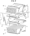
- a membrane exchanger of the present invention can be manufactured as a dual unit having sides 56 sufficient in size to cover two separate exchangers 58 and 60.
- a dual unit exchanger may be preferable to a single compartment exchanger of the same capacity.
- it may be easier to manufacture a double compartment exchanger than one large exchanger with a membrane having the same surface area.
- a double compartment exchanger may be more compact than one large compartment exchanger of the same capacity.
- the dual compartment permits a physician to increase the oxygenation rate during a treatment session if the patient requires more oxygenation than originally foreseen.
- Each of exchangers 58 and 60 are substantially identical to the exchanger illustrated in Fig. 1.
- the dual unit includes a pair of folded sheets 10,10'; a casing made up of two subcasings 12,12', and a pair of covers 36,36'.
- the exchangers 58 and 60 are held together by a pair of side walls 70 and 72 that serve as side walls for both of the exchangers 58 and 60.
- Each of walls 70 and 72 have an intermediate portion 71 and 73, respectively, that extends between and connects exchanger subunits 58 and 60.
- This final step is preferably accomplished using the heat welding technique described in connection with Fig. 1, except that with the dual unit, the edges of both subunits must be simultaneously heated along with a respective side wall, and then the respective side wall is mated with both subunits at the same time, and permitted to cool to thereby form a leak-proof bond with both subunits.
- a third embodiment of the invention illustrated in Figs. 5-7 is similar to the embodiment of Fig. 4, with the addition of structure including a heat exchanger.
- the third embodiment of the invention includes a pair of oxygenators 58' and 60' connected to heat exchanger 74, and the oxygenators may be assembled in the manner described in connection with Fig. 4.
- Heat exchanger 74 includes a blood inlet 76 and a blood outlet 78, as schematically illustrated in Fig. 7. The blood inlet and outlets permit blood to flow on one side of folded exchanger sheet 80 located within casing 82.
- heat exchanger 74 includes a heat exchange fluid inlet 84 and outlet 86 (illustrated in Fig. 5) for permitting heat exchange fluid to circulate on a side of folded exchanger sheet 80 opposite to the side on which blood flows.
- Exchanger sheet 80 is made of a non-permeable material such as stainless steel foil or thin plastic, and in the latter case, may be constructed in a manner described in connection with Fig. 1. Alternatively, the entire heat exchanger 74 including casing 82 may be constructed of stainless steel. A temperature probe 108 extends into the inlet manifold 46' of oxygenator 58' to permit measurement of blood temperature.
- Oxygenator 58' includes a pair of blood outlet ports 88 and 90, and a pair of blood inlet ports 92 and 94.
- the blood outlet port 78 of heat exchanger 74 is connected to blood inlet port 92 on manifold 46' of oxygenator 58', and the outlet port 90 of manifold 48' is for connection to a cannula for return of oxygenated blood at a desired temperature to a patient under treatment.
- Blood outlet 90 may include a sample port 106 for permitting access to the treated blood before return to the patient.
- the remaining blood outlet port 88 and blood inlet port 94 permit oxygenator 58' to be connected to oxygenator 60' for use when a single oxygenator is insufficient for a specific treatment.
- Oxygenator 60' includes a single blood inlet 96 and a single blood outlet 98, which are respectively connected to blood outlet 88 and blood inlet 94 of oxygenator 58' through lines 100 and 102, respectively.
- a degassing port 112 is provided proximate to blood inlet 96 for permitting excess gas to escape from the blood side of the circuit.
- degassing port 112 is connected to a cardiotomy reservoir 114 by tubing fitted with a valve, which allows for degassing of the blood chamber without the need for recirculation. If, during a treatment session the second compartment 60' is needed and if no degassing port 112 were to be provided, a recirculation procedure would be necessary in order to degas the second compartment 60'.
- a rotatable support 110 is mounted atop the integrated unit for supporting the cardiotomy reservoir 114, allowing for the shortest possible connection between the reservoir and a blood circulation pump. This structure is preferred because it is always desirable, in an extracorporeal blood circuit, to limit the amount of blood circulating outside of the body.
- each of oxygenators 58' and 60' are provided with oxygen inlet and outlet manifolds 20' and 22', respectively, for circulating oxygen on a side of membrane 10' opposite the side on which blood flows.
- Fig. 7 During cardiac surgery when the human lungs are dysfunctional, blood is withdrawn from a patient and is supplied to blood inlet line 104 via a pump (not shown). The blood enters heat exchanger 74 through blood inlet port 76 where it flows between the pleats on one side of heat exchange sheet 80. Simultaneously, heat exchange fluid is circulated through the pleats on an opposite side of sheet 80, the heat exchange fluid being circulated through inlet and outlet ports, 84 and 86, respectively (illustrated in Fig. 5). Heat transfer occurs across sheet 80, thereby allowing the temperature of blood to be adjusted to a desired value.
- Oxygenator 60' functions in a substantially identical manner to oxygenator 58' except that the single blood outlet 98 of oxygenator 60' is connected to the second blood inlet 94 of oxygenator 58' for reinfusion into a patient through blood outlet 90.
Abstract
Description
Claims (14)
- A blood oxygenator comprising:a first compartment having a closed casing (12) divided by a folded sheet of membrane material (10) to form a first blood chamber and a first gas chamber, the casing (12) having first (46) and second (48) spaced apart manifolds in fluid communication with the first blood chamber, the first and second manifolds each having an inlet and an outlet;a second compartment interconnected with the first compartment and having a closed casing (12') divided by a folded sheet of membrane material (10') to form a second blood chamber and a second gas chamber, the casing having third and fourth spaced apart manifolds in fluid communication with the second blood chamber, the third manifold having an inlet and the fourth manifold having an outlet; characterized bya first conduit (100) connecting the outlet (88) of the first manifold to the inlet (96) of the third manifold; anda second conduit (102) connecting the outlet (98) of the fourth manifold to the inlet (94) of the second manifold.
- A blood oxygenator according to claim 1 characterized in that the first and second compartments are interconnected so that the first and second blood chambers face each other.
- A blood oxygenator according to claim 1 or 2 further comprising means for selectively closing the first and second conduits (100, 102).
- A blood oxygenator according to claim 3 characterized in that the closing means includes clamps and the first and second conduits include flexible tubes.
- A blood oxygenator according to any of claims 1 to 4 further comprising:a heat exchanger (74) having a closed casing (82) divided by a folded sheet of exchanger material (80) to form a third blood chamber and a heat transfer fluid chamber, the casing having fifth and sixth spaced apart manifolds in fluid communication with the third blood chamber, the fifth manifold having an inlet (76) and the sixth manifold having an outlet (78);a third conduit (104) connecting the inlet of the fifth manifold to a blood reservoir; anda fourth conduit connecting the outlet (78) of the sixth manifold to the inlet (92) of the first manifold (46').
- A blood oxygenator according to claim 5 characterized in that the first and second compartments are interconnected with a space therebetween, the third conduit (104) extending through the space.
- A blood oxygenator according to claim 5 or 6 characterized in that the heat exchanger casing (82) and the folded sheet of exchanger material (80) are constructed of a plastic material.
- A blood oxygenator according to claim 5 or 6 characterized in that the heat exchanger casing (82) and the folded sheet of exchanger material (80) are made of metal.
- A blood oxygenator according to claim 8 characterized in that the metal is stainless steel.
- A blood oxygenator according to any one of the preceding claims characterized in that the second compartment further comprises a closable vent in fluid communication with the second blood chamber.
- A blood oxygenator according to any one of the preceding claims, wherein
said casing (12) of at least said first compartment has walls (16,18) with distal edges (28,30) covered with end portions (32,34) of the sheet material (10); and
said casing (12) of at least said first compartment has a cover (36) affixed to the casing by melting a portion of the cover and in contact with the sheet material (10) covering the distal edges of the walls. - A blood oxygenator according to any one of the preceding claims, wherein said membrane material (10) is sandwiched between two plies of netting material.
- A blood oxygenator according to any one of the preceding claims further comprising a rotatable reservoir support (110).
- A method of manufacturing a blood oxygenator, comprising the steps of providing the features of a blood oxygenator as defined in any one of the preceding claims.
Applications Claiming Priority (3)
| Application Number | Priority Date | Filing Date | Title |
|---|---|---|---|
| US970781 | 1992-11-03 | ||
| US07/970,781 US5470531A (en) | 1992-11-03 | 1992-11-03 | Exchanger and method for manufacturing the same |
| EP93307011A EP0596599B1 (en) | 1992-11-03 | 1993-09-06 | Exchanger and method for manufacturing the same |
Related Parent Applications (1)
| Application Number | Title | Priority Date | Filing Date |
|---|---|---|---|
| EP93307011A Division EP0596599B1 (en) | 1992-11-03 | 1993-09-06 | Exchanger and method for manufacturing the same |
Publications (2)
| Publication Number | Publication Date |
|---|---|
| EP0885618A1 true EP0885618A1 (en) | 1998-12-23 |
| EP0885618B1 EP0885618B1 (en) | 2002-11-13 |
Family
ID=25517509
Family Applications (2)
| Application Number | Title | Priority Date | Filing Date |
|---|---|---|---|
| EP98109192A Expired - Lifetime EP0885618B1 (en) | 1992-11-03 | 1993-09-06 | Blood oxygenator |
| EP93307011A Expired - Lifetime EP0596599B1 (en) | 1992-11-03 | 1993-09-06 | Exchanger and method for manufacturing the same |
Family Applications After (1)
| Application Number | Title | Priority Date | Filing Date |
|---|---|---|---|
| EP93307011A Expired - Lifetime EP0596599B1 (en) | 1992-11-03 | 1993-09-06 | Exchanger and method for manufacturing the same |
Country Status (5)
| Country | Link |
|---|---|
| US (2) | US5470531A (en) |
| EP (2) | EP0885618B1 (en) |
| JP (1) | JP2502924B2 (en) |
| CA (1) | CA2107613C (en) |
| DE (2) | DE69322485T2 (en) |
Cited By (2)
| Publication number | Priority date | Publication date | Assignee | Title |
|---|---|---|---|---|
| EP1870119A1 (en) * | 2006-06-20 | 2007-12-26 | Eurosets S.r.l. | Set of units for a device integrated in an extracorporeal blood circuit |
| CN103877633A (en) * | 2014-04-14 | 2014-06-25 | 东莞科威医疗器械有限公司 | Membrane oxygenator |
Families Citing this family (16)
| Publication number | Priority date | Publication date | Assignee | Title |
|---|---|---|---|---|
| US5514335A (en) * | 1993-10-25 | 1996-05-07 | Minnesota Mining And Manufacturing Company | Blood oxygenation system and reservoir and method of manufacture |
| US6045752A (en) * | 1996-03-18 | 2000-04-04 | Medtronic, Inc. | Blood oxygenator with waterless heat exchanger |
| US5997816A (en) * | 1997-05-14 | 1999-12-07 | Medtronic Avecor Cardiovascular, Inc. | Heat exchanger for medical applications |
| US6497841B1 (en) | 1997-07-22 | 2002-12-24 | Medtronic, Inc. | Prevention of electrical discharges in polymeric heat exchangers |
| DE19833366C1 (en) * | 1998-07-24 | 1999-12-02 | Soehner Kunststofftechnik Gmbh | Counter flow type heat exchanger made from plastic, used for heating and climate control in buildings |
| US6113782A (en) * | 1998-07-28 | 2000-09-05 | Terumo Cardiovascular Systems Corporation | Potting of tubular bundles in housing |
| US6186223B1 (en) * | 1998-08-27 | 2001-02-13 | Zeks Air Drier Corporation | Corrugated folded plate heat exchanger |
| US6438936B1 (en) | 2000-05-16 | 2002-08-27 | Elliott Energy Systems, Inc. | Recuperator for use with turbine/turbo-alternator |
| ATE342480T1 (en) * | 2000-07-28 | 2006-11-15 | Honda Motor Co Ltd | MULTIPURPOSE MICROCOMPONENT WITH MICROCHANNELS |
| DE10302948A1 (en) * | 2003-01-24 | 2004-08-05 | Behr Gmbh & Co. Kg | Heat exchanger, in particular exhaust gas cooler for motor vehicles |
| US7150099B2 (en) * | 2004-03-30 | 2006-12-19 | Catacel Corp. | Heat exchanger for high-temperature applications |
| CN100510606C (en) * | 2004-09-28 | 2009-07-08 | 株式会社T.Rad | Heat exchanger |
| DE102008011970A1 (en) * | 2008-02-29 | 2009-09-03 | Hochschule Bremen | Heat exchanger for fluid media |
| US8545754B2 (en) | 2009-04-23 | 2013-10-01 | Medtronic, Inc. | Radial design oxygenator with heat exchanger |
| TWI612999B (en) | 2011-10-03 | 2018-02-01 | 恩特葛瑞斯公司 | Modular filter cassette |
| JP2016508200A (en) | 2012-10-01 | 2016-03-17 | インテグリス・インコーポレーテッド | Concatenation system and concatenation method |
Citations (6)
| Publication number | Priority date | Publication date | Assignee | Title |
|---|---|---|---|---|
| US3370710A (en) * | 1966-05-11 | 1968-02-27 | Research Corp | Compact blood dialyzer with a pleated membrane therein |
| US3998593A (en) * | 1973-07-02 | 1976-12-21 | Seisan Kaihatsu Kagaku Kenkyusho | Membrane blood oxygenator |
| US4255263A (en) * | 1978-08-10 | 1981-03-10 | Costruzioni E Impianti S.P.A. Fiat Engineering | Stacked assembly for reverse osmosis |
| GB2082475A (en) * | 1980-08-28 | 1982-03-10 | Wada Juro | Artificial lung device |
| US4556489A (en) * | 1983-03-09 | 1985-12-03 | Shiley Incorporated | Membrane oxygenator |
| US4656004A (en) * | 1985-05-17 | 1987-04-07 | Cobe Laboratories, Inc. | Medical heat exchange |
Family Cites Families (20)
| Publication number | Priority date | Publication date | Assignee | Title |
|---|---|---|---|---|
| US3489647A (en) * | 1964-05-06 | 1970-01-13 | Dow Corning | Artificial organ for membrane dialysis of biological fluids |
| BE790299A (en) * | 1972-03-10 | 1973-02-15 | Atomic Energy Commission | FOLDED DIAPHRAGM DIALYZER, AND PROCESS FOR FORMING IT |
| US4028252A (en) * | 1975-06-04 | 1977-06-07 | Extracorporeal Medical Specialties Inc. | Accordion fold flat plate dialyzer |
| US4199457A (en) * | 1975-11-05 | 1980-04-22 | Esmond William G | Pleated artificial kidney |
| US4431539A (en) * | 1977-03-21 | 1984-02-14 | American Hospital Supply Corp. | Semipermeable membrane mass transfer apparatus and method for making same |
| US4163721A (en) * | 1977-04-04 | 1979-08-07 | Cobe Laboratories, Inc. | Edge sealed pleated membrane |
| DE2803344C3 (en) * | 1978-01-26 | 1981-09-24 | Sartorius GmbH, 3400 Göttingen | Device for mass transfer between fluids with the interposition of a membrane |
| US4267044A (en) * | 1978-04-10 | 1981-05-12 | Nl Industries, Inc. | Thixotropic polyurethane compositions as sealants for membrane separatory devices |
| US4228125A (en) * | 1978-06-20 | 1980-10-14 | Cobe Laboratories, Inc. | Gas exchange apparatus |
| US4246121A (en) * | 1978-11-17 | 1981-01-20 | Cobe Laboratories, Inc. | Fluid flow transfer device with formed-in-place manifold gasket and method of making same |
| US4239625A (en) * | 1979-04-25 | 1980-12-16 | Cobe Laboratories, Inc. | Potting pleated membrane |
| US4318813A (en) * | 1980-06-30 | 1982-03-09 | Baxter Travenol Laboratories, Inc. | Membrane plasmapheresis module |
| US4469659B1 (en) * | 1982-04-26 | 1997-07-29 | Cobe Lab | Sampling device for blood oxygenator |
| US4455230A (en) * | 1982-04-26 | 1984-06-19 | Cobe Laboratories, Inc. | Pleated membrane transfer device utilizing potting and thixotropic adhesive |
| US4929354A (en) * | 1982-05-28 | 1990-05-29 | Cuno, Incorporated | Filter element having microporous membrane |
| US4645645A (en) * | 1985-04-04 | 1987-02-24 | Renal Systems, Inc. | Oxygenator having an improved heat exchanger |
| US4663125A (en) * | 1985-05-17 | 1987-05-05 | Cobe Laboratories, Inc. | Membrane medical device |
| US4863603A (en) * | 1987-04-09 | 1989-09-05 | Sartorius Gmbh | Filter unit for separating precipitates containing cholesterol |
| EP0285993A3 (en) * | 1987-04-09 | 1991-05-22 | Sartorius Ag | Filter element for separating cholesterol from blood plasma and disposable filter unit completed by a housing |
| FR2643268B1 (en) * | 1989-02-23 | 1993-12-17 | Hospal Industrie | FLAT MEMBRANE FLUID TREATMENT APPARATUS |
-
1992
- 1992-11-03 US US07/970,781 patent/US5470531A/en not_active Expired - Lifetime
-
1993
- 1993-09-06 DE DE69322485T patent/DE69322485T2/en not_active Expired - Lifetime
- 1993-09-06 EP EP98109192A patent/EP0885618B1/en not_active Expired - Lifetime
- 1993-09-06 EP EP93307011A patent/EP0596599B1/en not_active Expired - Lifetime
- 1993-09-06 DE DE69332491T patent/DE69332491T2/en not_active Expired - Lifetime
- 1993-10-04 CA CA002107613A patent/CA2107613C/en not_active Expired - Fee Related
- 1993-10-20 JP JP5262022A patent/JP2502924B2/en not_active Expired - Fee Related
-
1994
- 1994-07-11 US US08/272,524 patent/US5468449A/en not_active Expired - Lifetime
Patent Citations (6)
| Publication number | Priority date | Publication date | Assignee | Title |
|---|---|---|---|---|
| US3370710A (en) * | 1966-05-11 | 1968-02-27 | Research Corp | Compact blood dialyzer with a pleated membrane therein |
| US3998593A (en) * | 1973-07-02 | 1976-12-21 | Seisan Kaihatsu Kagaku Kenkyusho | Membrane blood oxygenator |
| US4255263A (en) * | 1978-08-10 | 1981-03-10 | Costruzioni E Impianti S.P.A. Fiat Engineering | Stacked assembly for reverse osmosis |
| GB2082475A (en) * | 1980-08-28 | 1982-03-10 | Wada Juro | Artificial lung device |
| US4556489A (en) * | 1983-03-09 | 1985-12-03 | Shiley Incorporated | Membrane oxygenator |
| US4656004A (en) * | 1985-05-17 | 1987-04-07 | Cobe Laboratories, Inc. | Medical heat exchange |
Cited By (4)
| Publication number | Priority date | Publication date | Assignee | Title |
|---|---|---|---|---|
| EP1870119A1 (en) * | 2006-06-20 | 2007-12-26 | Eurosets S.r.l. | Set of units for a device integrated in an extracorporeal blood circuit |
| US7621885B2 (en) | 2006-06-20 | 2009-11-24 | Eurosets S.R.L. | Set of units for a device integrated in an extracorporeal blood circuit |
| CN103877633A (en) * | 2014-04-14 | 2014-06-25 | 东莞科威医疗器械有限公司 | Membrane oxygenator |
| CN103877633B (en) * | 2014-04-14 | 2015-12-30 | 东莞科威医疗器械有限公司 | Membrane oxygenator |
Also Published As
| Publication number | Publication date |
|---|---|
| EP0885618B1 (en) | 2002-11-13 |
| DE69332491D1 (en) | 2002-12-19 |
| US5468449A (en) | 1995-11-21 |
| CA2107613A1 (en) | 1994-05-04 |
| DE69322485D1 (en) | 1999-01-21 |
| EP0596599B1 (en) | 1998-12-09 |
| DE69322485T2 (en) | 1999-04-29 |
| CA2107613C (en) | 1999-05-04 |
| EP0596599A2 (en) | 1994-05-11 |
| JP2502924B2 (en) | 1996-05-29 |
| EP0596599A3 (en) | 1995-02-15 |
| JPH06225937A (en) | 1994-08-16 |
| DE69332491T2 (en) | 2003-05-08 |
| US5470531A (en) | 1995-11-28 |
Similar Documents
| Publication | Publication Date | Title |
|---|---|---|
| EP0885618B1 (en) | Blood oxygenator | |
| US5338512A (en) | Method for oxygenation of a patient's blood | |
| US4138288A (en) | Method and apparatus for oxygenating and regulating the temperature of blood | |
| US5225161A (en) | Integrated membrane blood oxygenator/heat exchanger | |
| US4111659A (en) | Mass and heat transfer exchange apparatus | |
| USRE36774E (en) | Cylindrical blood heater/oxygenator | |
| US5312589A (en) | Gas transfer apparatus | |
| US6117390A (en) | Compact blood oxygenator utilizing longitudinally interspersed transversely extending heat exchanger conduits and oxygenator fibers | |
| EP0394221B1 (en) | Outside perfusion type blood oxygenator | |
| US5578267A (en) | Cylindrical blood heater/oxygenator | |
| US4256692A (en) | Membrane oxygenator | |
| JPS6339262B2 (en) | ||
| WO1990007943A1 (en) | Oxygenator wedge configuration | |
| JPH0622615B2 (en) | Hollow fiber blood oxygenator | |
| US4173537A (en) | Integral artificial kidney unit | |
| EP0054557A1 (en) | Membrane plasmapheresis module | |
| CA1145634A (en) | Blood oxygenator with integral heat exchanger | |
| WO1980002806A1 (en) | Blood perfusion units | |
| WO2011013075A1 (en) | Oxygenator device | |
| JP3609835B2 (en) | Blood heat exchange system | |
| JPS63139562A (en) | Hollow yarn type artificial lung | |
| US4179364A (en) | Diffusion device for blood | |
| Bramson et al. | Design and performance of a new membrane lung | |
| US20220378991A1 (en) | Vacuum assisted self-priming heart lung machine in a box | |
| JPS62691Y2 (en) |
Legal Events
| Date | Code | Title | Description |
|---|---|---|---|
| PUAI | Public reference made under article 153(3) epc to a published international application that has entered the european phase |
Free format text: ORIGINAL CODE: 0009012 |
|
| AC | Divisional application: reference to earlier application |
Ref document number: 596599 Country of ref document: EP |
|
| AK | Designated contracting states |
Kind code of ref document: A1 Designated state(s): DE FR GB |
|
| 17P | Request for examination filed |
Effective date: 19981117 |
|
| RAP1 | Party data changed (applicant data changed or rights of an application transferred) |
Owner name: COBE CARDIOVASCULAR, INC. |
|
| 17Q | First examination report despatched |
Effective date: 20000518 |
|
| GRAG | Despatch of communication of intention to grant |
Free format text: ORIGINAL CODE: EPIDOS AGRA |
|
| RTI1 | Title (correction) |
Free format text: BLOOD OXYGENATOR |
|
| GRAG | Despatch of communication of intention to grant |
Free format text: ORIGINAL CODE: EPIDOS AGRA |
|
| GRAH | Despatch of communication of intention to grant a patent |
Free format text: ORIGINAL CODE: EPIDOS IGRA |
|
| GRAH | Despatch of communication of intention to grant a patent |
Free format text: ORIGINAL CODE: EPIDOS IGRA |
|
| GRAA | (expected) grant |
Free format text: ORIGINAL CODE: 0009210 |
|
| AC | Divisional application: reference to earlier application |
Ref document number: 596599 Country of ref document: EP |
|
| AK | Designated contracting states |
Kind code of ref document: B1 Designated state(s): DE FR GB |
|
| PG25 | Lapsed in a contracting state [announced via postgrant information from national office to epo] |
Ref country code: FR Free format text: LAPSE BECAUSE OF FAILURE TO SUBMIT A TRANSLATION OF THE DESCRIPTION OR TO PAY THE FEE WITHIN THE PRESCRIBED TIME-LIMIT Effective date: 20021113 |
|
| REG | Reference to a national code |
Ref country code: GB Ref legal event code: FG4D |
|
| REF | Corresponds to: |
Ref document number: 69332491 Country of ref document: DE Date of ref document: 20021219 |
|
| EN | Fr: translation not filed | ||
| PG25 | Lapsed in a contracting state [announced via postgrant information from national office to epo] |
Ref country code: GB Free format text: LAPSE BECAUSE OF NON-PAYMENT OF DUE FEES Effective date: 20030906 |
|
| PLBE | No opposition filed within time limit |
Free format text: ORIGINAL CODE: 0009261 |
|
| STAA | Information on the status of an ep patent application or granted ep patent |
Free format text: STATUS: NO OPPOSITION FILED WITHIN TIME LIMIT |
|
| 26N | No opposition filed |
Effective date: 20030814 |
|
| GBPC | Gb: european patent ceased through non-payment of renewal fee |
Effective date: 20030906 |
|
| PGFP | Annual fee paid to national office [announced via postgrant information from national office to epo] |
Ref country code: DE Payment date: 20100901 Year of fee payment: 18 |
|
| REG | Reference to a national code |
Ref country code: DE Ref legal event code: R119 Ref document number: 69332491 Country of ref document: DE Effective date: 20120403 |
|
| PG25 | Lapsed in a contracting state [announced via postgrant information from national office to epo] |
Ref country code: DE Free format text: LAPSE BECAUSE OF NON-PAYMENT OF DUE FEES Effective date: 20120403 |