EP1069444A2 - UV radiation system having materials for selectively attenuating radiation - Google Patents
UV radiation system having materials for selectively attenuating radiation Download PDFInfo
- Publication number
- EP1069444A2 EP1069444A2 EP00305903A EP00305903A EP1069444A2 EP 1069444 A2 EP1069444 A2 EP 1069444A2 EP 00305903 A EP00305903 A EP 00305903A EP 00305903 A EP00305903 A EP 00305903A EP 1069444 A2 EP1069444 A2 EP 1069444A2
- Authority
- EP
- European Patent Office
- Prior art keywords
- oxide
- radiation
- attenuating
- materials
- isopropanol
- Prior art date
- Legal status (The legal status is an assumption and is not a legal conclusion. Google has not performed a legal analysis and makes no representation as to the accuracy of the status listed.)
- Granted
Links
- 239000000463 material Substances 0.000 title claims abstract description 289
- 230000005855 radiation Effects 0.000 title claims abstract description 231
- 230000006378 damage Effects 0.000 claims abstract description 17
- VLKZOEOYAKHREP-UHFFFAOYSA-N n-Hexane Chemical compound CCCCCC VLKZOEOYAKHREP-UHFFFAOYSA-N 0.000 claims description 57
- 238000000576 coating method Methods 0.000 claims description 54
- 239000007787 solid Substances 0.000 claims description 53
- 239000007788 liquid Substances 0.000 claims description 47
- MRELNEQAGSRDBK-UHFFFAOYSA-N lanthanum(3+);oxygen(2-) Chemical compound [O-2].[O-2].[O-2].[La+3].[La+3] MRELNEQAGSRDBK-UHFFFAOYSA-N 0.000 claims description 42
- 239000011248 coating agent Substances 0.000 claims description 38
- FZJCXIDLUFPGPP-UHFFFAOYSA-N propan-2-ol;toluene Chemical compound CC(C)O.CC1=CC=CC=C1 FZJCXIDLUFPGPP-UHFFFAOYSA-N 0.000 claims description 37
- -1 polysiloxane Polymers 0.000 claims description 29
- XNWFRZJHXBZDAG-UHFFFAOYSA-N 2-METHOXYETHANOL Chemical compound COCCO XNWFRZJHXBZDAG-UHFFFAOYSA-N 0.000 claims description 28
- 239000011230 binding agent Substances 0.000 claims description 28
- KFZMGEQAYNKOFK-UHFFFAOYSA-N Isopropanol Chemical compound CC(C)O KFZMGEQAYNKOFK-UHFFFAOYSA-N 0.000 claims description 27
- 239000000203 mixture Substances 0.000 claims description 27
- TZCXTZWJZNENPQ-UHFFFAOYSA-L barium sulfate Chemical compound [Ba+2].[O-]S([O-])(=O)=O TZCXTZWJZNENPQ-UHFFFAOYSA-L 0.000 claims description 26
- 239000011521 glass Substances 0.000 claims description 17
- 239000002019 doping agent Substances 0.000 claims description 14
- OKKJLVBELUTLKV-UHFFFAOYSA-N Methanol Chemical compound OC OKKJLVBELUTLKV-UHFFFAOYSA-N 0.000 claims description 12
- SIWVEOZUMHYXCS-UHFFFAOYSA-N oxo(oxoyttriooxy)yttrium Chemical compound O=[Y]O[Y]=O SIWVEOZUMHYXCS-UHFFFAOYSA-N 0.000 claims description 12
- 229910052911 sodium silicate Inorganic materials 0.000 claims description 12
- 239000004115 Sodium Silicate Substances 0.000 claims description 11
- CPLXHLVBOLITMK-UHFFFAOYSA-N magnesium oxide Inorganic materials [Mg]=O CPLXHLVBOLITMK-UHFFFAOYSA-N 0.000 claims description 11
- 239000000395 magnesium oxide Substances 0.000 claims description 11
- AXZKOIWUVFPNLO-UHFFFAOYSA-N magnesium;oxygen(2-) Chemical compound [O-2].[Mg+2] AXZKOIWUVFPNLO-UHFFFAOYSA-N 0.000 claims description 11
- UZLYXNNZYFBAQO-UHFFFAOYSA-N oxygen(2-);ytterbium(3+) Chemical compound [O-2].[O-2].[O-2].[Yb+3].[Yb+3] UZLYXNNZYFBAQO-UHFFFAOYSA-N 0.000 claims description 11
- NTHWMYGWWRZVTN-UHFFFAOYSA-N sodium silicate Chemical compound [Na+].[Na+].[O-][Si]([O-])=O NTHWMYGWWRZVTN-UHFFFAOYSA-N 0.000 claims description 11
- HEDRZPFGACZZDS-UHFFFAOYSA-N Chloroform Chemical compound ClC(Cl)Cl HEDRZPFGACZZDS-UHFFFAOYSA-N 0.000 claims description 10
- 230000000903 blocking effect Effects 0.000 claims description 10
- 230000001681 protective effect Effects 0.000 claims description 10
- 229910003454 ytterbium oxide Inorganic materials 0.000 claims description 10
- 229940075624 ytterbium oxide Drugs 0.000 claims description 10
- LFQSCWFLJHTTHZ-UHFFFAOYSA-N Ethanol Chemical compound CCO LFQSCWFLJHTTHZ-UHFFFAOYSA-N 0.000 claims description 9
- 230000002238 attenuated effect Effects 0.000 claims description 9
- 229910052751 metal Inorganic materials 0.000 claims description 9
- 239000002184 metal Substances 0.000 claims description 9
- 229910052727 yttrium Inorganic materials 0.000 claims description 9
- VWQVUPCCIRVNHF-UHFFFAOYSA-N yttrium atom Chemical compound [Y] VWQVUPCCIRVNHF-UHFFFAOYSA-N 0.000 claims description 9
- VQCBHWLJZDBHOS-UHFFFAOYSA-N erbium(iii) oxide Chemical compound O=[Er]O[Er]=O VQCBHWLJZDBHOS-UHFFFAOYSA-N 0.000 claims description 8
- ORUIBWPALBXDOA-UHFFFAOYSA-L magnesium fluoride Chemical compound [F-].[F-].[Mg+2] ORUIBWPALBXDOA-UHFFFAOYSA-L 0.000 claims description 8
- 229910044991 metal oxide Inorganic materials 0.000 claims description 8
- 150000004706 metal oxides Chemical class 0.000 claims description 8
- 239000000843 powder Substances 0.000 claims description 8
- 239000011343 solid material Substances 0.000 claims description 8
- 229910052769 Ytterbium Inorganic materials 0.000 claims description 7
- 229910052782 aluminium Inorganic materials 0.000 claims description 7
- XAGFODPZIPBFFR-UHFFFAOYSA-N aluminium Chemical compound [Al] XAGFODPZIPBFFR-UHFFFAOYSA-N 0.000 claims description 7
- 229910001635 magnesium fluoride Inorganic materials 0.000 claims description 7
- NAWDYIZEMPQZHO-UHFFFAOYSA-N ytterbium Chemical compound [Yb] NAWDYIZEMPQZHO-UHFFFAOYSA-N 0.000 claims description 7
- IJGRMHOSHXDMSA-UHFFFAOYSA-N Atomic nitrogen Chemical compound N#N IJGRMHOSHXDMSA-UHFFFAOYSA-N 0.000 claims description 6
- 229910002113 barium titanate Inorganic materials 0.000 claims description 6
- 229920001778 nylon Polymers 0.000 claims description 6
- 229920001296 polysiloxane Polymers 0.000 claims description 6
- 239000000126 substance Substances 0.000 claims description 6
- PPNFILUQDVDXDA-UHFFFAOYSA-K 2-ethylhexanoate;lanthanum(3+) Chemical compound [La+3].CCCCC(CC)C([O-])=O.CCCCC(CC)C([O-])=O.CCCCC(CC)C([O-])=O PPNFILUQDVDXDA-UHFFFAOYSA-K 0.000 claims description 5
- LIOAXSVBTBXEEN-UHFFFAOYSA-N 2-methoxyethanolate;ytterbium(3+) Chemical compound [Yb+3].COCC[O-].COCC[O-].COCC[O-] LIOAXSVBTBXEEN-UHFFFAOYSA-N 0.000 claims description 5
- DNIAPMSPPWPWGF-UHFFFAOYSA-N Propylene glycol Chemical compound CC(O)CO DNIAPMSPPWPWGF-UHFFFAOYSA-N 0.000 claims description 5
- 150000001722 carbon compounds Chemical class 0.000 claims description 5
- XPEKDHWAGKXPST-UHFFFAOYSA-N dysprosium(3+);propan-2-olate Chemical compound [Dy+3].CC(C)[O-].CC(C)[O-].CC(C)[O-] XPEKDHWAGKXPST-UHFFFAOYSA-N 0.000 claims description 5
- 239000007789 gas Substances 0.000 claims description 5
- OWCYYNSBGXMRQN-UHFFFAOYSA-N holmium(3+);oxygen(2-) Chemical compound [O-2].[O-2].[O-2].[Ho+3].[Ho+3] OWCYYNSBGXMRQN-UHFFFAOYSA-N 0.000 claims description 5
- ZXGACMORJMVLLF-UHFFFAOYSA-N lanthanum(3+);2-methoxyethanolate Chemical compound [La+3].COCC[O-].COCC[O-].COCC[O-] ZXGACMORJMVLLF-UHFFFAOYSA-N 0.000 claims description 5
- SORGMJIXNUWMMR-UHFFFAOYSA-N lanthanum(3+);propan-2-olate Chemical compound [La+3].CC(C)[O-].CC(C)[O-].CC(C)[O-] SORGMJIXNUWMMR-UHFFFAOYSA-N 0.000 claims description 5
- JLRJWBUSTKIQQH-UHFFFAOYSA-K lanthanum(3+);triacetate Chemical compound [La+3].CC([O-])=O.CC([O-])=O.CC([O-])=O JLRJWBUSTKIQQH-UHFFFAOYSA-K 0.000 claims description 5
- 229910003447 praseodymium oxide Inorganic materials 0.000 claims description 5
- RAKJHSBPOPJWKI-UHFFFAOYSA-N propan-2-olate;ytterbium(3+) Chemical compound [Yb+3].CC(C)[O-].CC(C)[O-].CC(C)[O-] RAKJHSBPOPJWKI-UHFFFAOYSA-N 0.000 claims description 5
- FKTOIHSPIPYAPE-UHFFFAOYSA-N samarium(iii) oxide Chemical compound [O-2].[O-2].[O-2].[Sm+3].[Sm+3] FKTOIHSPIPYAPE-UHFFFAOYSA-N 0.000 claims description 5
- 239000012703 sol-gel precursor Substances 0.000 claims description 5
- POILWHVDKZOXJZ-ARJAWSKDSA-M (z)-4-oxopent-2-en-2-olate Chemical compound C\C([O-])=C\C(C)=O POILWHVDKZOXJZ-ARJAWSKDSA-M 0.000 claims description 4
- IXXNKQHBHUUTIC-UHFFFAOYSA-K 2-ethylhexanoate;samarium(3+) Chemical compound [Sm+3].CCCCC(CC)C([O-])=O.CCCCC(CC)C([O-])=O.CCCCC(CC)C([O-])=O IXXNKQHBHUUTIC-UHFFFAOYSA-K 0.000 claims description 4
- SAUDVIWCWWDSOF-UHFFFAOYSA-N 2-methoxyethanolate;samarium(3+) Chemical compound [Sm+3].COCC[O-].COCC[O-].COCC[O-] SAUDVIWCWWDSOF-UHFFFAOYSA-N 0.000 claims description 4
- RVDLHGSZWAELAU-UHFFFAOYSA-N 5-tert-butylthiophene-2-carbonyl chloride Chemical compound CC(C)(C)C1=CC=C(C(Cl)=O)S1 RVDLHGSZWAELAU-UHFFFAOYSA-N 0.000 claims description 4
- 229910052691 Erbium Inorganic materials 0.000 claims description 4
- 229910052689 Holmium Inorganic materials 0.000 claims description 4
- UQSXHKLRYXJYBZ-UHFFFAOYSA-N Iron oxide Chemical compound [Fe]=O UQSXHKLRYXJYBZ-UHFFFAOYSA-N 0.000 claims description 4
- BOTDANWDWHJENH-UHFFFAOYSA-N Tetraethyl orthosilicate Chemical compound CCO[Si](OCC)(OCC)OCC BOTDANWDWHJENH-UHFFFAOYSA-N 0.000 claims description 4
- JRPBQTZRNDNNOP-UHFFFAOYSA-N barium titanate Chemical compound [Ba+2].[Ba+2].[O-][Ti]([O-])([O-])[O-] JRPBQTZRNDNNOP-UHFFFAOYSA-N 0.000 claims description 4
- 230000008859 change Effects 0.000 claims description 4
- 238000007598 dipping method Methods 0.000 claims description 4
- UYAHIZSMUZPPFV-UHFFFAOYSA-N erbium Chemical compound [Er] UYAHIZSMUZPPFV-UHFFFAOYSA-N 0.000 claims description 4
- KPBFDCICKGHVOX-UHFFFAOYSA-K erbium(3+);2-ethylhexanoate Chemical compound [Er+3].CCCCC(CC)C([O-])=O.CCCCC(CC)C([O-])=O.CCCCC(CC)C([O-])=O KPBFDCICKGHVOX-UHFFFAOYSA-K 0.000 claims description 4
- VOCNVTAXVORJBI-UHFFFAOYSA-N erbium(3+);propan-2-olate Chemical compound [Er+3].CC(C)[O-].CC(C)[O-].CC(C)[O-] VOCNVTAXVORJBI-UHFFFAOYSA-N 0.000 claims description 4
- 229910001940 europium oxide Inorganic materials 0.000 claims description 4
- AEBZCFFCDTZXHP-UHFFFAOYSA-N europium(3+);oxygen(2-) Chemical compound [O-2].[O-2].[O-2].[Eu+3].[Eu+3] AEBZCFFCDTZXHP-UHFFFAOYSA-N 0.000 claims description 4
- YBMRDBCBODYGJE-UHFFFAOYSA-N germanium oxide Inorganic materials O=[Ge]=O YBMRDBCBODYGJE-UHFFFAOYSA-N 0.000 claims description 4
- KJZYNXUDTRRSPN-UHFFFAOYSA-N holmium atom Chemical compound [Ho] KJZYNXUDTRRSPN-UHFFFAOYSA-N 0.000 claims description 4
- JYTUFVYWTIKZGR-UHFFFAOYSA-N holmium oxide Inorganic materials [O][Ho]O[Ho][O] JYTUFVYWTIKZGR-UHFFFAOYSA-N 0.000 claims description 4
- NUPYRUFSZUVIBV-UHFFFAOYSA-N holmium(3+);2-methoxyethanolate Chemical compound [Ho+3].COCC[O-].COCC[O-].COCC[O-] NUPYRUFSZUVIBV-UHFFFAOYSA-N 0.000 claims description 4
- NYLSGCTWRDYISF-UHFFFAOYSA-N holmium(3+);propan-2-olate Chemical compound [Ho+3].CC(C)[O-].CC(C)[O-].CC(C)[O-] NYLSGCTWRDYISF-UHFFFAOYSA-N 0.000 claims description 4
- YXOSSQSXCRVLJY-UHFFFAOYSA-N magnesium;2-methoxyethanolate Chemical compound COCCO[Mg]OCCOC YXOSSQSXCRVLJY-UHFFFAOYSA-N 0.000 claims description 4
- CRGZYKWWYNQGEC-UHFFFAOYSA-N magnesium;methanolate Chemical compound [Mg+2].[O-]C.[O-]C CRGZYKWWYNQGEC-UHFFFAOYSA-N 0.000 claims description 4
- MMKQUGHLEMYQSG-UHFFFAOYSA-N oxygen(2-);praseodymium(3+) Chemical compound [O-2].[O-2].[O-2].[Pr+3].[Pr+3] MMKQUGHLEMYQSG-UHFFFAOYSA-N 0.000 claims description 4
- HJCRVWSKQNDSPZ-UHFFFAOYSA-N propan-2-olate;samarium(3+) Chemical compound [Sm+3].CC(C)[O-].CC(C)[O-].CC(C)[O-] HJCRVWSKQNDSPZ-UHFFFAOYSA-N 0.000 claims description 4
- RUOJZAUFBMNUDX-UHFFFAOYSA-N propylene carbonate Chemical compound CC1COC(=O)O1 RUOJZAUFBMNUDX-UHFFFAOYSA-N 0.000 claims description 4
- 238000002310 reflectometry Methods 0.000 claims description 4
- 229910001954 samarium oxide Inorganic materials 0.000 claims description 4
- 229940075630 samarium oxide Drugs 0.000 claims description 4
- 239000011734 sodium Substances 0.000 claims description 4
- 238000005507 spraying Methods 0.000 claims description 4
- QBKTXRLYEHZACW-UHFFFAOYSA-K 2-ethylhexanoate;neodymium(3+) Chemical compound [Nd+3].CCCCC(CC)C([O-])=O.CCCCC(CC)C([O-])=O.CCCCC(CC)C([O-])=O QBKTXRLYEHZACW-UHFFFAOYSA-K 0.000 claims description 3
- QUTMHDXDLDUWCT-UHFFFAOYSA-N 2-methoxyethanolate;neodymium(3+) Chemical compound [Nd+3].COCC[O-].COCC[O-].COCC[O-] QUTMHDXDLDUWCT-UHFFFAOYSA-N 0.000 claims description 3
- 229920001651 Cyanoacrylate Polymers 0.000 claims description 3
- 229910052692 Dysprosium Inorganic materials 0.000 claims description 3
- DGAQECJNVWCQMB-PUAWFVPOSA-M Ilexoside XXIX Chemical compound C[C@@H]1CC[C@@]2(CC[C@@]3(C(=CC[C@H]4[C@]3(CC[C@@H]5[C@@]4(CC[C@@H](C5(C)C)OS(=O)(=O)[O-])C)C)[C@@H]2[C@]1(C)O)C)C(=O)O[C@H]6[C@@H]([C@H]([C@@H]([C@H](O6)CO)O)O)O.[Na+] DGAQECJNVWCQMB-PUAWFVPOSA-M 0.000 claims description 3
- FYYHWMGAXLPEAU-UHFFFAOYSA-N Magnesium Chemical compound [Mg] FYYHWMGAXLPEAU-UHFFFAOYSA-N 0.000 claims description 3
- 229910052779 Neodymium Inorganic materials 0.000 claims description 3
- 239000004677 Nylon Substances 0.000 claims description 3
- 239000004952 Polyamide Substances 0.000 claims description 3
- ZLMJMSJWJFRBEC-UHFFFAOYSA-N Potassium Chemical compound [K] ZLMJMSJWJFRBEC-UHFFFAOYSA-N 0.000 claims description 3
- WNLRTRBMVRJNCN-UHFFFAOYSA-N adipic acid Chemical compound OC(=O)CCCCC(O)=O WNLRTRBMVRJNCN-UHFFFAOYSA-N 0.000 claims description 3
- 229910000272 alkali metal oxide Inorganic materials 0.000 claims description 3
- 229910052788 barium Inorganic materials 0.000 claims description 3
- DSAJWYNOEDNPEQ-UHFFFAOYSA-N barium atom Chemical compound [Ba] DSAJWYNOEDNPEQ-UHFFFAOYSA-N 0.000 claims description 3
- QVQLCTNNEUAWMS-UHFFFAOYSA-N barium oxide Chemical compound [Ba]=O QVQLCTNNEUAWMS-UHFFFAOYSA-N 0.000 claims description 3
- ODINCKMPIJJUCX-UHFFFAOYSA-N calcium oxide Inorganic materials [Ca]=O ODINCKMPIJJUCX-UHFFFAOYSA-N 0.000 claims description 3
- 238000005266 casting Methods 0.000 claims description 3
- 238000007739 conversion coating Methods 0.000 claims description 3
- KBQHZAAAGSGFKK-UHFFFAOYSA-N dysprosium atom Chemical compound [Dy] KBQHZAAAGSGFKK-UHFFFAOYSA-N 0.000 claims description 3
- 229910003440 dysprosium oxide Inorganic materials 0.000 claims description 3
- SPQJTJAPBKMHMO-UHFFFAOYSA-K dysprosium(3+);2-ethylhexanoate Chemical compound [Dy+3].CCCCC(CC)C([O-])=O.CCCCC(CC)C([O-])=O.CCCCC(CC)C([O-])=O SPQJTJAPBKMHMO-UHFFFAOYSA-K 0.000 claims description 3
- RMGKHAGJLXBMRB-UHFFFAOYSA-N dysprosium(3+);2-methoxyethanolate Chemical compound [Dy+3].COCC[O-].COCC[O-].COCC[O-] RMGKHAGJLXBMRB-UHFFFAOYSA-N 0.000 claims description 3
- NLQFUUYNQFMIJW-UHFFFAOYSA-N dysprosium(iii) oxide Chemical compound O=[Dy]O[Dy]=O NLQFUUYNQFMIJW-UHFFFAOYSA-N 0.000 claims description 3
- 238000005530 etching Methods 0.000 claims description 3
- 229910000449 hafnium oxide Inorganic materials 0.000 claims description 3
- 150000004820 halides Chemical class 0.000 claims description 3
- 239000011777 magnesium Substances 0.000 claims description 3
- 229910052749 magnesium Inorganic materials 0.000 claims description 3
- 150000002739 metals Chemical class 0.000 claims description 3
- QEFYFXOXNSNQGX-UHFFFAOYSA-N neodymium atom Chemical compound [Nd] QEFYFXOXNSNQGX-UHFFFAOYSA-N 0.000 claims description 3
- PLDDOISOJJCEMH-UHFFFAOYSA-N neodymium(3+);oxygen(2-) Chemical compound [O-2].[O-2].[O-2].[Nd+3].[Nd+3] PLDDOISOJJCEMH-UHFFFAOYSA-N 0.000 claims description 3
- HZHUIQPXRWTHNF-UHFFFAOYSA-N neodymium(3+);propan-2-olate Chemical compound [Nd+3].CC(C)[O-].CC(C)[O-].CC(C)[O-] HZHUIQPXRWTHNF-UHFFFAOYSA-N 0.000 claims description 3
- 229910052757 nitrogen Inorganic materials 0.000 claims description 3
- 150000005677 organic carbonates Chemical class 0.000 claims description 3
- 238000010422 painting Methods 0.000 claims description 3
- RVZRBWKZFJCCIB-UHFFFAOYSA-N perfluorotributylamine Chemical compound FC(F)(F)C(F)(F)C(F)(F)C(F)(F)N(C(F)(F)C(F)(F)C(F)(F)C(F)(F)F)C(F)(F)C(F)(F)C(F)(F)C(F)(F)F RVZRBWKZFJCCIB-UHFFFAOYSA-N 0.000 claims description 3
- 229920002647 polyamide Polymers 0.000 claims description 3
- 229920002451 polyvinyl alcohol Polymers 0.000 claims description 3
- 239000011591 potassium Substances 0.000 claims description 3
- 229910052761 rare earth metal Inorganic materials 0.000 claims description 3
- 238000004544 sputter deposition Methods 0.000 claims description 3
- 229910052714 tellurium Inorganic materials 0.000 claims description 3
- PORWMNRCUJJQNO-UHFFFAOYSA-N tellurium atom Chemical compound [Te] PORWMNRCUJJQNO-UHFFFAOYSA-N 0.000 claims description 3
- VJOUMINOGFSOBW-UHFFFAOYSA-K 1,1,1,5,5,5-hexafluoro-4-oxopent-2-en-2-olate;yttrium(3+) Chemical compound [Y+3].FC(F)(F)C([O-])=CC(=O)C(F)(F)F.FC(F)(F)C([O-])=CC(=O)C(F)(F)F.FC(F)(F)C([O-])=CC(=O)C(F)(F)F VJOUMINOGFSOBW-UHFFFAOYSA-K 0.000 claims description 2
- OJWXYTCJBBNRNX-UHFFFAOYSA-N 6,12-dimethylanthanthrene Chemical compound C1=C2C(C)=C(C=CC=C3C=CC4=C5C)C3=C4C2=C2C5=CC=CC2=C1 OJWXYTCJBBNRNX-UHFFFAOYSA-N 0.000 claims description 2
- 125000005233 alkylalcohol group Chemical group 0.000 claims description 2
- QVGXLLKOCUKJST-UHFFFAOYSA-N atomic oxygen Chemical compound [O] QVGXLLKOCUKJST-UHFFFAOYSA-N 0.000 claims description 2
- WUXISMDFUAVWSS-PAMPIZDHSA-L barium(2+);(z)-1,1,1,5,5,5-hexafluoro-4-oxopent-2-en-2-olate Chemical compound [Ba+2].FC(F)(F)C(/[O-])=C/C(=O)C(F)(F)F.FC(F)(F)C(/[O-])=C/C(=O)C(F)(F)F WUXISMDFUAVWSS-PAMPIZDHSA-L 0.000 claims description 2
- SBIFJOVOZKHYAX-UHFFFAOYSA-L barium(2+);hexanedioate Chemical compound [Ba+2].[O-]C(=O)CCCCC([O-])=O SBIFJOVOZKHYAX-UHFFFAOYSA-L 0.000 claims description 2
- KTAAUBVMSAZOLC-UHFFFAOYSA-L calcium;hexanedioate Chemical compound [Ca+2].[O-]C(=O)CCCCC([O-])=O KTAAUBVMSAZOLC-UHFFFAOYSA-L 0.000 claims description 2
- 150000001875 compounds Chemical class 0.000 claims description 2
- 238000000151 deposition Methods 0.000 claims description 2
- WIHZLLGSGQNAGK-UHFFFAOYSA-N hafnium(4+);oxygen(2-) Chemical compound [O-2].[O-2].[Hf+4] WIHZLLGSGQNAGK-UHFFFAOYSA-N 0.000 claims description 2
- 229910003439 heavy metal oxide Inorganic materials 0.000 claims description 2
- 125000005842 heteroatom Chemical group 0.000 claims description 2
- 229910052746 lanthanum Inorganic materials 0.000 claims description 2
- FZLIPJUXYLNCLC-UHFFFAOYSA-N lanthanum atom Chemical compound [La] FZLIPJUXYLNCLC-UHFFFAOYSA-N 0.000 claims description 2
- HDIBUQNJDKISLA-LNTINUHCSA-K lanthanum(3+);(z)-4-oxopent-2-en-2-olate Chemical compound [La+3].C\C([O-])=C\C(C)=O.C\C([O-])=C\C(C)=O.C\C([O-])=C\C(C)=O HDIBUQNJDKISLA-LNTINUHCSA-K 0.000 claims description 2
- QXNFATVALXHNRJ-UHFFFAOYSA-L magnesium;hexanedioate Chemical compound [Mg+2].[O-]C(=O)CCCCC([O-])=O QXNFATVALXHNRJ-UHFFFAOYSA-L 0.000 claims description 2
- 150000002736 metal compounds Chemical class 0.000 claims description 2
- 229910052760 oxygen Inorganic materials 0.000 claims description 2
- 239000001301 oxygen Substances 0.000 claims description 2
- 229920000435 poly(dimethylsiloxane) Polymers 0.000 claims description 2
- 229920005862 polyol Polymers 0.000 claims description 2
- 229920000098 polyolefin Polymers 0.000 claims description 2
- 150000003077 polyols Chemical class 0.000 claims description 2
- 239000002243 precursor Substances 0.000 claims description 2
- 150000002910 rare earth metals Chemical class 0.000 claims description 2
- 150000003377 silicon compounds Chemical class 0.000 claims description 2
- 229920002545 silicone oil Polymers 0.000 claims description 2
- KYKFCSHPTAVNJD-UHFFFAOYSA-L sodium adipate Chemical compound [Na+].[Na+].[O-]C(=O)CCCCC([O-])=O KYKFCSHPTAVNJD-UHFFFAOYSA-L 0.000 claims description 2
- 235000011049 sodium adipate Nutrition 0.000 claims description 2
- 229910003451 terbium oxide Inorganic materials 0.000 claims description 2
- SCRZPWWVSXWCMC-UHFFFAOYSA-N terbium(iii) oxide Chemical compound [O-2].[O-2].[O-2].[Tb+3].[Tb+3] SCRZPWWVSXWCMC-UHFFFAOYSA-N 0.000 claims description 2
- MDDPTCUZZASZIQ-UHFFFAOYSA-N tris[(2-methylpropan-2-yl)oxy]alumane Chemical compound [Al+3].CC(C)(C)[O-].CC(C)(C)[O-].CC(C)(C)[O-] MDDPTCUZZASZIQ-UHFFFAOYSA-N 0.000 claims description 2
- PNEYBMLMFCGWSK-UHFFFAOYSA-N Alumina Chemical compound [O-2].[O-2].[O-2].[Al+3].[Al+3] PNEYBMLMFCGWSK-UHFFFAOYSA-N 0.000 claims 6
- BVKZGUZCCUSVTD-UHFFFAOYSA-L Carbonate Chemical compound [O-]C([O-])=O BVKZGUZCCUSVTD-UHFFFAOYSA-L 0.000 claims 1
- MWCLLHOVUTZFKS-UHFFFAOYSA-N Methyl cyanoacrylate Chemical compound COC(=O)C(=C)C#N MWCLLHOVUTZFKS-UHFFFAOYSA-N 0.000 claims 1
- 239000004372 Polyvinyl alcohol Substances 0.000 claims 1
- NIXOWILDQLNWCW-UHFFFAOYSA-N acrylic acid group Chemical group C(C=C)(=O)O NIXOWILDQLNWCW-UHFFFAOYSA-N 0.000 claims 1
- 239000001361 adipic acid Substances 0.000 claims 1
- 235000011037 adipic acid Nutrition 0.000 claims 1
- 125000001931 aliphatic group Chemical group 0.000 claims 1
- 239000004411 aluminium Substances 0.000 claims 1
- BRPQOXSCLDDYGP-UHFFFAOYSA-N calcium oxide Chemical compound [O-2].[Ca+2] BRPQOXSCLDDYGP-UHFFFAOYSA-N 0.000 claims 1
- 239000000292 calcium oxide Substances 0.000 claims 1
- 150000001732 carboxylic acid derivatives Chemical class 0.000 claims 1
- NEHMKBQYUWJMIP-UHFFFAOYSA-N chloromethane Chemical compound ClC NEHMKBQYUWJMIP-UHFFFAOYSA-N 0.000 claims 1
- IJKVHSBPTUYDLN-UHFFFAOYSA-N dihydroxy(oxo)silane Chemical compound O[Si](O)=O IJKVHSBPTUYDLN-UHFFFAOYSA-N 0.000 claims 1
- 239000004205 dimethyl polysiloxane Substances 0.000 claims 1
- NBVXSUQYWXRMNV-UHFFFAOYSA-N fluoromethane Chemical compound FC NBVXSUQYWXRMNV-UHFFFAOYSA-N 0.000 claims 1
- PAZHGORSDKKUPI-UHFFFAOYSA-N lithium metasilicate Chemical compound [Li+].[Li+].[O-][Si]([O-])=O PAZHGORSDKKUPI-UHFFFAOYSA-N 0.000 claims 1
- 229910052912 lithium silicate Inorganic materials 0.000 claims 1
- PVADDRMAFCOOPC-UHFFFAOYSA-N oxogermanium Chemical compound [Ge]=O PVADDRMAFCOOPC-UHFFFAOYSA-N 0.000 claims 1
- 229910052913 potassium silicate Inorganic materials 0.000 claims 1
- OGHBATFHNDZKSO-UHFFFAOYSA-N propan-2-olate Chemical compound CC(C)[O-] OGHBATFHNDZKSO-UHFFFAOYSA-N 0.000 claims 1
- 229910001404 rare earth metal oxide Inorganic materials 0.000 claims 1
- XLYOFNOQVPJJNP-UHFFFAOYSA-N water Substances O XLYOFNOQVPJJNP-UHFFFAOYSA-N 0.000 description 18
- 229910001868 water Inorganic materials 0.000 description 18
- 229920000642 polymer Polymers 0.000 description 14
- 239000000499 gel Substances 0.000 description 10
- VYPSYNLAJGMNEJ-UHFFFAOYSA-N silicon dioxide Inorganic materials O=[Si]=O VYPSYNLAJGMNEJ-UHFFFAOYSA-N 0.000 description 10
- 239000010408 film Substances 0.000 description 9
- 238000000034 method Methods 0.000 description 9
- 238000005259 measurement Methods 0.000 description 8
- 230000001954 sterilising effect Effects 0.000 description 8
- 238000004659 sterilization and disinfection Methods 0.000 description 8
- 238000010521 absorption reaction Methods 0.000 description 6
- TWNQGVIAIRXVLR-UHFFFAOYSA-N oxo(oxoalumanyloxy)alumane Chemical compound O=[Al]O[Al]=O TWNQGVIAIRXVLR-UHFFFAOYSA-N 0.000 description 6
- 239000010453 quartz Substances 0.000 description 6
- CBENFWSGALASAD-UHFFFAOYSA-N Ozone Chemical compound [O-][O+]=O CBENFWSGALASAD-UHFFFAOYSA-N 0.000 description 5
- 239000004743 Polypropylene Substances 0.000 description 5
- 229920001155 polypropylene Polymers 0.000 description 5
- 229910052594 sapphire Inorganic materials 0.000 description 5
- 239000010980 sapphire Substances 0.000 description 5
- 239000007921 spray Substances 0.000 description 5
- GWEVSGVZZGPLCZ-UHFFFAOYSA-N Titan oxide Chemical compound O=[Ti]=O GWEVSGVZZGPLCZ-UHFFFAOYSA-N 0.000 description 4
- XLOMVQKBTHCTTD-UHFFFAOYSA-N Zinc monoxide Chemical compound [Zn]=O XLOMVQKBTHCTTD-UHFFFAOYSA-N 0.000 description 4
- 244000005700 microbiome Species 0.000 description 4
- 239000003973 paint Substances 0.000 description 4
- 230000009467 reduction Effects 0.000 description 4
- 239000000243 solution Substances 0.000 description 4
- 229910052724 xenon Inorganic materials 0.000 description 4
- FHNFHKCVQCLJFQ-UHFFFAOYSA-N xenon atom Chemical compound [Xe] FHNFHKCVQCLJFQ-UHFFFAOYSA-N 0.000 description 4
- FAPWRFPIFSIZLT-UHFFFAOYSA-M Sodium chloride Chemical compound [Na+].[Cl-] FAPWRFPIFSIZLT-UHFFFAOYSA-M 0.000 description 3
- 230000015572 biosynthetic process Effects 0.000 description 3
- 238000012668 chain scission Methods 0.000 description 3
- 230000002070 germicidal effect Effects 0.000 description 3
- 230000007246 mechanism Effects 0.000 description 3
- 230000035939 shock Effects 0.000 description 3
- 238000005245 sintering Methods 0.000 description 3
- 230000003595 spectral effect Effects 0.000 description 3
- 238000001228 spectrum Methods 0.000 description 3
- 239000000725 suspension Substances 0.000 description 3
- 239000013077 target material Substances 0.000 description 3
- 230000007704 transition Effects 0.000 description 3
- YZCKVEUIGOORGS-OUBTZVSYSA-N Deuterium Chemical compound [2H] YZCKVEUIGOORGS-OUBTZVSYSA-N 0.000 description 2
- 238000002835 absorbance Methods 0.000 description 2
- 229920006397 acrylic thermoplastic Polymers 0.000 description 2
- 239000000654 additive Substances 0.000 description 2
- 239000007900 aqueous suspension Substances 0.000 description 2
- 239000002585 base Substances 0.000 description 2
- 230000009286 beneficial effect Effects 0.000 description 2
- 230000005540 biological transmission Effects 0.000 description 2
- 239000003618 borate buffered saline Substances 0.000 description 2
- 239000000919 ceramic Substances 0.000 description 2
- 229910000420 cerium oxide Inorganic materials 0.000 description 2
- 239000008199 coating composition Substances 0.000 description 2
- 239000000498 cooling water Substances 0.000 description 2
- NLCKLZIHJQEMCU-UHFFFAOYSA-N cyano prop-2-enoate Chemical class C=CC(=O)OC#N NLCKLZIHJQEMCU-UHFFFAOYSA-N 0.000 description 2
- 230000001066 destructive effect Effects 0.000 description 2
- 229910052805 deuterium Inorganic materials 0.000 description 2
- SZVJSHCCFOBDDC-UHFFFAOYSA-N ferrosoferric oxide Chemical compound O=[Fe]O[Fe]O[Fe]=O SZVJSHCCFOBDDC-UHFFFAOYSA-N 0.000 description 2
- 238000001914 filtration Methods 0.000 description 2
- 239000011888 foil Substances 0.000 description 2
- 230000036512 infertility Effects 0.000 description 2
- 229910052744 lithium Inorganic materials 0.000 description 2
- QSHDDOUJBYECFT-UHFFFAOYSA-N mercury Chemical compound [Hg] QSHDDOUJBYECFT-UHFFFAOYSA-N 0.000 description 2
- 229920006284 nylon film Polymers 0.000 description 2
- 239000011368 organic material Substances 0.000 description 2
- BMMGVYCKOGBVEV-UHFFFAOYSA-N oxo(oxoceriooxy)cerium Chemical compound [Ce]=O.O=[Ce]=O BMMGVYCKOGBVEV-UHFFFAOYSA-N 0.000 description 2
- 239000005022 packaging material Substances 0.000 description 2
- 238000004806 packaging method and process Methods 0.000 description 2
- 244000052769 pathogen Species 0.000 description 2
- 229920003229 poly(methyl methacrylate) Polymers 0.000 description 2
- 235000019422 polyvinyl alcohol Nutrition 0.000 description 2
- 229910052700 potassium Inorganic materials 0.000 description 2
- 235000013772 propylene glycol Nutrition 0.000 description 2
- 239000005336 safety glass Substances 0.000 description 2
- 230000035945 sensitivity Effects 0.000 description 2
- 150000004760 silicates Chemical class 0.000 description 2
- 239000000377 silicon dioxide Substances 0.000 description 2
- 229910052708 sodium Inorganic materials 0.000 description 2
- NLAIHECABDOZBR-UHFFFAOYSA-M sodium 2,2-bis(2-methylprop-2-enoyloxymethyl)butyl 2-methylprop-2-enoate 2-hydroxyethyl 2-methylprop-2-enoate 2-methylprop-2-enoate Chemical compound [Na+].CC(=C)C([O-])=O.CC(=C)C(=O)OCCO.CCC(COC(=O)C(C)=C)(COC(=O)C(C)=C)COC(=O)C(C)=C NLAIHECABDOZBR-UHFFFAOYSA-M 0.000 description 2
- 239000000758 substrate Substances 0.000 description 2
- ISXSCDLOGDJUNJ-UHFFFAOYSA-N tert-butyl prop-2-enoate Chemical compound CC(C)(C)OC(=O)C=C ISXSCDLOGDJUNJ-UHFFFAOYSA-N 0.000 description 2
- 239000004408 titanium dioxide Substances 0.000 description 2
- 230000000007 visual effect Effects 0.000 description 2
- 239000011787 zinc oxide Substances 0.000 description 2
- DBCAQXHNJOFNGC-UHFFFAOYSA-N 4-bromo-1,1,1-trifluorobutane Chemical compound FC(F)(F)CCCBr DBCAQXHNJOFNGC-UHFFFAOYSA-N 0.000 description 1
- 241000894006 Bacteria Species 0.000 description 1
- 241001248539 Eurema lisa Species 0.000 description 1
- PXGOKWXKJXAPGV-UHFFFAOYSA-N Fluorine Chemical compound FF PXGOKWXKJXAPGV-UHFFFAOYSA-N 0.000 description 1
- 241001467044 Groundnut rosette assistor virus Species 0.000 description 1
- WOBHKFSMXKNTIM-UHFFFAOYSA-N Hydroxyethyl methacrylate Chemical compound CC(=C)C(=O)OCCO WOBHKFSMXKNTIM-UHFFFAOYSA-N 0.000 description 1
- 241000951490 Hylocharis chrysura Species 0.000 description 1
- 229920002292 Nylon 6 Polymers 0.000 description 1
- 229920002302 Nylon 6,6 Polymers 0.000 description 1
- HEQHIXXLFUMNDC-UHFFFAOYSA-N O.O.O.O.O.O.O.[Tb].[Tb].[Tb].[Tb] Chemical compound O.O.O.O.O.O.O.[Tb].[Tb].[Tb].[Tb] HEQHIXXLFUMNDC-UHFFFAOYSA-N 0.000 description 1
- 229920000604 Polyethylene Glycol 200 Polymers 0.000 description 1
- 229920002565 Polyethylene Glycol 400 Polymers 0.000 description 1
- 229920002582 Polyethylene Glycol 600 Polymers 0.000 description 1
- 239000004793 Polystyrene Substances 0.000 description 1
- NINIDFKCEFEMDL-UHFFFAOYSA-N Sulfur Chemical compound [S] NINIDFKCEFEMDL-UHFFFAOYSA-N 0.000 description 1
- 239000004809 Teflon Substances 0.000 description 1
- 229920006362 Teflon® Polymers 0.000 description 1
- 229910004366 ThF4 Inorganic materials 0.000 description 1
- 241000700605 Viruses Species 0.000 description 1
- 230000000996 additive effect Effects 0.000 description 1
- 239000000853 adhesive Substances 0.000 description 1
- 230000001070 adhesive effect Effects 0.000 description 1
- 150000001298 alcohols Chemical class 0.000 description 1
- 150000001335 aliphatic alkanes Chemical class 0.000 description 1
- 230000004075 alteration Effects 0.000 description 1
- 150000001735 carboxylic acids Chemical class 0.000 description 1
- 239000000969 carrier Substances 0.000 description 1
- 238000005229 chemical vapour deposition Methods 0.000 description 1
- 150000008280 chlorinated hydrocarbons Chemical class 0.000 description 1
- 229910052681 coesite Inorganic materials 0.000 description 1
- 239000000084 colloidal system Substances 0.000 description 1
- 230000000052 comparative effect Effects 0.000 description 1
- 239000000882 contact lens solution Substances 0.000 description 1
- 238000001816 cooling Methods 0.000 description 1
- 239000012809 cooling fluid Substances 0.000 description 1
- 229910052906 cristobalite Inorganic materials 0.000 description 1
- 229910001610 cryolite Inorganic materials 0.000 description 1
- 239000002178 crystalline material Substances 0.000 description 1
- 230000009849 deactivation Effects 0.000 description 1
- 230000003247 decreasing effect Effects 0.000 description 1
- FPHIOHCCQGUGKU-UHFFFAOYSA-L difluorolead Chemical compound F[Pb]F FPHIOHCCQGUGKU-UHFFFAOYSA-L 0.000 description 1
- 238000010790 dilution Methods 0.000 description 1
- 239000012895 dilution Substances 0.000 description 1
- 235000013870 dimethyl polysiloxane Nutrition 0.000 description 1
- 239000006185 dispersion Substances 0.000 description 1
- 239000000975 dye Substances 0.000 description 1
- ZXGIFJXRQHZCGJ-UHFFFAOYSA-N erbium(3+);oxygen(2-) Chemical compound [O-2].[O-2].[O-2].[Er+3].[Er+3] ZXGIFJXRQHZCGJ-UHFFFAOYSA-N 0.000 description 1
- STVZJERGLQHEKB-UHFFFAOYSA-N ethylene glycol dimethacrylate Substances CC(=C)C(=O)OCCOC(=O)C(C)=C STVZJERGLQHEKB-UHFFFAOYSA-N 0.000 description 1
- 239000000835 fiber Substances 0.000 description 1
- 239000012530 fluid Substances 0.000 description 1
- 239000011737 fluorine Substances 0.000 description 1
- 229910052731 fluorine Inorganic materials 0.000 description 1
- 238000009472 formulation Methods 0.000 description 1
- 239000005350 fused silica glass Substances 0.000 description 1
- 229940119177 germanium dioxide Drugs 0.000 description 1
- CJNBYAVZURUTKZ-UHFFFAOYSA-N hafnium(iv) oxide Chemical compound O=[Hf]=O CJNBYAVZURUTKZ-UHFFFAOYSA-N 0.000 description 1
- YVSCCMNRWFOKDU-UHFFFAOYSA-N hexanedioic acid Chemical compound OC(=O)CCCCC(O)=O.OC(=O)CCCCC(O)=O YVSCCMNRWFOKDU-UHFFFAOYSA-N 0.000 description 1
- BHEPBYXIRTUNPN-UHFFFAOYSA-N hydridophosphorus(.) (triplet) Chemical compound [PH] BHEPBYXIRTUNPN-UHFFFAOYSA-N 0.000 description 1
- 239000012535 impurity Substances 0.000 description 1
- 238000001746 injection moulding Methods 0.000 description 1
- 239000002608 ionic liquid Substances 0.000 description 1
- 239000000990 laser dye Substances 0.000 description 1
- 239000006193 liquid solution Substances 0.000 description 1
- 238000003754 machining Methods 0.000 description 1
- 238000004519 manufacturing process Methods 0.000 description 1
- 238000002844 melting Methods 0.000 description 1
- 230000008018 melting Effects 0.000 description 1
- 230000003287 optical effect Effects 0.000 description 1
- 230000003647 oxidation Effects 0.000 description 1
- 238000007254 oxidation reaction Methods 0.000 description 1
- 238000012856 packing Methods 0.000 description 1
- 229920001223 polyethylene glycol Polymers 0.000 description 1
- 229920002223 polystyrene Polymers 0.000 description 1
- 230000008569 process Effects 0.000 description 1
- 238000004886 process control Methods 0.000 description 1
- 102000004169 proteins and genes Human genes 0.000 description 1
- 108090000623 proteins and genes Proteins 0.000 description 1
- 238000000746 purification Methods 0.000 description 1
- HYXGAEYDKFCVMU-UHFFFAOYSA-N scandium(III) oxide Inorganic materials O=[Sc]O[Sc]=O HYXGAEYDKFCVMU-UHFFFAOYSA-N 0.000 description 1
- 239000011780 sodium chloride Substances 0.000 description 1
- 229910052682 stishovite Inorganic materials 0.000 description 1
- 229910052717 sulfur Inorganic materials 0.000 description 1
- 239000011593 sulfur Substances 0.000 description 1
- LAJZODKXOMJMPK-UHFFFAOYSA-N tellurium dioxide Chemical compound O=[Te]=O LAJZODKXOMJMPK-UHFFFAOYSA-N 0.000 description 1
- 239000010409 thin film Substances 0.000 description 1
- 238000002834 transmittance Methods 0.000 description 1
- 239000012780 transparent material Substances 0.000 description 1
- 229910052905 tridymite Inorganic materials 0.000 description 1
- 239000002023 wood Substances 0.000 description 1
Images

Classifications
-
- A—HUMAN NECESSITIES
- A61—MEDICAL OR VETERINARY SCIENCE; HYGIENE
- A61L—METHODS OR APPARATUS FOR STERILISING MATERIALS OR OBJECTS IN GENERAL; DISINFECTION, STERILISATION OR DEODORISATION OF AIR; CHEMICAL ASPECTS OF BANDAGES, DRESSINGS, ABSORBENT PADS OR SURGICAL ARTICLES; MATERIALS FOR BANDAGES, DRESSINGS, ABSORBENT PADS OR SURGICAL ARTICLES
- A61L2/00—Methods or apparatus for disinfecting or sterilising materials or objects other than foodstuffs or contact lenses; Accessories therefor
- A61L2/02—Methods or apparatus for disinfecting or sterilising materials or objects other than foodstuffs or contact lenses; Accessories therefor using physical phenomena
- A61L2/08—Radiation
- A61L2/10—Ultra-violet radiation
-
- A—HUMAN NECESSITIES
- A61—MEDICAL OR VETERINARY SCIENCE; HYGIENE
- A61L—METHODS OR APPARATUS FOR STERILISING MATERIALS OR OBJECTS IN GENERAL; DISINFECTION, STERILISATION OR DEODORISATION OF AIR; CHEMICAL ASPECTS OF BANDAGES, DRESSINGS, ABSORBENT PADS OR SURGICAL ARTICLES; MATERIALS FOR BANDAGES, DRESSINGS, ABSORBENT PADS OR SURGICAL ARTICLES
- A61L12/00—Methods or apparatus for disinfecting or sterilising contact lenses; Accessories therefor
- A61L12/02—Methods or apparatus for disinfecting or sterilising contact lenses; Accessories therefor using physical phenomena, e.g. electricity, ultrasonics or ultrafiltration
- A61L12/06—Radiation, e.g. ultraviolet or microwaves
- A61L12/063—Ultraviolet radiation
-
- B—PERFORMING OPERATIONS; TRANSPORTING
- B65—CONVEYING; PACKING; STORING; HANDLING THIN OR FILAMENTARY MATERIAL
- B65B—MACHINES, APPARATUS OR DEVICES FOR, OR METHODS OF, PACKAGING ARTICLES OR MATERIALS; UNPACKING
- B65B25/00—Packaging other articles presenting special problems
- B65B25/008—Packaging other articles presenting special problems packaging of contact lenses
-
- G—PHYSICS
- G02—OPTICS
- G02B—OPTICAL ELEMENTS, SYSTEMS OR APPARATUS
- G02B5/00—Optical elements other than lenses
- G02B5/20—Filters
- G02B5/208—Filters for use with infrared or ultraviolet radiation, e.g. for separating visible light from infrared and/or ultraviolet radiation
Definitions
- This invention is directed to a UV radiation system having a material for increasing the ratio of desirable radiation to undesirable radiation to a target provided by a radiation source.
- the typical target media is a durable (non-absorbing, non-degenerating) material such as metal, ceramic or chemically simple solutions like water or saline, and the energies involved are typically low, that is, less than 0.1 J/cm 2 per pulse total radiation or 20 Watts/cm 2 for a continuous radiation source.
- US Patent 5,768,853 discloses that the outer safety glass of one of the described embodiments does filter out wavelengths shorter than 200 nanometers (nm) to prevent the formation of ozone outside the outer safety glass, although the composition of the glass is not disclosed.
- WO 97/33629 discloses a method of sterilization and purification of biological sera and other contaminated fluids through the deactivation of pathogens by exposing them to a precise spectra of UV radiation.
- the precisely controlled spectra of radiation is specific to the molecular make-up of the pathogens to kill them, but leaves the surrounding cells, proteins, and other components intact.
- the biological sera are irradiated with UV radiation from about 200nm to about 250nm.
- the specific wavelengths that provide optimal kill of each virus, bacteria or other microorganism is determined within a narrow range of from 3.0 to about 10.0nm, preferably 3 to 5nm.
- a transmitter/regulator, grating or other optical filter can be used to control the wavelength size and variation, but there are no specific examples described.
- the exposure cell window where the sera is placed is made of quartz, sapphire or UV grad fused quartz silica and can be coated with a transmission material such as polytetrafluorocarbon which allows the UV radiation wavelength to pass through unadulterated. Teflon may also be used as a UV transparent disposable lining.
- EPO 0277505 B1 discloses a UV radiation lamp, which is used for sterilizing bottles.
- the lamp has a reflector, referred to in the patent as a mirror which has a dielectric coating.
- the dielectric coating (dichroic or interference-filter) is used to achieve selective reflection of UV radiation.
- the reflector can be coated with several tens of dielectric layers each having a thickness of a quarter of the wavelength of the radiation. Suitable materials for the dielectric coating include AL 2 O 3 /NaF, Sc 2 O 3 /MgF 2 , ThF 4 /Na 2 AlF 6 , HfO 2 /SiO 2 , and PbF 2 /Na 3 AlF 6 .
- Dielectric coatings are suitable for low energy absorption of UV radiation, but will not survive the demands of a high energy system, and will have short effective lifetimes in a high energy system. Further, dielectric filters are extremely angle sensitive, so they will not be effective for a shaped reflector, which changes the angle of incidence at the filter.
- Lamp manufacturers often add dopants to the lamp envelope in a lamp to extend the life of the lamp. Depending on the lamp and what it is to be used for, some dopants are selected to cut off UV radiation entirely, e.g. cerium oxide in the lamp envelope of flash lamps used in laser applications. Other dopants are selected to cut off that portion of the UV radiation less than 180nm which creates ozone. Lamps having these dopants are called "ozone-free bulbs.” Other dopants are added to the lamp envelope to strengthen the lamp envelope against thermal shock.
- This invention provides a high energy radiation system which produces UV radiation comprising a selectively attenuating material which increases the ratio of desired to undesired radiation to reduce the radiation damage to a target by selectively attenuating at least 30 percent of the radiation from 180 up to 240nm which impinges upon said attenuating material, and directs greater than 50 percent of the radiation from 240nm and 280nm which impinges upon said attenuating material.
- the radiation system comprising attenuating materials which selectively attenuate the radiation make it possible to expose to high energy UV radiation targets which are sensitive to UV radiation from 180nm up to 240nm.
- These high energy UV radiation systems produce radiation, which is undesired and desired. Without attenuation, the undesired UV radiation damages the materials of or changes the characteristics of a target at the same time the desired UV radiation is delivered.
- the target can be any material which comprises UV-sensitive composition(s). Damage to the target includes color changes of organic or inorganic dyes, chain scissions or alteration of the mechanical properties of polymers or other organic materials, or causing oxidation of organic materials.
- this invention By selectively attenuating the undesired radiation, it is possible to use a high energy UV radiation system on products including organic products and inorganic products which would otherwise be damaged by the radiation, or to treat a broader class of materials, some of which have a low threshold for damage when subjected to the undesired radiation.
- This invention also simplifies the process control for the radiation systems used to expose UV-sensitive targets, because the amount of undesired radiation delivered after attenuation can be tailored to be below or much below the threshold for damage to the target, which will give more leeway in the amount of radiation which can be delivered.
- this invention is used to treat polymeric contact lenses in solution in polymeric packaging. The UV radiation damages the contact lens polymers, container polymers and solution additives.
- the invention will be described in reference to polymeric target materials; however, it is understood that additional UV-sensitive target materials could be treated by the method of this invention.
- One important application for this invention is in a lamp system for lasers wherein the target material is the laser medium, e.g. laser dyes, or other organic medium, which is sensitive to UV radiation.
- Fig.1 is a graph of absorbance per wavelength for various liquid attenuating materials useful in this invention.
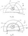
- Fig. 2 shows a cross-section of a flash lamp of this invention having an attenuating material.
- Fig. 3 shows a cross-section of another flash lamp of this invention having an attenuating material.
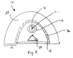
- Fig. 4 shows a cross-section of another flash lamp of this invention having an attenuating material.
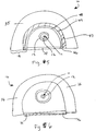
- Fig. 5 shows a cross-section of another flash lamp of this invention having an attenuating material.
- Fig. 6 shows a cross-section of another flash lamp of this invention having an attenuating material.
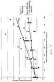
- Fig. 7 is a graph of the Equilibrium Water Content of a contact lens polymer as function of the radiation dose to the polymer for systems with and without attenuating materials of this invention.
- the radiation system of this invention comprises a high energy UV radiation source.
- UV radiation sources that can be used in the radiation system include discrete or continuous producing, incoherent lamps, such as flash lamps, arc lamps (continuous or non-continuous), deuterium lamps, or continuous wave light sources, e.g. xenon gas or mercury vapor light sources.
- the UV radiation sources are high energy, that is, they generate greater than 0.1 J/cm 2 per pulse for a flash lamp or 20 watts/cm 2 for a continuous radiation source, preferably of which at least 1 percent of the radiation is from 240 to 280nm.
- the presently preferred UV radiation source is a flash lamp which produces at least 1 J/cm 2 broad spectrum radiation (200 - 3000nm) per flash of which at least 10 mJ/cm 2 per flash is UV radiation.
- the preferred application is sterilization, in particular sterilization of contact lenses (target).
- the desired radiation is the germicidal radiation which includes the radiation from 240 to 280nm; with many references indicating that 254nm is the peak of the germicidal range; however, destruction to the contact lens polymer occurs upon exposure to the radiation below 320nm to about 100nm (non-ionizing UV radiation).
- EP-A-00301642.5 discloses that radiation at wavelengths less than 320nm are absorbed by the contact lens polymers and may cause chain scissions within the polymers. The most destructive radiation is from 180nm up to 240nm. (The term "up to" when used to describe a range means that the endpoint is not included within the range specified.) To prevent the destruction to polymers of the target, e.g. container or medical device by chain scissions or other mechanisms due to the UV radiation, this invention provides attenuating materials and ways of incorporating the attenuating materials into the radiation system to attenuate the undesirable wavelengths from at least a portion of the destructive radiation dose before the radiation reaches the target. EP-A-00301642.5 further discloses that the energy of the radiation (240 to 280nm) to the microorganism has to be at least 18 mJ/cm 2 for sterilization.
- Attenuate the radiation or a portion of the radiation from 180nm up to 240nm; or at least greater than 200nm up to 240nm. However, for some applications it may be more preferable to attenuate the radiation or a portion of the radiation from 180nm up to 250nm.
- the attenuation increases the ratio of the desired (e.g. germicidally-effective) radiation to the undesired (e.g. damaging) radiation reaching the target, e.g. polymer, container and/or product.
- the target e.g. polymer, container and/or product.
- Increasing the ratio of germicidally-effective radiation to damaging radiation makes it possible to increase the overall radiation dose, if necessary for sterility, and makes it easier to control the system when the threshold of damage to the polymer is far below the dose for sterility.
- the attenuating materials of this invention provide greater than a 30 percent reduction in the total undesired radiation, more preferably greater than a 60 percent reduction, and most preferably greater than a 90 percent reduction in the total undesired radiation which impinges upon the attenuating materials.
- the undesired radiation is from 100nm up to 240nm, or at least from 180nm up to 240nm, or at least greater than 200nm up to 240nm. It is preferred to attenuate at least a portion of all the wavelengths of radiation specified in the specified ranges.
- the attenuating materials will not attenuate all the wavelengths in a given range at a single percentage, so certain attenuating materials will be better suited for some applications than others, or mixtures of the attenuating materials can be used to achieve improved reductions at certain or all of the wavelengths in the range of undesired wavelengths.
- An example of a mixture is chloroform and absolute ethanol. It is preferred that the attenuating materials attenuate the undesired radiation, and that the attenuating materials direct the desired radiation toward the target.
- the attenuating materials can direct the desired radiation toward the target by transmitting and/or reflecting the desired radiation from the radiation source which impinges upon the attenuating material, and/or by re-emitting absorbed undesired radiation as radiation within the desired radiation.
- the attenuating materials can direct the desired radiation towards the target either directly or indirectly, that is, the desired radiation may impinge upon other apparatus before striking the target, e.g. reflectors, mirrors, fiber optics, or the like.
- the attenuating materials direct greater than 50 percent of the desired radiation, more preferably greater than 75 percent and most preferably greater than 90 percent of the desired radiation, which impinges upon the attenuating materials.
- the desired radiation is 240 to 280nm.
- the attenuating materials direct, e.g., transmit, reflect and/or re-emit, the desired radiation to the target can determine where the attenuating materials are positioned with respect to the radiation source and target.
- the attenuating materials are positioned with respect to the radiation source and target.
- at least a portion of all the wavelengths of the undesired radiation in the ranges specified is transmitted, reflected or emitted by the attenuating materials.
- the preferred materials are those that attenuate greater than 30 percent of the undesired radiation and direct greater than 50 percent of the desired radiation.
- the more preferred attenuating materials attenuate greater than 50 percent of the total radiation from 100 up to 240nm and direct greater than 90 percent of the total radiation from 240 to 280nm which impinges upon the attenuating materials whereby at least some portion of the radiation between 200 up to 240nm is attenuated, preferably greater than 30%, more preferably greater than 60%, most preferably greater than 90% of the radiation between 200 up to 240nm is attenuated.
- at least a portion of all the wavelengths of the undesired radiation in the ranges specified is attenuated, and at least a portion of all the wavelengths of the desired radiation in the ranges specified is directed.
- the attenuation materials preferably provide an attenuation ratio greater than 1.2, more preferably greater than 1.8, most preferably greater than 2.5.
- the attenuation ratio is defined as the percent of the desired radiation directed by the attenuation materials divided by the percent of the undesired radiation absorbed by the attenuation materials.
- the attenuation ratio of a reflector of lanthanum oxide would have an attenuation ratio of 3 (see Table 1).
- Attenuating materials can be liquids, solids, or gases.
- An example of an attenuating material which is a gas is ozone, e.g. 10 ppm ozone in air.
- Liquid attenuating materials include polyols, such as alkyl alcohols, more preferably propylene glycols having a weight average molecular weight from 200 to 1,000, and most preferably propylene glycols having a weight average molecular weight of 200.
- polyethylene glycols include PEG 200, PEG 400, PEG 600, from Aldrich Chemical Co.
- halogenated carbon compounds such as, fluorocarbons, chlorocarbons, chloroform, more preferably fully halogenated carbon compounds, because they are more stable, such as, freon, except for fluorinerts which are also more preferred although not fully halogenated.
- fluorinerts include FC-40, FC-43, FC-70, commercially available from 3M, available from Aldrich Chemical Company.
- the preferred fluorinerts have nitrogen within their compositions.
- Other liquid attenuating materials include organic carbonates, more preferably aliphatic carbonates, such as propylene carbonates.
- liquid attenuating materials include silicon compounds, such as sodium silicate, more preferably polysiloxane compounds such as polydimethylsiloxanes, most preferably hydride-terminated silicone oil. Mixtures of the above-described liquids can be used as the liquid attenuating-materials. The preferred mixtures are those of halogenated carbon compounds and organic carbonates, more preferably chloroform and propylene carbonate. Ways to incorporate the liquid attenuating materials into the radiation system to attenuate radiation will be described below.
- the liquid attenuating materials will need to be pumped through or around the radiation source or target of the radiation; therefore, it is preferred that the liquid attenuating materials have a viscosity from 1 to 1,000 cps, more preferably from 1 to 500 cps and most preferably from 1 to 100 cps.
- the easiest liquid attenuating materials to pump have a viscosity of from 1 to 10 cps.
- the liquid attenuating materials can be used in a suitable liquid carrier; preferably a non-ionic liquid, or they can comprise a solid attenuating material in a suitable liquid carrier to form a dispersion or colloid with the solid, for example 2-hydroxyethylmethacrylate (HEMA) or ethylene glycol dimethacrylate (EDGMA) in water.
- HEMA 2-hydroxyethylmethacrylate
- EDGMA ethylene glycol dimethacrylate
- FIG. 1 Examples of liquids which can be used as attenuating materials are shown in Figure 1.
- the curves in Figure 1 were generated by placing cuvettes having a 10 mm pathlength filled with the sample liquids into a spectrophotometer, and recording the light which passed through the samples.
- Liquid attenuating materials can be used in various locations to attenuate selected radiation.
- a first set of embodiments using liquid attenuating materials will be described in reference to Fig. 2.
- Fig. 2 shows a cross-section of a conventional flash lamp 10; although it is understood that other radiation sources described earlier can be used in the radiation system of this invention, such as arc lamps (continuous or non-continuous), deuterium lamps, or any other source which produces at least a portion of the radiation from 180 up to 240nm or greater than 200 up to 240nm, and at least a portion of the radiation from 240 to 280nm, and most preferably in a continuum between 100 and 400nm.
- arc lamps continuous or non-continuous
- deuterium lamps or any other source which produces at least a portion of the radiation from 180 up to 240nm or greater than 200 up to 240nm, and at least a portion of the radiation from 240 to 280nm, and most preferably in a continuum between 100 and
- the flash lamp 10 consists of a lamp 11 which consists of two electrodes (not shown) each connected to the end of a hollow lamp envelope 12.
- the lamp envelope 12 is made out of a strong transparent material which can withstand high temperatures and thermal shock such as glass, quartz or sapphire or the like. The lamp generates radiation when an arc is created between the electrical connectors.
- the lamp envelope 12 may be inside a flow tube 13 as shown.
- the flow tube 13 provides protection for the lamp envelope 12.
- cooling water is pumped in the passageway 16 formed between the lamp envelope 12 and the flow tube 13 to dissipate the heat generated by the lamp 11.
- one or more liquid attenuating materials can be used in place of the cooling water in the passageway 16 between the flow tube 13 and the lamp envelope 12 to both attenuate selected wavelengths and to cool the lamp 11.
- the attenuating materials can be pumped in the passageway 16 between the lamp envelope 12 and the flow tube 13.
- Attenuating materials pumped between the lamp envelope and the flow tube must be highly resistive, preferably greater than 1 megohm, more preferably greater than 10 megohms, most preferably greater than 18 megohms, because of the potential of a short circuit within the lamp.
- FIG. 2 Another embodiment of the invention is shown in Fig. 2.
- the flash lamp 10, in Fig. 3 is similar to the flash lamp shown in Fig. 2 and consists of a reflector 14, and a protective window 15 (similar elements are labeled with the same number in the figures).
- Passageways 28 and 29 may be added adjacent to the reflector 14 or the protective window 15 through which liquid attenuating materials may be added or pumped and used to attenuate selected wavelengths of the radiation.
- the passageways may be constructed of glass, quartz, sapphire or the like. Both passageways 28, 29 are shown in Fig. 3, but in alternative embodiments each passageway 28 or 29 may be used alone to hold an attenuating material to attenuate the undesired radiation.
- the sensitivity of the liquid attenuating materials to the radiation will determine the exposure amounts of the liquid attenuating materials to the radiation. If the liquid attenuating materials' ability to absorb or otherwise attenuate the radiation breaks down significantly after one exposure to the radiation, then those liquid attenuating materials can be continuously pumped through the passageways, exposed only once to the radiation, and then discarded.
- the liquid attenuating materials can be exposed to several flashes and then discarded, or exposed once to the radiation and mixed with a reservoir of the liquid attenuating material from which additional liquid attenuating material can be drawn and exposed, and this process can be repeated for an amount of time until it is determined that the ability of the liquid attenuating material in the reservoir to attenuate the radiation has been reduced to a point that the reservoir should be discarded and replaced with a fresh supply of liquid attenuating material.
- the attenuation ability of the liquid attenuating materials can be monitored using a spectrophotometer.
- composition of the passageways in which the liquid attenuating materials are held and the individual liquid attenuating material's ability to attenuate the undesired radiation will be factors to consider when determining the thickness of the passageways (wavelength pathlength) which hold the liquid attenuating materials.
- Solid attenuating materials include, but are not limited to, alkaline metal compounds (oxides and halides), heavy metal oxides (e.g. barium), divalent metal oxides (e.g. magnesium), and polyvalent metal oxides (e.g. ytterbium or aluminum).
- Solid attenuating materials can also be selected according to the following formula M a O b X c H d wherein M is a single metal or a mix of metals, preferably a rare earth metal, O is oxygen, X is a heteroatom such as sulfur, nitrogen and phosphorous or the like, and H is a halide, preferably fluorine, a is 1 to 20, preferably 1 to 12, b is 0 to 20, preferably 0 to 12, c is 0 to 20, preferably 0 to 12, and d is 0 to 20, preferably 0 to 12, with the proviso that at least b, c or d is at least 1.
- These materials need to be of sufficient purity such that the levels of impurities do not degrade the reflector performance.
- the materials are more than 99.9 % pure, more preferably more than 99.99 % pure.
- Examples of useful solid materials are listed in Table 1. Included in Table 1 are the mean percent reflectivities of the solid attenuating materials. The percent reflectivities were determined by packing a dry powder sample of solid material into a cuvette, and putting the cuvette into a spectrophotometer having an integrating sphere which measured the radiation reflected from the sample.
- the solid attenuating material is a metal oxide, such as calcium oxide (CaO) and hafnium oxide (HfO 2 ), lanthanum oxide(La 2 O 3 ), iron oxide (Fe 3 O 4 ), terbium oxide (Tb 4 O 7 ), praseodymium oxide (Pr 6 O 11 ), and barium titanate (BaTiO 3 ).
- a metal oxide such as calcium oxide (CaO) and hafnium oxide (HfO 2 ), lanthanum oxide(La 2 O 3 ), iron oxide (Fe 3 O 4 ), terbium oxide (Tb 4 O 7 ), praseodymium oxide (Pr 6 O 11 ), and barium titanate (BaTiO 3 ).
- An example of solid attenuating material for which a is 1, d is 2 and b and c are 0 is magnesium fluoride (MgF 2 ).
- solid attenuating materials include magnesium oxide (MgO), aluminum oxide (Al 2 O 3 ) barium oxide (BaO), barium titanate (BaTiO 3 ), holmium oxide (Ho 2 O 3 ), calcium oxide (CaO), lanthanum oxide (La 2 O 3 ), germanium oxide (GeO 2 ), tellurium oxide (TeO 2 ), europium oxide (Eu 2 O 3 ), erbium oxide (Er 2 O 3 ), neodymium oxide (Nd 2 O 3 ), samarium oxide (Sm 2 O 3 ), ytterbium oxide (Yb 2 O 3 ), yttrium oxide (Y 2 O 3 ), and dysprosium oxide (Dy 2 O 3 ).
- MgO magnesium oxide
- Al 2 O 3 aluminum oxide
- BaO barium oxide
- BaTiO 3 barium titanate
- Ho 2 O 3 holmium oxide
- CaO calcium oxide
- La 2 O 3 lanthanum oxide
- the preferred attenuating materials are magnesium oxide, erbium oxide, holmium oxide, samarium oxide, tellurium oxide, lanthanum oxide, yttrium oxide, and ytterbium oxide, and the most preferred are lanthanum oxide, yttrium oxide, and ytterbium oxide.
- the solid attenuating materials can be incorporated into the radiation source (e.g. a lamp envelope, protective window or flow tube) which prevents the damaging radiation from reaching the target, e.g. polymer, product and/or packaging, to be exposed.
- a radiation source include a pulsed light source (e.g. xenon gas) or a continuous wave light source (e.g. mercury vapor).
- the solid attenuating materials can be added to the feed stock used to make the glass (e.g. sapphire, quartz, glass, crystalline materials, and the like), as what is commonly referred to in the glass industry as a dopant, during the manufacture of the lamp envelope and/or the flow tube and/or protective window.
- the proper selection of dopants for the flow tube or the lamp envelope can increase the performance of the lamp by reducing thermal shock, solarization, fluorescence, phosphorescence, and/or can be used to reduce the undesirable radiation by absorption, or absorption and re-emission at desired or at least not undesired wavelengths. Attenuating materials which can absorb radiation at undesired wavelengths and re-emit at desired wavelengths are preferred.
- the attenuating materials can also be used to form a filter through which the radiation will pass prior to impinging upon the target which will attenuate the undesirable wavelengths before they contact the target, or the attenuating materials can be added to the packaging material.
- the Beer-Lambert equation quantifies the radiation absorption by a particular dopant or attenuating material:
- /I 0 ( ⁇ ) exp(- ⁇ ( ⁇ )cx) where I( ⁇ ) is the intensity of the attenuated radiation as a function of wavelength ( ⁇ ), I 0 ( ⁇ ) is the initial radiation intensity as a function of wavelength, ⁇ ( ⁇ ) is the molar absorptivity of the dopant (attenuation material) as a function of wavelength, c is the concentration of the dopant, and x is the path length (thickness of the material in which the dopant is present) through which the radiation passes.
- ⁇ ( ⁇ ) can be determined spectrophotometrically as described for generating the data in Table
- An alternative embodiment of the invention is to add the solid attenuating materials to other parts of the radiation source, e.g. as part of a reflector as described in reference to Figs. 4 and 5.
- Figure 4 is shown a cross-section of a flash lamp 10 similar to that shown in Fig. 2 (similar elements are labeled with the same number).
- Figure 4 shows an attenuating coating 36 as part of the reflector 14.
- the reflector 14 also consists of a reflector support 35.
- the attenuating coating 36 comprises an attenuating material.
- the attenuating coatings can be applied by painting, spraying, plasma coating, dipping, casting, conversion coating, gel coating, etching, chemical vapor depositing, sputtering, or chemical or mechanical bonding, e.g.
- the preferred method of applying the attenuating coatings is to paint or spray attenuating materials onto a reflector support.
- an aqueous or non-aqueous suspension is formed preferably comprising attenuating material and binder.
- Useful binders are polymeric, inorganic or sol-gels, more preferably inorganic or sol gel, and most preferably inorganic.
- the preferred suspension comprises 0.1 to 50 % binder, 0.1 to 99.9 % attenuating material, and 0.1 to 90 % carrier.
- the carrier is a liquid used to form a dilution of the attenuating materials and binder to apply the coating. Examples of useful carriers are water, alcohols, alkanes, freons, and the like, most preferably water.
- polymeric binders useful in making coatings comprising attenuating materials are polyvinyl alcohols, cyanoacrylates, acrylics, and silicones. Presently the polymeric binders are limited in their use, because they tend to degrade in the high energy UV radiation.
- inorganic binders useful in making coatings comprising attenuating materials are sodium silicate, low-temperature sintered glasses, alkali oxide silicates, such as sodium, potassium and lithium silicates.
- sol gel binder precursors useful in making coatings comprising attenuating materials are aluminum tert butoxide, sodium silicate, tetraethylorthosilicate (TEOS), metal isopropoxides, dysprosium ethylhexano-diisopropoxide in isopropanol, dysprosium 2-ethylhexanoate in hexane, dysprosium isopropoxide in toluene-isopropanol, dysprosium 2-methoxyethoxide in 2-methoxyethanol, erbium ethylhexano-diisopropoxide in isopropanol, erbium 2-ethylhexanoate in hexane, erbium isopropoxide in toluene-isopropanol, holmium ethylhexano-diisopropoxide in isopropanol, holmium
- the preferred sol gel precursors are erbium ethylhexano-diisopropoxide in isopropanol, erbium 2-ethylhexanoate in hexane, erbium isopropoxide in toluene-isopropanol, holmium ethylhexano-diisopropoxide in isopropanol, holmium isopropoxide in toluene-isopropanol, holmium 2-methoxyethoxide in 2-methoxyethanol, lanthanum acetate, lanthanum 2-ethylhexanoate in hexane, lanthanum isopropoxide, lanthanum 2-methoxyethoxide in 2-methoxyethanol, magnesium ethoxide in ethanol, magnesium methoxide in methanol, magnesium 2-methoxyethoxide in 2-methoxyethanol, samarium ethy
- the more preferred sol gel precursors are lanthanum acetate, lanthanum 2-ethylhexanoate in hexane, lanthanum isopropoxide, lanthanum 2-methoxyethoxide in 2-methoxyethanol, ytterbium isopropoxide in toluene-isopropanol, ytterbium 2-methoxyethoxide in 2-methoxyethanol, yttrium ethylhexano-diisopropoxide in toluene-isopropanol, yttrium ethylhexano-monoisopropoxide in toluene-isopropanol.
- binders can be used alone as the attenuating materials, particularly the sol gels which can be applied as described above in a suspension or sintered to form a solid attenuating material.
- binders which can be used alone as the attenuating materials include dysprosium isopropoxide, dysprosium ethylhexano-diisopropoxide in isopropanol, dysprosium 2-ethylhexanoate in hexane, dysprosium isopropoxide in toluene-isopropanol, dysprosium 2-methoxyethoxide in 2-methoxyethanol, erbium ethylhexano-diisopropoxide in isopropanol, erbium 2-ethylhexanoate in hexane, erbium isopropoxide in toluene-isopropanol, holmium ethylhexano-
- the attenuating materials disclosed herein can be used in thin layers and/or multiple layers of different attenuating materials similar to dichroic filters also referred to dielectric filters; however, the attenuating materials disclosed herein do not work by the same mechanism as a dielectric filter, that is, they do not rely upon a structure comprised of alternating materials with differing indices of refraction.
- the materials of this invention use absorption mechanisms to selectively attenuate the radiation.
- the attenuating coatings are preferably applied to form a coating having a thickness from 0.1 to 2500 microns, more preferably a thickness from 0.5 to 2500 microns. (A coating greater than 2500 microns is considered a block of the material).
- the coatings are preferably applied in multiple layers of the same attenuating material(s), preferably in the same coating composition.
- the coating of the attenuating materials on a reflector reduces the undesired radiation which impinges upon the attenuating materials two times: once on the radiation's way to the reflector and once after the radiation is reflected off the reflector, which is a factor to consider when formulating the attenuating materials to be applied to the reflector, and when estimating the useful life of the attenuating materials (particularly if liquid attenuating materials are in a passageway in front of the reflector). Also, depending upon the shape of the one or more reflectors of the radiation source, much of the radiation will be reflected off of the reflectors multiple times before it reaches the target.
- the reflector 14 which comprises the coating 36 of the attenuating material can comprise a reflective material, or a non-reflective or reflective reflector support 35 onto which a reflective coating (which may be a film or foil) is held.
- a reflective material is metal.
- An example of a reflective reflector support 35 is a solid polished aluminum, which is thick enough to hold its shape, and is bolted or otherwise mounted into place around the lamp 11.
- reflective materials which can be used alone as the reflector support 35 include: formed solids of barium sulfate, aluminum oxide, magnesium fluoride, and magnesium oxide.
- the formed solids can be formed by combining the reflective materials with metal oxides or powdered glass and sintering them to form a reflective support, or by combining the reflective materials with binders and forming a solid either in the shape of the support or machining the reflector out of the resulting formed solid.
- coatings of reflective material which can be applied, or otherwise attached to a reflective or non-reflective reflector support 35 include: magnesium oxide, magnesium fluoride, barium sulfate and aluminum oxide, including thin sheets of aluminum, aluminum oxide, magnesium fluoride, barium sulfate and magnesium oxide which can be attached to a reflector support 35. These coatings or films can be formed by sintering the reflective materials with glass compositions, or forming films of the reflective materials with binders. Examples of materials which can be used as a non-reflective reflector support 35 include: wood, polymers, metals and ceramics.
- the reflective coatings of the reflector support 35 can be coated by painting, plasma coating, spraying, dipping, casting, conversion coating, gel coating, etching, chemical vapor deposition, sputtering, or mechanical or chemical bonding of a thin film or foil of the reflective material to a reflective or non-reflective support.
- the preferred method of applying the reflective materials which are part of the reflector 14 is to paint or spray them onto a reflector support 35.
- an aqueous or non-aqueous suspension is formed with a binder.
- the preferred binders are polymeric, inorganic or a sol-gel, more preferred inorganic or sol gels.
- polymeric binders are polyvinyl alcohols, cyanoacrylates, acrylics, and silicones. Presently the polymeric binders are the least preferred, because it is believed that the UV radiation will cause them to degrade.
- inorganic binders are sodium silicate, low-temperature sintered glasses, alkali oxide silicates, such as sodium, potassium and lithium silicates. Examples of sol gel precursors are listed above for the attenuating materials.
- An example of an attenuating coating composition is 1 part sodium silicate (binder), 10 parts lanthanum oxide (attenuating material) and 10 parts water (carrier). 10 layers of this suspension were sprayed onto a reflector which comprised an aluminum substrate (reflector support) having a barium sulfate coating (reflective material).
- the barium sulfate coating was made by spraying 20 layers of a composition comprising 1 part sodium silicate (binder), 10 parts barium sulfate (reflective material) and 10 parts water (carrier) onto the aluminum substrate. Each coating was air dried between coatings.
- the reflective materials and attenuating materials and optional binders can be combined and applied to a reflective or non-reflective reflector support 35 in a single coating which reflects the desired, e.g. germicidally-effective radiation, and attenuates the undesired radiation.
- the attenuating materials may act as the binder for the reflective material, therefore eliminating the need for a binder in the composition. Examples of materials which can act as the binder and attenuating material are dysprosium isopropoxide, polysiloxanes, and all the sol gels, listed above.
- the attenuating material and reflective material can be sintered to form a reflector coating 36 composition having radiation attenuating properties.
- An example of a material which can be used as a sintering material is a low melting glass composition, to which the attenuating material and reflective materials can be added. These coatings preferably have a thickness between 0.1 and 2500 microns.
- a reflector 14 similar to the one shown in Fig.1, can be formed out of a formed solid comprising attenuating materials, reflective material, and optional binders.
- the composition is formed in the shape of a reflector 14 or the reflector 14 can be machined out of the formed solid which comprises the reflector materials, attenuating materials and optional binders.
- the attenuating materials can be combined with metal oxides or powdered glass and reflective materials and sintered to form a reflector 14 similar to the one shown in Fig. 1 which has attenuating and reflective properties.
- the just-described formed solids preferably have a thickness greater than 2500 microns.
- the preferred attenuating materials are those that absorb the undesired radiation from 100 up to 240nm, and reflect the desired radiation from 240 to 280nm which can be used alone or with optional binders and/or additives to form the reflectors in any of the embodiments described above.
- Examples of these attenuating materials are lanthanum oxide, yttrium oxide and ytterbium oxide. Using these reflective/attenuating materials to make a reflector, or a coating for a reflector support is the most preferred embodiment of the invention.
- a reflective blocking element can be used so that only reflected radiation from which the undesired radiation has been attenuated can impinge on the target.
- the reflective blocking element 39 is shown in Figure 4.
- the reflective blocking element preferably has a simple geometric form, more preferably an optically concentrating form, and most preferably an integral form of the reflecting optics. Examples of useful shapes are a triangle (shown in Fig. 4) and a half circle.
- the reflective blocking element can comprise any of the reflector compositions described within this application, and may or may not be made with attenuating materials or a coating of attenuating materials.
- the reflective blocking element comprises an attenuating material, preferably either a liquid or solid attenuating material. It is preferred that the reflective blocking element has a diffuse reflective surface.
- the blocking element is sized to occlude any direct radiation from the radiation source to the target.
- Fig. 5 shows an alternative embodiment of this invention.
- the reflector 14 comprises a reflector support 35, a material layer 47 and a transparent support 46.
- the transparent support 46 is transparent to at least a portion of the radiation which impinges upon it.
- the reflector support 35 can comprise any of the combinations of reflective or non-reflective supports, or coatings on the supports as described above.
- the material layer 47 comprises one or more solid attenuating materials, or can be any of the compositions comprising attenuating materials as described for Fig. 4; however, this embodiment is particularly suited for solid attenuating materials that will not stay in place without the presence of the transparent support 46, such as a packed powder.
- the material layer 47 can comprise an attenuating material alone, a mixture of reflective materials and attenuating materials, or an attenuating material that also reflects the desired radiation as described in reference to Fig. 4, except that the material layer 47 can be a packed powder. If the reflector comprises separate attenuating materials and reflective materials, it is preferred that the attenuating materials are located between the reflective materials and the radiation source, so that the undesirable radiation is attenuated by the attenuating materials before the desired, e.g. germicidally-effective, radiation is reflected by the reflective materials towards the target.
- the material layer 47 preferably has a thickness from 0.1 to 2500 microns.
- the transparent support 46 can be completely transparent to most or all of the wavelengths which impinge upon it, or the transparent support 46 can comprise a solid attenuating material which attenuates one or more of the undesired wavelengths of the radiation. Alternatively, the transparent support 46 can have a passageway through which liquid attenuating materials are pumped or otherwise held within (not shown).
- the transparent support 46 preferably comprises the glass, quartz or sapphire materials described above for the flow tube 13, lamp envelope 12, and/or protective window 15.
- the solid attenuating materials can be added to the transparent support 46 as a dopant in feed stock used to form the transparent support, or attenuating materials can be applied as a coating onto either or both sides of the transparent support 46.
- the attenuating materials are applied to one side of the transparent support 46, preferably it is the side 49 furthest from the lamp.
- the methods for applying the coating are as described above for earlier embodiments.
- reflective materials can be applied as a coating to the side 49 of the transparent support 46 furthest from the lamp, and the solid attenuating materials can be applied onto the other side 48 of the transparent support, if desired.
- the material layer 47 and the reflector support 35 might not be necessary.
- the coatings on the transparent support 46 will preferably be from 0.1 to 2500 microns.
- the preferred attenuating material for the material layer 47 used in combination with the transparent support 46 is a packed layer of powder consisting of the preferred solid attenuating materials listed above. As listed above, the most preferred solid attenuating materials are lanthanum oxide, yttrium oxide or ytterbium oxide or mixtures of these powders.
- reflective materials either coating, solid blocks or dry powder under a coating of a solid attenuating material.
- the preferred combinations of reflective materials and attenuating materials in the preferred embodiments are barium sulfate (reflective material) and lanthanum oxide (attenuating material); or magnesium fluoride (reflective material) and yttrium oxide (attenuating material), or magnesium oxide (reflective material) and ytterbium oxide (attenuating material), or aluminum oxide (reflective material) and lanthanum oxide (attenuating material), or different combinations of the reflective materials and attenuating materials, or mixtures of individual reflective materials and mixtures of individual attenuating materials.
- the preferred reflectors are diffuse reflectors and/or elliptically-shaped reflectors which are disclosed and described in copending European patent application claiming priority from USSN 60/143 608 (Attorney's ref: P025028EP).
- the preferred lamp system comprises two lamps each having a shaped reflector, preferably an elliptically-shaped reflector, within which is a target volume (the volume occupied by the target container and/or product) having an optimized amount of space or minimal space between the target and the reflectors during the exposure of the target to radiation.
- a target volume the volume occupied by the target container and/or product
- the space adjacent to the target area or volume allows radiation to pass by the target without passing through the target. Therefore, particularly for a multiple lamp and/or reflector radiation system, the space should be minimized.
- the diffuse reflectors provide uniform energy to the target area or volume.
- FIG. 6 shows this embodiment wherein a removable solid attenuating material is a film 56 which is mounted adjacent to the protective window 15 of a flash lamp 10.
- the removable solid attenuating material 56 can comprise any of the above listed solid attenuating materials which are either combined with a binder to form a removable solid attenuating material 56, or the solid attenuating materials can be sintered with optional glass or metal oxides to form a solid, or a dry powder can be packed into a glass support.
- These removable solid materials 56 like the coatings, and reflectors made for the embodiments described above are very durable.
- the removable solid attenuating material 56 can be a block or plate.
- the block or plate preferably has a thickness of from 100 to 2500 microns.
- the removable solid attenuating material 56 is a sheet or film preferably comprising a polymeric material, e.g. polyamides (nylons), or polyolefins, such as polypropylene, preferably nylons such as nylon-6 and nylon-6,6.
- the sheet or the film may only have temporary effectiveness and may require replacement with a new or different piece or area of the removable solid attenuating material.
- the removable solid attenuating material 56 is a film which can be on rollers (not shown) which advances an exposed area of the removable solid attenuating material 56 to a never-before-exposed portion after a specified amount of exposure to the UV radiation source.
- the film preferably has a thickness of from 10 to 100 microns.
- a product to be exposed to the UV radiation is housed in a container
- another alternative is to add the attenuating materials to the container or to form the container out of attenuating materials, or to add the attenuating materials to the product, or to the solution in which the product is stored, e.g. contact lens solutions.
- Any of the above listed attenuating materials, preferably the solid attenuating materials, can be applied to the container by all the methods described above e.g. coating, dipping, etc., or the attenuating materials can be included in the container formulation used to make the container, or the materials for the container can be selected based on their ability to attenuate the undesired radiation and transmit the desired radiation.
- a container is used to house a contact lens to be sterilized.
- the container comprises a bowl and a lidstock.
- the lidstock can comprise a nylon layer and/or attenuating materials, such as lanthanum oxide, or adipic acid (hexanedioic acid) and various adipates, barium adipate, calcium adipate, magnesium adipate, disodium adipate or carboxylic acids, can be added to the molten polypropylene or polystyrene before injection molding the lidstock or the bowl.
- adipic acid hexanedioic acid
- adipates barium adipate, calcium adipate, magnesium adipate, disodium adipate or carboxylic acids
- Attenuating materials such as polyamides (nylons) can be co-injected with the polypropylene to form a multi-layered bowl that filters out the damaging radiation.
- Attenuating materials e.g. sol gels
- Lanthanum oxide is an example of an attenuating material which would be useful for this purpose.
- sol gel precursors useful in the lidstock include: Barium hexafluoroacetylacetonate, Barium (2,2,6,6-tetramethyl-3,5-heptanedionate), Lanthanum acetylacetonate hydrate, Lanthanum (2,2,6,6-tetramethyl-3,5-heptanedionate), Magnesium acetylacetonate dihydrate, Magnesium (2,2,6,6-tetramethyl-3,5-heptanedionate), Ytterbium acetylacetonate, Ytterbium hexafluoroacetylacetonate, Ytterbium (2,2,6,6-tetramethyl-3,5-heptanedionate), Yttrium acetylacetonate, Yttrium hexafluoroacetylacetonate, and Yttrium (2,2,6,6-tetramethyl-3,5-heptane
- the preferred attenuating materials are those that attenuate the undesired radiation and reflect, transmit or re-emit the desired radiation and have a sharp transition between the absorption of the undesired radiation and reflection, transmission or re-emission of the desired radiation. It is preferred that the change in % reflectivity/nm is greater than 2, more preferably greater than 3, most preferably greater than 4 in area of the radiation spectrum where the transition from desirable wavelengths of radiation to undesirable wavelengths of radiation is located.
- the sharp transition preferably takes place from 230 to 250nm, more preferably from 235 to 245nm, and most preferably from 239 to 240nm.
- Combinations of the above described embodiments are contemplated by this invention to produce an additive effect on reducing the undesired radiation, and increasing the ratio of the desired to the undesired radiation.
- the most preferred embodiments are the ones which use durable attenuating materials that do not have to be monitored or changed often. It is preferred that the attenuating materials can survive the application of 100 pulses at 3 J/cm 2 , more preferred greater than 10,000 pulses, and most preferably greater than 1,000,000 pulses at 3 J/cm 2 total radiation before undergoing a significant change in their ability to attenuate the undesired radiation.
- the preferred embodiments are to add solid attenuating materials to the lamp envelope and/or flow tube around the lamp envelope, or to add the attenuating materials as a coating to the reflector.
- Acuvue® (Etafilcon A) contact lenses each in polypropylene bowls with 500 ⁇ l of borate buffered saline solution, and a clear lidstock heatsealed to the bowl were placed six at a time into the cavity of a PurePulse bright light system.
- the lenses in the containers were subjected to 4 flashes, from two xenon flash lamps flashing simultaneously, to provide about 12 J/cm 2 radiation from 200-3000nm of which about 850mJ/cm 2 was radiation from 240 to 280nm.
- the contact lenses were tested for water content both by refractive index and GRAVIMETRIC methods. The modulus and base curve were also measured. The measurements are in Table 2.
- Acuvue® contact lenses packaged as described above were treated as described above, except that a piece of 12 ⁇ m thick nylon film was placed beneath the containers on the bowl side of the containers.
- This example shows that the nylon attenuates the undesired radiation and partially protects the contact lens polymer from damage.
- Acuvue® (Etafilcon A) contact lenses each in polypropylene bowls with 500 ⁇ l of borate buffered saline solution, and a clear lidstock heatsealed to the bowl were placed into the cavity of a PurePulse bright light system.
- the lenses in the containers were subjected to various amounts of energy provided by two xenon flash lamps flashing simultaneously.
- the water content of the bowl side of the contact lenses was measured by the Abbe method after treatment at different energy levels. (Each point on the graph represents the average measurement for ten contact lenses.) These measurements are plotted in Figure 7.
- Acuvue® contact lenses packaged as described above were treated as described above, except that instead of using the specular polished aluminum PurePulse reflectors in the cavity, the specular reflectors were coated with 30 coats of barium sulfate and 10 coats of lanthanum oxide over the barium sulfate.
- the coating materials were spray coated at room temperature and dried between the application of each coat.
- the barium sulfate coating consisted of a 1:1:0.1 weight ratio of barium sulfate, water and sodium silicate.
- the lanthanum oxide coating consisted of a 1:1:0.1 weight ratio of lanthanum oxide, water and sodium silicate.
- Figure 7 shows that the attenuating coating on the reflectors protects the contact lenses from damage, which is evidenced by the decreased change in equilibrium water content for the contact lenses when treated with a system having attenuating materials in the reflectors as compared to the system without the attenuating material in the reflectors.
Abstract
Description
| Attenuating Materials | |||||||
| Observed Visual | %R Mean | %R Std Dev | %R Mean | %R Std Dev | %R Mean | %R Std Dev | |
| Material | Color | 200-400 | 200-400 | 240-280 | 240-280 | 200-240 | 200-240 |
| Barium Titanate | Beige | 18.55 | 10.11 | 14.42 | 0.27 | 21.44 | 9.04 |
| Cerium Oxide | Beige | 62.69 | 26.63 | 55.84 | 18.08 | 23.08 | 11.18 |
| Erbium Oxide | Pink | 62.69 | 26.63 | 55.84 | 18.08 | 23.08 | 11.18 |
| Europium Oxide | White | 54.79 | 34.3 | 45.1 | 1.26 | 23.78 | 10.73 |
| Germanium Dioxide | White | 84.13 | 21.32 | 72.83 | 10.51 | 50.72 | 14.64 |
| Hafnium Oxide | Beige | 32.26 | 7.49 | 25.83 | 0.51 | 31.04 | 9.69 |
| Holmium Oxide | Pink | 66.75 | 27.37 | 67.18 | 20.46 | 20.88 | 9.31 |
| Lanthanum Oxide | White | 82.99 | 28.39 | 88.23 | 11.97 | 29.49 | 12.36 |
| Magnesium Oxide | White | 97.27 | 14.21 | 101.44 | 0.52 | 19.68 | 24.49 |
| Praseodymium Oxide | Black | 13.67 | 5.59 | 12.13 | 0.33 | 20.7 | 9.49 |
| Samarium Oxide | L. Yellow | 68.84 | 27.62 | 51.32 | 23.08 | 27.58 | 6.59 |
| Terbium Oxide | Brown | 13.11 | 6.09 | 11.55 | 0.58 | 21.15 | 9.99 |
| Titanium Dioxide | White | 14.92 | 5.17 | 13.12 | 0.28 | 20.75 | 9.14 |
| Ytterbium Oxide | White | 70.72 | 33.16 | 45.8 | 26.02 | 23.2 | 11.84 |
| Yttrium Oxide | White | 85.81 | 24.14 | 89.38 | 6.51 | 41.14 | 15.4 |
| Zinc Oxide | White | 15.85 | 13.39 | 10.99 | 0.35 | 20.72 | 11.36 |
| CHARACTERISTICS | UNTREATED LENSES | TREATED LENSES | TREATED LENSES W/ATTENUATING MATERIAL |
| DOSE (mJ/cm2 @240 to 280nm) | NONE | 850 | 850 |
| NYLON FILM | NO | NO | YES |
| BASE CURVE(mm) | 8.82 | 8.79 | 8.82 |
| MODULUS (psi) | 42.3 | 36.3 | 40.2 |
| WATER (%) RI | 58.4 | 59.5 | 58.9 |
| WATER (%) GRAV | 59:5 | 60.2 | 59.6 |
| Observed Visual | %R Mean | %R Std Dev | %R Mean | %R Std Dev | %R Mean | %R Std Dev | |
| Material | Color | 200-400 | 200-400 | 240-280 | 240-280 | 200-240 | 200-240 |
| Praseodymium Oxide | Black | 13.67 | 5.59 | 12.13 | 0.33 | 20.7 | 9.49 |
| Titanium Dioxide | White | 14.92 | 5.17 | 13.12 | 0.28 | 20.75 | 9.14 |
| Zinc Oxide | White | 15.85 | 13.39 | 10.99 | 0.35 | 20.72 | 11.36 |
Claims (30)
- A high energy radiation system comprising a UV radiation source, wherein said apparatus comprises a selectively attenuating material which increases the ratio of desired to undesired radiation to reduce the radiation damage to a target by selectively attenuating at least 30 percent of the radiation from greater than 200nm up to 240nm which impinges upon said attenuating material, and directs greater than 50 percent of the radiation from 240nm to 280nm which impinges upon said attenuating material.
- The system of claim 1, wherein said selectively attenuated radiation is from 100nm up to 240nm, preferably from 180nm up to 240nm.
- The system of claim 1 or claim 2, wherein said system selectively attenuates at least 60 percent, preferably at least 90%, of the radiation from 180nm up to 240nm, more preferably greater than 90 percent of the radiation greater than 200nm up to 240 nm.
- The system of any one of claims 1 to 3, wherein said system directs greater than 75 percent, preferably greater than 90 percent, of the radiation from 240nm to 280nm.
- The system of any one of claims 1 to 4, wherein said attenuating material has an attenuation ratio of 1.2, preferably of 1.8.
- The system of any one of claims 1 to 5, wherein said attenuating material comprises a gas, a liquid or a solid.
- The system of claim 6, wherein said attenuating material is a liquid which is a polyol, a halogenated carbon compound, an organic carbonate, a silicon compound, a mixture of said liquids, or a solid attenuating material in a liquid carrier, and wherein said attenuating material is preferably an alkyl alcohol, a propylene glycol having a weight average molecular weight from 200 to 1,000, a fluorocarbon, a chlorocarbon, chloroform, a fully halogenated carbon compound, freon, a fluorinert, a fluorinert having nitrogen within its composition, an aliphatic carbonate, a propylene carbonate, sodium silicate, a polysiloxane compound, a polydimethylsiloxane, a hydride-terminated silicone oil or a mixtures of said liquids.
- The system of claim 7, wherein said liquid comprises chloroform and propylene carbonate.
- The system of claim 6 or claim 7, wherein the location of said liquid attenuating material is between a lamp envelope and a flow tube, between a flow tube and a protective window, within a passageway adjacent a reflector, within a passageway adjacent a protective window, or within a passageway located between a target and said radiation source.
- The system of claim 6, wherein said attenuating material is a solid material which is more than 99.9% pure.
- The system of claim 6 or claim 10, wherein said attenuating material is a solid which is an alkaline metal compound, a heavy metal oxide, a divalent metal oxide, a polyvalent metal oxide, a rare earth metal oxide, a rare earth metal halide, or a metallic combination oxide.
- The system of claim 11, wherein said solid: comprises MaObXcHd wherein M is a single metal or a mix of metals, O is oxygen, X is a heteroatom, H is a halide, a is 1 to 20, b is 0 to 20, c is 0 to 20 and d is 0 to 20, with the proviso that at least b, c or d is at least 1; preferably comprises calcium oxide, hafnium oxide, lanthanum oxide, iron oxide, terbium oxide, praseodymium oxide, barium titanate, magnesium fluoride, magnesium oxide, aluminium oxide, barium oxide, holmium oxide, germanium oxide, tellurium oxide, europium oxide, erbium oxide, neodymium oxide, samarium oxide, ytterbium oxide, yttrium oxide or dysprosium oxide; more preferably comprises magnesium oxide, erbium oxide, holmium oxide, samarium oxide, tellurium oxide, lanthanum oxide, yttrium oxide or ytterbium oxide; and most preferably comprises lanthanum oxide, yttrium oxide or ytterbium oxide.
- The system of any one of claims 10 to 12, wherein said attenuating material is a solid attenuating material incorporated as a dopant or coating into said system in a lamp envelope, protective window, flow tube, reflector, passageway, transparent support, blocking element or removable solid material.
- The system of claim 13, wherein said coating has been applied by painting, spraying, plasma coating, dipping, casting, conversion coating, gel coating, etching, chemical vapor depositing, sputtering or chemical or mechanical bonding.
- The system of claim 10, wherein said solid attenuating material comprises a polyvinyl alcohol, a cyanoacrylate, an acrylic or a silicone, such as sodium silicate, a low-temperature sintered glass, an alkali oxide silicate, a sodium, potassium or lithium silicate, a sol gel binder precursor, aluminium tert butoxide, sodium silicate, tetraethylorthosilicate (TEOS), a metal isopropoxide, dysprosium ethylhexano-diisopropoxide in isopropanol, dysprosium 2-ethylhexanoate in hexane, dysprosium isopropoxide in toluene-isopropanol, dysprosium-2-methoxyethoxide in 2-methoxyethanol, erbium ethylhexano-diisopropoxide in isopropanol, erbium 2-ethylhexanoate in hexane, erbium isopropoxide in toluene-isopropanol, holmium ethylhexano-diisopropoxide in isopropanol, holmium isopropoxide in toluene-isopropanol, holmium 2-methoxyethoxide in 2-methoxyethanol, lanthanum acetate, lanthanum 2-ethylhexanoate in hexane, lanthanum isopropoxide, lanthanum-2-methoxyethoxide in 2-methoxyethanol, magnesium ethoxide in ethanol, magnesium methoxide in methanol, magnesium 2-methoxyethoxide in 2-methoxyethanol, neodymium ethylhexano-diisopropoxide in isopranol, neodymium 2-ethylhexanoate in hexane, neodymium isopropoxide in toluene-isopropanol, neodymium 2-methoxyethoxide in 2-methoxyethanol, samarium ethylhexano-monoisopropoxide in toluene-isopropanol, samarium 2-ethylhexanoate in hexane, samarium isopropoxide in toluene-isopropanol, samarium 2-methoxyethoxide in 2-methoxyethanol, ytterbium isopropoxide in toluene-isopropanol, ytterbium 2-methoxyethoxide in 2-methoxyethanol, yttrium ethylhexano-diisopropoxide in toluene-isopropanol or yttrium ethylhexano-monoisopropoxide in toluene-isopropanol.
- The system of claim 13, wherein the thickness of the attenuating coating is from 0.1 to 2500 microns.
- The system of any one of claims 9 to 16, wherein said reflector further comprises a polished aluminium, barium sulfate, aluminium oxide, magnesium fluoride, magnesium oxide or, preferably, a mixture of barium sulfate and lanthanum oxide reflective material.
- The system of any one of claims 1 to 17, wherein the reflector machined out of the formed solid which comprises the reflector materials, and attenuating materials.
- The system of claim 17 or claim 18, wherein said attenuating material is lanthanum oxide, yttrium oxide or ytterbium oxide.
- The system of any one of claims 1 to 19 further comprising a blocking element.
- The system of claim 20 wherein said blocking element comprises said attenuating material, and has a diffuse reflective surface.
- The system of any one of claims 1 to 21 wherein no direct radiation from said radiation source impinges a target.
- The system of any one of claims 1 to 22 further comprising at least one reflector for said radiation source, wherein said reflector is a diffuse reflector having an elliptical shape.
- The system of any one of claims 1 to 23 further comprising a removable solid material comprising said selectively attenuated material, said solid material being located between the radiation source and the target.
- The system of claim 24 wherein said removable solid material has the form of a film, block, plate or powder packed into a support.
- The system of claim 25 wherein said film comprises a polymeric polyamide or polyolefin material.
- The system of any one of claims 1 to 26 wherein said system further comprises a target wherein said target comprises said attenuating material.
- The system of claim 27 wherein said target comprises nylon, lanthanum oxide, adipic acid, barium adipate, calcium adipate, magnesium adipate, disodium adipate, a carboxylic acid or a sol gel precursor or wherein said target further comprises a container and a product, wherein said container comprises barium hexafluoroacetylacetonate, barium 2,2,6,6-tetramethyl-3,5-heptanedionate, lanthanum acetylacetonate hydrate, lanthanum 2,2,6,6-tetramethyl-3,5-heptanedionate, magnesium acetylacetonate dihydrate, magnesium 2,2,6,6-tetramethyl-3,5-heptanedionate, ytterbium acetylacetonate, ytterbium hexafluoroacetylacetonate, ytterbium 2,2,6,6-tetramethyl-3,5-heptanedionate, yttrium acetylacetonate, yttrium hexafluoroacetylacetonate or yttrium 2,2,6,6-tetramethyl-3,5-heptanedionate.
- The system of any one of claims 1 to 28 wherein said attenuating material undergoes a change in % reflectivity/nm greater than 2 between from 230 to 250 nm, preferably greater than 3 between from 235 to 245nm.
- A high energy radiation system comprising a UV radiation source, wherein said apparatus comprises a selectively attenuating material which increases the ratio of desired to undesired radiation to reduce the radiation damage to a target by selectively attenuating at least 30 percent of the radiation from greater than 200nm up to 250nm which impinges upon said attenuating material, and directs greater than 50 percent of the radiation from 250nm to 280nm which impinges upon said attenuating material.
Applications Claiming Priority (4)
| Application Number | Priority Date | Filing Date | Title |
|---|---|---|---|
| US14360799P | 1999-07-13 | 1999-07-13 | |
| US143607P | 1999-07-13 | ||
| US09/515,190 US6465799B1 (en) | 1999-03-01 | 2000-02-29 | UV radiation system having materials for selectively attenuating radiation |
| US515190 | 2000-02-29 |
Publications (3)
| Publication Number | Publication Date |
|---|---|
| EP1069444A2 true EP1069444A2 (en) | 2001-01-17 |
| EP1069444A3 EP1069444A3 (en) | 2003-04-09 |
| EP1069444B1 EP1069444B1 (en) | 2006-03-08 |
Family
ID=26841229
Family Applications (1)
| Application Number | Title | Priority Date | Filing Date |
|---|---|---|---|
| EP00305903A Expired - Lifetime EP1069444B1 (en) | 1999-07-13 | 2000-07-12 | UV radiation system having materials for selectively attenuating radiation |
Country Status (12)
| Country | Link |
|---|---|
| US (1) | US6465799B1 (en) |
| EP (1) | EP1069444B1 (en) |
| JP (1) | JP4526665B2 (en) |
| KR (1) | KR101173932B1 (en) |
| CN (1) | CN1222322C (en) |
| AU (1) | AU4718200A (en) |
| BR (1) | BRPI0003325B8 (en) |
| CA (1) | CA2314039C (en) |
| DE (1) | DE60026458T2 (en) |
| HK (1) | HK1032267A1 (en) |
| SG (1) | SG86417A1 (en) |
| TW (1) | TW484142B (en) |
Cited By (3)
| Publication number | Priority date | Publication date | Assignee | Title |
|---|---|---|---|---|
| EP2485038A1 (en) * | 2005-08-31 | 2012-08-08 | Ultraviolet Sciences, Inc. | Ultraviolet light treatment chamber |
| ES2393881A1 (en) * | 2010-11-26 | 2012-12-28 | Consejo Superior De Investigaciones Científicas (Csic) | Narrow band filters centered in the extreme ultraviolet. (Machine-translation by Google Translate, not legally binding) |
| US9808544B2 (en) | 2005-08-31 | 2017-11-07 | Ultraviolet Sciences, Inc. | Ultraviolet light treatment chamber |
Families Citing this family (40)
| Publication number | Priority date | Publication date | Assignee | Title |
|---|---|---|---|---|
| CA2299691C (en) * | 1999-03-01 | 2011-07-12 | Johnson & Johnson Vision Care, Inc. | Package for medical device |
| SG93245A1 (en) * | 1999-07-13 | 2002-12-17 | Johnson & Johnson Vision Care | Reflectors for uv radiation source |
| DE60116561T2 (en) * | 2000-12-22 | 2006-11-09 | Koninklijke Philips Electronics N.V. | Apparatus for radiation treatment with a homogeneous UVB distribution |
| JP4790982B2 (en) * | 2001-06-15 | 2011-10-12 | ユーブイ−ソルーションズ・エルエルシー | Method and apparatus for sterilizing or disinfecting an area through a bandage |
| KR100854589B1 (en) * | 2002-03-26 | 2008-08-27 | 이세형 | Shoes Socks and Method for Producing the Same |
| US7152970B2 (en) * | 2003-03-12 | 2006-12-26 | Konica Minolta Holdings, Inc. | Image forming apparatus having a plurality of printing heads |
| DE10321149A1 (en) * | 2003-05-12 | 2004-12-02 | Bayer Materialscience Ag | Ytterbium (III) acetylacetonate as a catalyst for the production of aliphatic oligocarbonate polyols |
| WO2005077076A2 (en) * | 2004-02-11 | 2005-08-25 | Barry Ressler | System and method for product sterilization using uv light source |
| US7781947B2 (en) * | 2004-02-12 | 2010-08-24 | Mattson Technology Canada, Inc. | Apparatus and methods for producing electromagnetic radiation |
| US20050264236A1 (en) * | 2004-05-25 | 2005-12-01 | Purepulse Technologies, Inc | Apparatus and method for use in triggering a flash lamp |
| US7081638B1 (en) * | 2004-10-25 | 2006-07-25 | Advanced Micro Devices, Inc. | System and method to improve uniformity of ultraviolet energy application and method for making the same |
| WO2006090629A1 (en) * | 2005-02-23 | 2006-08-31 | Kabushiki Kaisha Toshiba | Radiation shielding sheet |
| US9511344B2 (en) | 2007-12-18 | 2016-12-06 | Ultraviolet Sciences, Inc. | Ultraviolet light treatment chamber |
| CN1977978B (en) * | 2005-12-01 | 2011-07-06 | 福建新大陆环保科技有限公司 | Open ditch-radiative sterilizing system |
| WO2007067654A2 (en) * | 2005-12-07 | 2007-06-14 | Lightstream Technologies | Method and apparatus for cooling high power flash lamps |
| US20090274576A1 (en) * | 2006-01-18 | 2009-11-05 | Barry Ressler | System and method for container sterilization using UV light source |
| US8834788B2 (en) * | 2006-05-04 | 2014-09-16 | Fogg Filler Company | Method for sanitizing/sterilizing a container/enclosure via controlled exposure to electromagnetic radiation |
| CA2777014A1 (en) * | 2009-10-16 | 2011-04-21 | Hospira, Inc. | Ultraviolet sterilization system |
| US8603292B2 (en) * | 2009-10-28 | 2013-12-10 | Lam Research Corporation | Quartz window for a degas chamber |
| US8584612B2 (en) * | 2009-12-17 | 2013-11-19 | Lam Research Corporation | UV lamp assembly of degas chamber having rotary shutters |
| US8492736B2 (en) | 2010-06-09 | 2013-07-23 | Lam Research Corporation | Ozone plenum as UV shutter or tunable UV filter for cleaning semiconductor substrates |
| US9024276B2 (en) | 2010-06-23 | 2015-05-05 | Johnson & Johnson Vision Care, Inc. | Contact lens storage case surface disinfection |
| US9165756B2 (en) | 2011-06-08 | 2015-10-20 | Xenex Disinfection Services, Llc | Ultraviolet discharge lamp apparatuses with one or more reflectors |
| US9093258B2 (en) * | 2011-06-08 | 2015-07-28 | Xenex Disinfection Services, Llc | Ultraviolet discharge lamp apparatuses having optical filters which attenuate visible light |
| US9744255B2 (en) | 2012-06-08 | 2017-08-29 | Xenex Disinfection Services, Llc. | Systems which determine operating parameters and disinfection schedules for germicidal devices |
| CN104080486A (en) * | 2012-01-26 | 2014-10-01 | 庄臣及庄臣视力保护公司 | Disinfecting ophthalmic lenses |
| US9114182B2 (en) | 2012-02-28 | 2015-08-25 | Xenex Disinfection Services, Llc | Germicidal systems and apparatuses having hollow tumbling chambers |
| US9295741B2 (en) * | 2012-03-27 | 2016-03-29 | Earl Yerby | Apparatus and method for sanitizing articles utilizing a plurality of reflector units to evenly distribute UV radiation |
| US9244013B2 (en) * | 2012-06-29 | 2016-01-26 | Johnson & Johnson Vision Care, Inc. | Method of quantifying UV disinfecting doses applied to an ophthalmic lens using indicators |
| FI20125987A (en) * | 2012-09-24 | 2014-03-25 | Optitune Oy | Method of passivating a silicon substrate for use in a photovoltaic device |
| US8816301B2 (en) | 2012-12-07 | 2014-08-26 | Xenex Healthcare Services, Llc | Lamp and reflector arrangements for apparatuses with multiple germicidal lamps |
| WO2015035132A1 (en) | 2013-09-06 | 2015-03-12 | Sensor Electronic Technology, Inc. | Ultraviolet diffusive illumination |
| EP3718413A1 (en) | 2014-09-18 | 2020-10-07 | Xenex Disinfection Services Inc. | Room and area disinfection apparatus and methods utilizing pulsed light |
| KR101638364B1 (en) * | 2015-01-19 | 2016-07-11 | 함재상 | Liquid filter for protecting radiation and X-ray photographing device using the same |
| US9517284B1 (en) | 2015-07-02 | 2016-12-13 | Xenex Disinfection Services, Llc. | Germicidal apparatuses with configurations to selectively conduct different disinfection modes interior and exterior to the apparatus |
| US9867894B2 (en) | 2015-07-02 | 2018-01-16 | Xenex Disinfection Services, Llc. | Germicidal apparatuses with configurations to selectively conduct different disinfection modes interior and exterior to the apparatus |
| KR101708840B1 (en) * | 2015-10-29 | 2017-02-22 | (주)젬스메디컬 | Composition for protecting radiation and manufacturing method thereof |
| EP3941535A4 (en) * | 2019-03-25 | 2022-12-21 | Nevoa Life Sciences | Uvc-enhanced electromagnetic radiation with reflective shields and mats |
| DE112020001779T5 (en) * | 2019-03-27 | 2022-03-03 | Ams Sensors Singapore Pte. Ltd. | SELF-CALIBRATION SPECTRAL SENSORS MODULES |
| CN110303009B (en) | 2019-06-26 | 2020-10-16 | 深圳市华星光电技术有限公司 | Ultraviolet light cleaning device |
Citations (8)
| Publication number | Priority date | Publication date | Assignee | Title |
|---|---|---|---|---|
| US4871559A (en) | 1983-11-23 | 1989-10-03 | Maxwell Laboratories, Inc. | Methods for preservation of foodstuffs |
| US5034235A (en) | 1983-11-23 | 1991-07-23 | Maxwell Laboratories, Inc. | Methods for presevation of foodstuffs |
| EP0277505B1 (en) | 1987-01-14 | 1992-04-22 | Sumitomo Electric Industries Limited | Apparatus for sterilization with ultraviolet light |
| WO1996009775A1 (en) | 1994-09-27 | 1996-04-04 | Purepulse Technologies, Inc. | Pulsed light treatment of food products and packaging materials |
| WO1997033629A1 (en) | 1996-03-15 | 1997-09-18 | Ultraviolet Technologies, Inc. | Ultraviolet purification of biological fluids, blood sera and other contaminated solutions |
| US5768853A (en) | 1996-02-15 | 1998-06-23 | Purepulse Technologies, Inc. | Deactivation of microorganisms |
| US5786598A (en) | 1996-05-22 | 1998-07-28 | Purepulse Technologies, Inc. | Sterilization of packages and their contents using high-intensity, short-duration pulses of incoherent, polychromatic light in a broad spectrum |
| US5900211A (en) | 1995-10-26 | 1999-05-04 | Purepulse Technologies | Deactivation of organisms using high-intensity pulsed polychromatic light |
Family Cites Families (62)
| Publication number | Priority date | Publication date | Assignee | Title |
|---|---|---|---|---|
| US4015120A (en) | 1961-02-21 | 1977-03-29 | American Optical Corporation | Optical systems and associated detecting means |
| US3817703A (en) | 1969-03-03 | 1974-06-18 | Filtering Materials Inc | Laser energized sterilization method and apparatus |
| US3941670A (en) | 1970-11-12 | 1976-03-02 | Massachusetts Institute Of Technology | Method of altering biological and chemical activity of molecular species |
| US3711746A (en) | 1971-06-16 | 1973-01-16 | Maxwell Lab | High voltage energy storage capacitor |
| US3955921A (en) | 1972-09-19 | 1976-05-11 | Eli Lilly And Company | Method of killing microorganisms in the inside of a container utilizing a laser beam induced plasma |
| US3907439A (en) | 1973-08-14 | 1975-09-23 | Zygo Corp | Edge-sensing with a scanning laser beam |
| US4071334A (en) | 1974-08-29 | 1978-01-31 | Maxwell Laboratories, Inc. | Method and apparatus for precipitating particles from a gaseous effluent |
| US3979696A (en) | 1975-06-30 | 1976-09-07 | Hughes Aircraft Company | Laser pumping cavity with polycrystalline powder coating |
| US4042325A (en) | 1976-06-21 | 1977-08-16 | Eli Lilly And Company | Method of killing microorganisms in the inside of a container utilizing a plasma initiated by a focused laser beam and sustained by an electromagnetic field |
| US4077782A (en) | 1976-10-06 | 1978-03-07 | Maxwell Laboratories, Inc. | Collector for electrostatic precipitator apparatus |
| US4349359A (en) | 1978-03-30 | 1982-09-14 | Maxwell Laboratories, Inc. | Electrostatic precipitator apparatus having an improved ion generating means |
| US4236900A (en) | 1978-03-30 | 1980-12-02 | Maxwell Laboratories, Inc. | Electrostatic precipitator apparatus having an improved ion generating means |
| JPS56161054A (en) | 1980-05-15 | 1981-12-11 | Ushio Electric Inc | Sterilizing method |
| US4518502A (en) | 1981-11-04 | 1985-05-21 | Maxwell Laboratories, Inc. | Method of extracting organic contaminants from process waters |
| US4867796A (en) | 1982-04-05 | 1989-09-19 | Maxwell Laboratories, Inc. | Photodecontamination of surfaces |
| GB2136112B (en) | 1983-02-23 | 1988-01-13 | Hanovia Ltd | Apparatus for monitoring the intensity of a uv source |
| US4524079A (en) | 1983-11-10 | 1985-06-18 | Maxwell Laboratories, Inc. | Deactivation of microorganisms by an oscillating magnetic field |
| US4910942A (en) | 1983-11-23 | 1990-03-27 | Maxwell Laboratories, Inc. | Methods for aseptic packaging of medical devices |
| JPS60191038A (en) | 1984-03-07 | 1985-09-28 | Oak Seisakusho:Kk | Ultraviolet irradiating device |
| US5048404A (en) | 1985-05-31 | 1991-09-17 | Foodco Corporation | High pulsed voltage systems for extending the shelf life of pumpable food products |
| US5235905A (en) | 1985-05-31 | 1993-08-17 | Foodco Corporation | High pulsed voltage systems for extending the shelf life of pumpable food products |
| US4838154A (en) | 1985-05-31 | 1989-06-13 | Maxwell Laboratories, Inc. | Apparatus for extending the shelf life of fluid food products |
| US4695472A (en) | 1985-05-31 | 1987-09-22 | Maxwell Laboratories, Inc. | Methods and apparatus for extending the shelf life of fluid food products |
| IT1201997B (en) | 1985-11-11 | 1989-02-02 | Consiglio Nazionale Ricerche | PROCEDURE FOR SANITIZING CONTAINERS AND PACKAGING MATERIALS, PARTICULARLY FOR PHARMACEUTICAL AND COSMETIC USE, AND PLANT FOR PERFORMING THE PROCEDURE |
| US4734917A (en) | 1985-12-31 | 1988-03-29 | General Electric Company | Fluorescent converter pumped cavity for laser system |
| JP2625697B2 (en) | 1987-02-06 | 1997-07-02 | 三菱瓦斯化学株式会社 | Contact lens treatment method |
| US4766288A (en) | 1987-08-17 | 1988-08-23 | Xerox Corporation | Flash fusing reflector cavity |
| EP0313409B1 (en) | 1987-10-22 | 1993-06-02 | Robert E. Duthie Jr. | Sterilization method and apparatus |
| GB8807380D0 (en) | 1988-03-29 | 1988-05-05 | Gunn A | Blood processing apparatus |
| IL87370A (en) | 1988-08-08 | 1992-03-29 | Electro Optics Ind Ltd | Laser pumping cavity |
| US5232367A (en) | 1988-08-25 | 1993-08-03 | American Dental Laser, Inc. | Method for sterilizing and closing accessory canals of a tooth |
| US4912720A (en) | 1988-10-27 | 1990-03-27 | Labsphere, Inc. | Laser cavity material |
| US5196174A (en) | 1989-06-09 | 1993-03-23 | Ciba Vision Corporation | Apparatus for sterilizing contact lenses |
| US5120499A (en) * | 1990-01-11 | 1992-06-09 | U. V. Black Box Corporation | Method and system for asepticizing contact lenses and storing device |
| US5262902A (en) * | 1990-06-28 | 1993-11-16 | Ebara Corporation | Filter for a low-pressure mercury vapor lamp |
| KR950006318B1 (en) | 1990-07-16 | 1995-06-13 | 미쓰이세끼유 가가꾸고오교오 가부시끼가이샤 | Diffusion reflectror and using solid state laser apparatus the same |
| AU642768B2 (en) | 1990-10-02 | 1993-10-28 | Ciba-Geigy Ag | A method of surface-cleaning and/or sterilising optical components, especially contact lenses |
| RU2001629C1 (en) | 1991-06-28 | 1993-10-30 | Малое научно-производственное предпри тие "Мелитта" | Method for disinfecting and sterilizing open surfaces of objects, liquids and air |
| US5328517A (en) | 1991-12-24 | 1994-07-12 | Mcdonnell Douglas Corporation | Method and system for removing a coating from a substrate using radiant energy and a particle stream |
| US5512123A (en) | 1992-05-19 | 1996-04-30 | Maxwell Laboratories | Method for using pulsed optical energy to increase the bondability of a surface |
| JPH0677596A (en) | 1992-08-26 | 1994-03-18 | Canon Inc | Optical functional element |
| US5364645A (en) | 1992-10-30 | 1994-11-15 | The Regents Of The University Of California | Method of controlling microorganisms by pulsed ultraviolet laser radiation |
| US5390073A (en) | 1993-01-11 | 1995-02-14 | Maxwell Laboratories, Inc. | Dielectric material containing dipolar molecules |
| US5581573A (en) | 1993-04-15 | 1996-12-03 | Fuji Electric Co., Ltd. | Solid-state laser device with diffused-light excitation, and integrating sphere |
| DK171504B1 (en) | 1993-10-29 | 1996-12-02 | Bruun Jensen Joergen | Apparatus for disinfecting contact lenses |
| US5447733A (en) | 1994-01-06 | 1995-09-05 | Purepulse Technologies, Inc. | Prevention of electrochemical and electrophoretic effects in high-strength-electric-field pumpable-food-product treatment systems |
| US5393541A (en) | 1994-01-06 | 1995-02-28 | Foodco Corporation | Prevention of electrode fouling in high electric field systems for killing microorganisms in food products |
| US5446289A (en) * | 1994-04-15 | 1995-08-29 | Despatch Industries Limited Partnership | Ultraviolet passthrough sterilization device |
| US5489442A (en) | 1994-04-18 | 1996-02-06 | Purepulse Technologies, Inc. | Prolongation of shelf-life in perishable food products |
| US5488815A (en) | 1994-06-10 | 1996-02-06 | Johnson & Johnson Vision Products, Inc. | Apparatus and method for sterilization and secondary packaging |
| TW266267B (en) | 1994-08-23 | 1995-12-21 | Ciba Geigy | Process for sterilizing articles and providing sterile storage environments |
| WO1996009776A1 (en) | 1994-09-27 | 1996-04-04 | Purepulse Technologies, Inc. | Photocatalyst and pulsed light synergism in deactivation of contaminants |
| US5982542A (en) | 1995-01-06 | 1999-11-09 | W. L. Gore & Associates, Inc. | High light diffusive and low light absorbent material and method for making and using same |
| JP3508894B2 (en) | 1995-02-28 | 2004-03-22 | 東芝ライテック株式会社 | Fluorescent lamps, deodorizing devices, lighting devices, building structures and moving objects |
| US5514391A (en) | 1995-06-07 | 1996-05-07 | Pure Pulse Technologies | Process for reducing levels of microorganisms in pumpable food products using a high pulsed voltage system |
| RU2092191C1 (en) | 1995-06-16 | 1997-10-10 | Общество с ограниченной ответственностью "МЕЛИТТА-УФ" | Installation for disinfection and deodorization of air |
| JP2993870B2 (en) | 1995-08-10 | 1999-12-27 | 旭テクノグラス株式会社 | Multilayer interference film |
| US5971565A (en) | 1995-10-20 | 1999-10-26 | Regents Of The University Of California | Lamp system with conditioned water coolant and diffuse reflector of polytetrafluorethylene(PTFE) |
| US5925885A (en) | 1996-05-22 | 1999-07-20 | Purepulse Technologies, Inc. | Parametric control in pulsed light sterilization of packages and their contents |
| JP3799696B2 (en) | 1996-12-02 | 2006-07-19 | 株式会社ニコン | Mirror for excimer laser |
| GB9606438D0 (en) | 1996-03-27 | 1996-06-05 | Jenton R A & Co Ltd | Contact lens sterilisation |
| DE19748098C2 (en) | 1997-10-17 | 2002-09-26 | Inst Niedertemperatur Plasmaph | Process for the sterilization of sensitive goods |
-
2000
- 2000-02-29 US US09/515,190 patent/US6465799B1/en not_active Expired - Lifetime
- 2000-07-10 SG SG200003821A patent/SG86417A1/en unknown
- 2000-07-12 EP EP00305903A patent/EP1069444B1/en not_active Expired - Lifetime
- 2000-07-12 AU AU47182/00A patent/AU4718200A/en not_active Abandoned
- 2000-07-12 KR KR1020000039933A patent/KR101173932B1/en active IP Right Grant
- 2000-07-12 DE DE60026458T patent/DE60026458T2/en not_active Expired - Lifetime
- 2000-07-12 JP JP2000211564A patent/JP4526665B2/en not_active Expired - Fee Related
- 2000-07-13 CA CA002314039A patent/CA2314039C/en not_active Expired - Lifetime
- 2000-07-13 CN CNB001202677A patent/CN1222322C/en not_active Expired - Lifetime
- 2000-07-13 BR BRPI0003325A patent/BRPI0003325B8/en not_active IP Right Cessation
- 2000-08-18 TW TW089113914A patent/TW484142B/en not_active IP Right Cessation
-
2001
- 2001-04-19 HK HK01102784A patent/HK1032267A1/en unknown
Patent Citations (8)
| Publication number | Priority date | Publication date | Assignee | Title |
|---|---|---|---|---|
| US4871559A (en) | 1983-11-23 | 1989-10-03 | Maxwell Laboratories, Inc. | Methods for preservation of foodstuffs |
| US5034235A (en) | 1983-11-23 | 1991-07-23 | Maxwell Laboratories, Inc. | Methods for presevation of foodstuffs |
| EP0277505B1 (en) | 1987-01-14 | 1992-04-22 | Sumitomo Electric Industries Limited | Apparatus for sterilization with ultraviolet light |
| WO1996009775A1 (en) | 1994-09-27 | 1996-04-04 | Purepulse Technologies, Inc. | Pulsed light treatment of food products and packaging materials |
| US5900211A (en) | 1995-10-26 | 1999-05-04 | Purepulse Technologies | Deactivation of organisms using high-intensity pulsed polychromatic light |
| US5768853A (en) | 1996-02-15 | 1998-06-23 | Purepulse Technologies, Inc. | Deactivation of microorganisms |
| WO1997033629A1 (en) | 1996-03-15 | 1997-09-18 | Ultraviolet Technologies, Inc. | Ultraviolet purification of biological fluids, blood sera and other contaminated solutions |
| US5786598A (en) | 1996-05-22 | 1998-07-28 | Purepulse Technologies, Inc. | Sterilization of packages and their contents using high-intensity, short-duration pulses of incoherent, polychromatic light in a broad spectrum |
Cited By (5)
| Publication number | Priority date | Publication date | Assignee | Title |
|---|---|---|---|---|
| EP2485038A1 (en) * | 2005-08-31 | 2012-08-08 | Ultraviolet Sciences, Inc. | Ultraviolet light treatment chamber |
| US9808544B2 (en) | 2005-08-31 | 2017-11-07 | Ultraviolet Sciences, Inc. | Ultraviolet light treatment chamber |
| US11000605B2 (en) | 2005-08-31 | 2021-05-11 | Neo Tech Aqua Solutions, Inc. | Ultraviolet light treatment chamber |
| US11806434B2 (en) | 2005-08-31 | 2023-11-07 | Neo Tech Aqua Solutions, Inc. | Ultraviolet light treatment chamber |
| ES2393881A1 (en) * | 2010-11-26 | 2012-12-28 | Consejo Superior De Investigaciones Científicas (Csic) | Narrow band filters centered in the extreme ultraviolet. (Machine-translation by Google Translate, not legally binding) |
Also Published As
| Publication number | Publication date |
|---|---|
| CN1306864A (en) | 2001-08-08 |
| EP1069444A3 (en) | 2003-04-09 |
| BR0003325A (en) | 2001-03-13 |
| DE60026458T2 (en) | 2006-09-14 |
| DE60026458D1 (en) | 2006-05-04 |
| KR20010069989A (en) | 2001-07-25 |
| JP2001095900A (en) | 2001-04-10 |
| CN1222322C (en) | 2005-10-12 |
| AU4718200A (en) | 2001-03-08 |
| CA2314039C (en) | 2009-01-27 |
| CA2314039A1 (en) | 2001-01-13 |
| HK1032267A1 (en) | 2001-07-13 |
| BRPI0003325B8 (en) | 2021-06-22 |
| EP1069444B1 (en) | 2006-03-08 |
| SG86417A1 (en) | 2002-02-19 |
| BR0003325B1 (en) | 2012-01-10 |
| TW484142B (en) | 2002-04-21 |
| US6465799B1 (en) | 2002-10-15 |
| JP4526665B2 (en) | 2010-08-18 |
| KR101173932B1 (en) | 2012-08-16 |
Similar Documents
| Publication | Publication Date | Title |
|---|---|---|
| US6465799B1 (en) | UV radiation system having materials for selectively attenuating radiation | |
| AU2009202815B2 (en) | Reflectors for UV radiation source | |
| KR101057841B1 (en) | Apparatus and method for reducing stray light in a substrate processing chamber | |
| US6130981A (en) | Gamma radiation sterilized fiber optic UV delivery systems | |
| CN1913097B (en) | Excimer lamp and making method thereof | |
| JPH08315776A (en) | Multilayer coating film in metal halide lamp | |
| EP0911300A1 (en) | Photocatalytic glass pane equipped with light source for activating same | |
| AU2005203496B2 (en) | UV radiation system having materials for selectively attenuating radiation | |
| TW200917323A (en) | Excimer lamps | |
| WO2002095786A2 (en) | Arc discharge lamp glass faceplate and method therefor | |
| CN105102521A (en) | Reflective composition | |
| US11378736B2 (en) | Metallized mirror coatings for light diffusing optical fibers and methods of manufacturing the same | |
| JPS61158451A (en) | Ultraviolet-ray irradiating device | |
| RU2111589C1 (en) | Solid-state laser | |
| US20220073256A1 (en) | Ultraviolet light-blocking coated pharmaceutical packages | |
| JP2023117011A (en) | Optical fiber and manufacturing method of the same | |
| KR20220130480A (en) | Germicidal Lamp And Apparatus Including The Same | |
| JP2004267979A (en) | Photocatalyst filter apparatus |
Legal Events
| Date | Code | Title | Description |
|---|---|---|---|
| PUAI | Public reference made under article 153(3) epc to a published international application that has entered the european phase |
Free format text: ORIGINAL CODE: 0009012 |
|
| AK | Designated contracting states |
Kind code of ref document: A2 Designated state(s): AT BE CH CY DE DK ES FI FR GB GR IE IT LI LU MC NL PT SE |
|
| AX | Request for extension of the european patent |
Free format text: AL;LT;LV;MK;RO;SI |
|
| PUAL | Search report despatched |
Free format text: ORIGINAL CODE: 0009013 |
|
| RIC1 | Information provided on ipc code assigned before grant |
Ipc: 7G 02B 5/24 B Ipc: 7G 02B 5/20 A |
|
| AK | Designated contracting states |
Kind code of ref document: A3 Designated state(s): AT BE CH CY DE DK ES FI FR GB GR IE IT LI LU MC NL PT SE |
|
| AX | Request for extension of the european patent |
Extension state: AL LT LV MK RO SI |
|
| 17P | Request for examination filed |
Effective date: 20030916 |
|
| AKX | Designation fees paid |
Designated state(s): DE FR GB IE IT |
|
| 17Q | First examination report despatched |
Effective date: 20040302 |
|
| GRAP | Despatch of communication of intention to grant a patent |
Free format text: ORIGINAL CODE: EPIDOSNIGR1 |
|
| GRAS | Grant fee paid |
Free format text: ORIGINAL CODE: EPIDOSNIGR3 |
|
| GRAA | (expected) grant |
Free format text: ORIGINAL CODE: 0009210 |
|
| AK | Designated contracting states |
Kind code of ref document: B1 Designated state(s): DE FR GB IE IT |
|
| REG | Reference to a national code |
Ref country code: GB Ref legal event code: FG4D |
|
| REG | Reference to a national code |
Ref country code: IE Ref legal event code: FG4D |
|
| REF | Corresponds to: |
Ref document number: 60026458 Country of ref document: DE Date of ref document: 20060504 Kind code of ref document: P |
|
| REG | Reference to a national code |
Ref country code: HK Ref legal event code: GR Ref document number: 1032267 Country of ref document: HK |
|
| ET | Fr: translation filed | ||
| PLBE | No opposition filed within time limit |
Free format text: ORIGINAL CODE: 0009261 |
|
| STAA | Information on the status of an ep patent application or granted ep patent |
Free format text: STATUS: NO OPPOSITION FILED WITHIN TIME LIMIT |
|
| 26N | No opposition filed |
Effective date: 20061211 |
|
| REG | Reference to a national code |
Ref country code: FR Ref legal event code: PLFP Year of fee payment: 17 |
|
| REG | Reference to a national code |
Ref country code: FR Ref legal event code: PLFP Year of fee payment: 18 |
|
| REG | Reference to a national code |
Ref country code: FR Ref legal event code: PLFP Year of fee payment: 19 |
|
| PGFP | Annual fee paid to national office [announced via postgrant information from national office to epo] |
Ref country code: FR Payment date: 20190619 Year of fee payment: 20 |
|
| PGFP | Annual fee paid to national office [announced via postgrant information from national office to epo] |
Ref country code: DE Payment date: 20190702 Year of fee payment: 20 Ref country code: IT Payment date: 20190719 Year of fee payment: 20 Ref country code: IE Payment date: 20190710 Year of fee payment: 20 |
|
| PGFP | Annual fee paid to national office [announced via postgrant information from national office to epo] |
Ref country code: GB Payment date: 20190710 Year of fee payment: 20 |
|
| REG | Reference to a national code |
Ref country code: DE Ref legal event code: R071 Ref document number: 60026458 Country of ref document: DE |
|
| REG | Reference to a national code |
Ref country code: GB Ref legal event code: PE20 Expiry date: 20200711 |
|
| REG | Reference to a national code |
Ref country code: IE Ref legal event code: MK9A |
|
| PG25 | Lapsed in a contracting state [announced via postgrant information from national office to epo] |
Ref country code: GB Free format text: LAPSE BECAUSE OF EXPIRATION OF PROTECTION Effective date: 20200711 Ref country code: IE Free format text: LAPSE BECAUSE OF EXPIRATION OF PROTECTION Effective date: 20200712 |