EP2567713A1 - Vorrichtung zur Entkeimung von Gasen und/oder Flüssigkeiten - Google Patents
Vorrichtung zur Entkeimung von Gasen und/oder Flüssigkeiten Download PDFInfo
- Publication number
- EP2567713A1 EP2567713A1 EP12005891A EP12005891A EP2567713A1 EP 2567713 A1 EP2567713 A1 EP 2567713A1 EP 12005891 A EP12005891 A EP 12005891A EP 12005891 A EP12005891 A EP 12005891A EP 2567713 A1 EP2567713 A1 EP 2567713A1
- Authority
- EP
- European Patent Office
- Prior art keywords
- tube
- glass
- wall
- ppm
- reflector
- Prior art date
- Legal status (The legal status is an assumption and is not a legal conclusion. Google has not performed a legal analysis and makes no representation as to the accuracy of the status listed.)
- Granted
Links
- 239000007788 liquid Substances 0.000 title claims description 20
- 239000007789 gas Substances 0.000 title claims description 18
- 239000011521 glass Substances 0.000 claims abstract description 137
- 238000007373 indentation Methods 0.000 claims abstract description 80
- 238000004659 sterilization and disinfection Methods 0.000 claims description 37
- 230000001954 sterilising effect Effects 0.000 claims description 34
- 239000000203 mixture Substances 0.000 claims description 11
- 238000011282 treatment Methods 0.000 claims description 11
- 238000004519 manufacturing process Methods 0.000 claims description 10
- 239000011248 coating agent Substances 0.000 claims description 9
- 238000000576 coating method Methods 0.000 claims description 9
- VYPSYNLAJGMNEJ-UHFFFAOYSA-N Silicium dioxide Chemical compound O=[Si]=O VYPSYNLAJGMNEJ-UHFFFAOYSA-N 0.000 claims description 7
- 229910021642 ultra pure water Inorganic materials 0.000 claims description 7
- 239000012498 ultrapure water Substances 0.000 claims description 7
- 229910018072 Al 2 O 3 Inorganic materials 0.000 claims description 6
- 229910004298 SiO 2 Inorganic materials 0.000 claims description 6
- 229910010413 TiO 2 Inorganic materials 0.000 claims description 6
- 239000003795 chemical substances by application Substances 0.000 claims description 6
- 238000007670 refining Methods 0.000 claims description 6
- 229910052708 sodium Inorganic materials 0.000 claims description 6
- 239000011734 sodium Substances 0.000 claims description 6
- 239000005388 borosilicate glass Substances 0.000 claims description 4
- 239000003651 drinking water Substances 0.000 claims description 4
- 235000020188 drinking water Nutrition 0.000 claims description 4
- QSHDDOUJBYECFT-UHFFFAOYSA-N mercury Chemical compound [Hg] QSHDDOUJBYECFT-UHFFFAOYSA-N 0.000 claims description 4
- 239000005368 silicate glass Substances 0.000 claims description 4
- 229910018068 Li 2 O Inorganic materials 0.000 claims description 2
- VQFRLYRLYWAVAQ-UHFFFAOYSA-N [Ba].[Na].[K] Chemical compound [Ba].[Na].[K] VQFRLYRLYWAVAQ-UHFFFAOYSA-N 0.000 claims description 2
- 229910052916 barium silicate Inorganic materials 0.000 claims description 2
- 239000002351 wastewater Substances 0.000 claims description 2
- 230000005855 radiation Effects 0.000 description 41
- XLYOFNOQVPJJNP-UHFFFAOYSA-N water Substances O XLYOFNOQVPJJNP-UHFFFAOYSA-N 0.000 description 20
- 238000000034 method Methods 0.000 description 16
- 230000005540 biological transmission Effects 0.000 description 11
- 238000009826 distribution Methods 0.000 description 10
- 239000012530 fluid Substances 0.000 description 10
- 239000000463 material Substances 0.000 description 10
- 238000009281 ultraviolet germicidal irradiation Methods 0.000 description 9
- 230000008901 benefit Effects 0.000 description 8
- 230000008569 process Effects 0.000 description 8
- 238000005516 engineering process Methods 0.000 description 5
- 238000010521 absorption reaction Methods 0.000 description 4
- 238000010276 construction Methods 0.000 description 4
- 238000013461 design Methods 0.000 description 4
- 229910052782 aluminium Inorganic materials 0.000 description 3
- XAGFODPZIPBFFR-UHFFFAOYSA-N aluminium Chemical compound [Al] XAGFODPZIPBFFR-UHFFFAOYSA-N 0.000 description 3
- 238000006243 chemical reaction Methods 0.000 description 3
- 230000000694 effects Effects 0.000 description 3
- 230000003301 hydrolyzing effect Effects 0.000 description 3
- 238000009434 installation Methods 0.000 description 3
- 241000894006 Bacteria Species 0.000 description 2
- MYMOFIZGZYHOMD-UHFFFAOYSA-N Dioxygen Chemical compound O=O MYMOFIZGZYHOMD-UHFFFAOYSA-N 0.000 description 2
- 244000089486 Phragmites australis subsp australis Species 0.000 description 2
- 238000001816 cooling Methods 0.000 description 2
- 230000000875 corresponding effect Effects 0.000 description 2
- 239000000645 desinfectant Substances 0.000 description 2
- 229910001882 dioxygen Inorganic materials 0.000 description 2
- 230000002349 favourable effect Effects 0.000 description 2
- 229910052751 metal Inorganic materials 0.000 description 2
- 239000002184 metal Substances 0.000 description 2
- 239000001301 oxygen Substances 0.000 description 2
- 229910052760 oxygen Inorganic materials 0.000 description 2
- 239000010453 quartz Substances 0.000 description 2
- 239000000126 substance Substances 0.000 description 2
- 241001295925 Gegenes Species 0.000 description 1
- CBENFWSGALASAD-UHFFFAOYSA-N Ozone Chemical compound [O-][O+]=O CBENFWSGALASAD-UHFFFAOYSA-N 0.000 description 1
- 230000006750 UV protection Effects 0.000 description 1
- 241000700605 Viruses Species 0.000 description 1
- 230000001154 acute effect Effects 0.000 description 1
- 238000007792 addition Methods 0.000 description 1
- 239000000654 additive Substances 0.000 description 1
- QVGXLLKOCUKJST-UHFFFAOYSA-N atomic oxygen Chemical compound [O] QVGXLLKOCUKJST-UHFFFAOYSA-N 0.000 description 1
- 230000002238 attenuated effect Effects 0.000 description 1
- 230000001580 bacterial effect Effects 0.000 description 1
- 244000052616 bacterial pathogen Species 0.000 description 1
- 230000003115 biocidal effect Effects 0.000 description 1
- 239000013060 biological fluid Substances 0.000 description 1
- 239000008280 blood Substances 0.000 description 1
- 210000004369 blood Anatomy 0.000 description 1
- 230000008859 change Effects 0.000 description 1
- 238000001311 chemical methods and process Methods 0.000 description 1
- 238000004140 cleaning Methods 0.000 description 1
- 150000001875 compounds Chemical class 0.000 description 1
- 230000001276 controlling effect Effects 0.000 description 1
- 230000002596 correlated effect Effects 0.000 description 1
- 239000002537 cosmetic Substances 0.000 description 1
- 230000008878 coupling Effects 0.000 description 1
- 238000010168 coupling process Methods 0.000 description 1
- 238000005859 coupling reaction Methods 0.000 description 1
- 230000035622 drinking Effects 0.000 description 1
- 230000007613 environmental effect Effects 0.000 description 1
- 238000010438 heat treatment Methods 0.000 description 1
- 239000011796 hollow space material Substances 0.000 description 1
- 230000006872 improvement Effects 0.000 description 1
- 230000001678 irradiating effect Effects 0.000 description 1
- 230000001788 irregular Effects 0.000 description 1
- 238000012423 maintenance Methods 0.000 description 1
- 230000007246 mechanism Effects 0.000 description 1
- 239000000155 melt Substances 0.000 description 1
- 244000005700 microbiome Species 0.000 description 1
- 239000006060 molten glass Substances 0.000 description 1
- 238000012544 monitoring process Methods 0.000 description 1
- 230000035772 mutation Effects 0.000 description 1
- 244000052769 pathogen Species 0.000 description 1
- 230000035699 permeability Effects 0.000 description 1
- 238000012805 post-processing Methods 0.000 description 1
- 238000004886 process control Methods 0.000 description 1
- 230000004224 protection Effects 0.000 description 1
- 238000005096 rolling process Methods 0.000 description 1
- 239000004065 semiconductor Substances 0.000 description 1
- 238000000926 separation method Methods 0.000 description 1
- 238000007086 side reaction Methods 0.000 description 1
- 239000011343 solid material Substances 0.000 description 1
- 229910001220 stainless steel Inorganic materials 0.000 description 1
- 239000010935 stainless steel Substances 0.000 description 1
- 239000012780 transparent material Substances 0.000 description 1
Images


Classifications
-
- B—PERFORMING OPERATIONS; TRANSPORTING
- B01—PHYSICAL OR CHEMICAL PROCESSES OR APPARATUS IN GENERAL
- B01D—SEPARATION
- B01D53/00—Separation of gases or vapours; Recovering vapours of volatile solvents from gases; Chemical or biological purification of waste gases, e.g. engine exhaust gases, smoke, fumes, flue gases, aerosols
- B01D53/007—Separation of gases or vapours; Recovering vapours of volatile solvents from gases; Chemical or biological purification of waste gases, e.g. engine exhaust gases, smoke, fumes, flue gases, aerosols by irradiation
-
- A—HUMAN NECESSITIES
- A61—MEDICAL OR VETERINARY SCIENCE; HYGIENE
- A61L—METHODS OR APPARATUS FOR STERILISING MATERIALS OR OBJECTS IN GENERAL; DISINFECTION, STERILISATION OR DEODORISATION OF AIR; CHEMICAL ASPECTS OF BANDAGES, DRESSINGS, ABSORBENT PADS OR SURGICAL ARTICLES; MATERIALS FOR BANDAGES, DRESSINGS, ABSORBENT PADS OR SURGICAL ARTICLES
- A61L2/00—Methods or apparatus for disinfecting or sterilising materials or objects other than foodstuffs or contact lenses; Accessories therefor
- A61L2/02—Methods or apparatus for disinfecting or sterilising materials or objects other than foodstuffs or contact lenses; Accessories therefor using physical phenomena
- A61L2/08—Radiation
- A61L2/10—Ultra-violet radiation
-
- A—HUMAN NECESSITIES
- A61—MEDICAL OR VETERINARY SCIENCE; HYGIENE
- A61L—METHODS OR APPARATUS FOR STERILISING MATERIALS OR OBJECTS IN GENERAL; DISINFECTION, STERILISATION OR DEODORISATION OF AIR; CHEMICAL ASPECTS OF BANDAGES, DRESSINGS, ABSORBENT PADS OR SURGICAL ARTICLES; MATERIALS FOR BANDAGES, DRESSINGS, ABSORBENT PADS OR SURGICAL ARTICLES
- A61L2/00—Methods or apparatus for disinfecting or sterilising materials or objects other than foodstuffs or contact lenses; Accessories therefor
- A61L2/02—Methods or apparatus for disinfecting or sterilising materials or objects other than foodstuffs or contact lenses; Accessories therefor using physical phenomena
- A61L2/08—Radiation
-
- A—HUMAN NECESSITIES
- A61—MEDICAL OR VETERINARY SCIENCE; HYGIENE
- A61L—METHODS OR APPARATUS FOR STERILISING MATERIALS OR OBJECTS IN GENERAL; DISINFECTION, STERILISATION OR DEODORISATION OF AIR; CHEMICAL ASPECTS OF BANDAGES, DRESSINGS, ABSORBENT PADS OR SURGICAL ARTICLES; MATERIALS FOR BANDAGES, DRESSINGS, ABSORBENT PADS OR SURGICAL ARTICLES
- A61L2/00—Methods or apparatus for disinfecting or sterilising materials or objects other than foodstuffs or contact lenses; Accessories therefor
- A61L2/26—Accessories or devices or components used for biocidal treatment
-
- A—HUMAN NECESSITIES
- A61—MEDICAL OR VETERINARY SCIENCE; HYGIENE
- A61L—METHODS OR APPARATUS FOR STERILISING MATERIALS OR OBJECTS IN GENERAL; DISINFECTION, STERILISATION OR DEODORISATION OF AIR; CHEMICAL ASPECTS OF BANDAGES, DRESSINGS, ABSORBENT PADS OR SURGICAL ARTICLES; MATERIALS FOR BANDAGES, DRESSINGS, ABSORBENT PADS OR SURGICAL ARTICLES
- A61L9/00—Disinfection, sterilisation or deodorisation of air
- A61L9/16—Disinfection, sterilisation or deodorisation of air using physical phenomena
- A61L9/18—Radiation
- A61L9/20—Ultra-violet radiation
-
- C—CHEMISTRY; METALLURGY
- C02—TREATMENT OF WATER, WASTE WATER, SEWAGE, OR SLUDGE
- C02F—TREATMENT OF WATER, WASTE WATER, SEWAGE, OR SLUDGE
- C02F1/00—Treatment of water, waste water, or sewage
- C02F1/30—Treatment of water, waste water, or sewage by irradiation
- C02F1/32—Treatment of water, waste water, or sewage by irradiation with ultraviolet light
- C02F1/325—Irradiation devices or lamp constructions
-
- C—CHEMISTRY; METALLURGY
- C02—TREATMENT OF WATER, WASTE WATER, SEWAGE, OR SLUDGE
- C02F—TREATMENT OF WATER, WASTE WATER, SEWAGE, OR SLUDGE
- C02F2201/00—Apparatus for treatment of water, waste water or sewage
- C02F2201/32—Details relating to UV-irradiation devices
- C02F2201/322—Lamp arrangement
- C02F2201/3222—Units using UV-light emitting diodes [LED]
-
- C—CHEMISTRY; METALLURGY
- C02—TREATMENT OF WATER, WASTE WATER, SEWAGE, OR SLUDGE
- C02F—TREATMENT OF WATER, WASTE WATER, SEWAGE, OR SLUDGE
- C02F2201/00—Apparatus for treatment of water, waste water or sewage
- C02F2201/32—Details relating to UV-irradiation devices
- C02F2201/322—Lamp arrangement
- C02F2201/3227—Units with two or more lamps
-
- C—CHEMISTRY; METALLURGY
- C02—TREATMENT OF WATER, WASTE WATER, SEWAGE, OR SLUDGE
- C02F—TREATMENT OF WATER, WASTE WATER, SEWAGE, OR SLUDGE
- C02F2201/00—Apparatus for treatment of water, waste water or sewage
- C02F2201/32—Details relating to UV-irradiation devices
- C02F2201/322—Lamp arrangement
- C02F2201/3228—Units having reflectors, e.g. coatings, baffles, plates, mirrors
-
- C—CHEMISTRY; METALLURGY
- C02—TREATMENT OF WATER, WASTE WATER, SEWAGE, OR SLUDGE
- C02F—TREATMENT OF WATER, WASTE WATER, SEWAGE, OR SLUDGE
- C02F2303/00—Specific treatment goals
- C02F2303/04—Disinfection
Definitions
- the invention relates to a device for degerming gases and / or liquids.
- UV radiation for the treatment, in particular sterilization or sterilization or disinfection, of water, air or surfaces. So far, drinking water treatment with UV radiation has been relatively widespread, whereby the number of germs in the water can be reliably reduced and greatly depending on the dose.
- the UV radiation microorganisms such as pathogens, especially bacteria or viruses, inactivated.
- UV sterilization is a simple and fast-acting process, with disinfection taking place directly during exposure of the medium.
- Another major advantage of UV sterilization is that it does not affect the taste, smell or pH of the sterilized medium, which is a significant difference to the chemical treatment of drinking or process water.
- additional additions of disinfectants are not required, maintenance and monitoring of dosing systems are eliminated and special safety regulations are also not necessary.
- Another advantage is the environmental friendliness, since no side reactions occur to form undesirable compounds. Unlike conventional disinfectants, UV-resistance does not develop mutation-related resistances, as is often the case with hospital-specific bacteria (such as antibiotic resistance).
- UV sterilization is also possible on a large scale, for example in the municipal drinking water treatment. Even a continuous operation is possible to keep the bacterial count constantly low.
- mercury vapor lamps In UV sterilization, mercury vapor lamps are usually used which emit radiation at a wavelength of around 254 nm. Shorter wavelengths below 200 nm are so shortwave that they are absorbed by molecular oxygen, which cleaves the molecular oxygen into free oxygen radicals and can react with other oxygen molecules to form ozone. Such short-wave UV radiation is u.a. used for the production of ultrapure water.
- a method and a device for the treatment, in particular sterilization, of liquids and / or gases by means of UV light sources comprising a tubular reaction chamber for the medium to be treated and at least two UV light sources, different UV light sources being provided from each other, each radiate different wavelengths and together, in selectable combinations with each other or separately in alternation are operable.
- the UV light sources are either in the reaction chamber and are immersed in and immersed in the medium or are placed outside and also at a distance from the reaction chamber.
- the DE 38 24 647 A1 refers to a device for irradiation of media by means of UV light, consisting of a flowed through by the medium tube body made of UV-transparent material and at least two outer axially parallel UV light sources with reflectors, the light sources are UV flat radiator, the oblong, have flat oval cross section with broad and narrow side, wherein the main axes of the UV light sources are each directed to the center of the tubular body cross-section.
- the UV light sources are arranged in a ring shape and axially parallel to the medium flow through the tubular body.
- the flat radiator with the pipe body facing narrow side of the pipe body.
- the US 5,133,932 discloses an apparatus for sterilizing blood and other biological biological fluids by rotating a UV transparent container with the liquid to be sterilized while simultaneously irradiating UV radiation from the outside.
- the container may have a wavy surface.
- the UV light sources are disposed outside of the rotatable container.
- the DE 10 2010 005 893 A1 discloses a plant for the production of ultrapure water, comprising at least one inlet for the water to be purified, a cleaning unit, a UV irradiation device with at least one UV-emitting light source, which is designed to irradiate the water flowing through the UV irradiation device, and a outlet.
- the UV irradiation devices for example in the form of UV LEDs, are either arranged outside the line system 14 (FIG. Fig. 6d ) or integrated into the wall of the conduit system 14 ( Fig. 6a, 6b and 6c ). Particularly preferably, the UV irradiation device projects at least partially into the flowing water.
- the WO 2009/013507 A1 relates to a treatment device for at least partially sterilizing a fluid, such as water, comprising a conduit for conveying a fluid stream to be treated, a plurality of LEDs for emitting UV light into the fluid and a control circuit for controlling the LEDs by means of a pulsed signal therewith the light source pulsates.
- the UV LEDs are arranged such that the fluid flow flows directly over a surface of each light source. Direct contact of the fluid with the UV light source (s) is believed to provide greater treatment efficiency due to the greater proximity of light source to the fluid being treated.
- a cooling effect of the UV LEDs should be present through the liquid, so that the LED should be operable with the highest UV light intensity, which in turn should increase the possibilities of use and improve the efficiency.
- the problem with the direct contact of the UV light source and the medium to be treated is that the surface of the UV light source must be resistant to the medium and sealed against it. Every UV-LED has to be sealed for itself.
- the cooling effect for example of a liquid, can then no longer be used if the liquid itself is not cool but warm or even hot. Then the hot liquid even causes an additional heating of the UV LEDs and can significantly limit their Haltbarkait.
- the treatment systems described here have the disadvantage that no simple replacement of the UV light source can take place, since it is in direct contact with the medium to be treated. A shutdown of the entire system is therefore necessary, which suffers the efficiency of the process.
- the US 7 270 748 B1 describes a water purifier system for a faucet using UV radiation.
- a portion of the water passage has a plurality of UV LEDs that may be disposed about and embedded within the transparent conduit.
- the US 2003/0170151 A1 discloses a system in which a fluid is exposed to UV radiation, the system comprising a conduit for conveying the fluid, the conduit having baffles to make the flow of the fluid more uniform.
- the UV light sources are arranged in the line or can also be provided on the deflection. The UV light sources are again in direct contact with the fluid to be treated, resulting in the disadvantages already described.
- the US 2010/0253207 A1 describes a flat discharge lamp for generating UV radiation of a very special design, which can be used among other things also for the sterilization / sterilization of air, water or surfaces.
- the present invention deals with type (b) equipment and represents an improvement of such type (b) equipment.
- the UV light sources are in these systems outside of a UV-permeable tube in which the medium to be sterilized flows.
- a large number of UV light sources must be arranged around the tube or the UV radiation of a few light sources must be distributed to a sufficient extent via a complex, comparatively large amount of space required reflector system.
- the radiation intensity must be sufficiently high over the entire area to be sterilized, ie the intensity of the radiation for sterilization should not fall below a certain minimum radiation level.
- UV light sources and reflectors require a lot of space and are therefore only conditionally suitable for applications with a small installation space.
- the present invention has the object to provide a device which avoids the disadvantages of the prior art and provides effective sterilization of liquids or gases by means of UV radiation while maintaining the known advantages of UV sterilization, with a better utilization of by the light sources generated UV radiation is achieved. Furthermore, the device according to the invention should allow a higher compactness in terms of design.
- the object of the present invention is achieved by a device for degerming gases and / or liquids, comprising a tube of UV-transparent glass, which has a hollow interior and a tube wall with a tube inner wall and a tube outer wall, and at least one UV light source . wherein the UV-transparent glass tube at least one point a recess in the interior and at least one UV light source arranged in the at least one indentation is.
- the geometry of the invention is therefore based on an arrangement of at least one UV light source which is at least partially surrounded by and arranged in the glass wall of the tube.
- the shape of the glass wall of the tube is designed such that the glass wall, the UV light source at least partially, preferably fully absorb and accommodate.
- indentations of the glass tube wall are therefore provided. There is thus a clear spatial separation of the UV light source and the medium to be treated, the gas to be sterilized and / or the liquid to be sterilized is not in direct contact with the UV light source.
- a "indentation” is intended to represent an invagination of the glass wall of the glass tube of a predetermined size, in which at least one UV light source is arranged.
- the tube inner wall and the tube outer wall are concurrently turned inside out at the same point and together form a hollow space open to the outside cavity into which the at least one UV light source is received.
- the cavity formed by the indentation is open to the outside of the tube to facilitate access to the UV light source.
- the UV light source can be easily attached to the electrical connections and disconnected from them, so that the UV light sources can be easily replaced.
- the indentations according to the invention therefore extend at least partially into the interior of the glass tube.
- recesses may also be present in the glass tube.
- a "recess" according to the invention means a recess of predetermined size, which is provided either in the tube outer wall or the tube inner wall of the glass tube.
- material is removed: If, for example, one or more recesses are provided in the tube inner wall, material is removed to form the recesses, however, the tube outer wall remains unaffected.
- one or more recesses are provided in the pipe outer wall, material is removed therefrom to form the recesses, but the pipe inner wall remains unaffected.
- the recesses do not extend in contrast to the inventively provided indentations in the interior of the glass tube, this remains unaffected in providing recesses.
- the recesses optionally present in addition to the indentations according to the invention can receive one or more UV light sources.
- the optional recesses serve other functions and do not contain UV light sources.
- the recesses may contain a sensor or other technical devices that can be used for the device of the invention.
- only indentations can be provided in the glass tube, recesses are then not available.
- the number of UV light sources used can be relatively arbitrarily selected according to the invention. There is at least one UV light source available. There may also be at least 2 UV light sources. Exemplary embodiments comprise 1 to 8 UV light sources, more preferably 1 to 6 UV light sources, in particular 1 to 5 UV light sources, very particularly preferably 1 to 4 or 1 to 3 UV light sources in the glass tube. If relatively strongly radiating UV light sources, such as conventional UV flashlights, are used, it is preferred for reasons of cost to use the least possible number of UV light sources, preferably from 1 to a maximum of 3 UV lamps. If relatively weakly radiating UV lamps are used, such as UV LEDs, a significantly larger number of UV light sources can also be used according to the invention, for example 100 UV LEDs or more. In any case, a predefined minimum radiation intensity should not be undercut and as even as possible a distribution of the UV light should be present in order to ensure adequate sterilization.
- the arrangement of the UV light sources takes place, depending on the selected number, such that preferably the most uniform possible distribution of the light sources over the entire circumference of the pipe is present. Particular preference is therefore given to symmetrical arrangements, such as e.g. Axial or mirror-symmetric, rotationally symmetric or point-symmetrical arrangements.
- symmetrical arrangements such as e.g. Axial or mirror-symmetric, rotationally symmetric or point-symmetrical arrangements.
- areas in the medium to be sterilized can result, to which significantly less UV light gets, which should be avoided. Therefore, by providing 3 UV light sources, the UV light sources are preferably arranged to span an equilateral triangle (imaginary connecting lines between the individual UV light sources as corners represent an equilateral triangle). With 4 UV light sources, these are preferably arranged at the corners of an imaginary square. With 5 UV light sources these are preferably in the corners of a pentagon with sides of the same length etc.
- the selection of a suitable arrangement of the UV light sources depends not only on the number, size and shape of the UV light sources but also on the selected shape, size and cross section of the glass tube.
- a person skilled in the art can readily select a suitable, preferably as symmetrical as possible arrangement of the UV light sources for each tube type.
- the number of indentations is preferably consistent with the number of UV light sources used. In individual cases, however, more indentations may also be present than UV light sources, or several UV light sources may be present in one indentation.
- UV light source only one UV light source is provided in each case in a recess. This leads to a better utilization of the UV radiation while avoiding mutual shading of the UV light sources.
- UV LEDs in contrast, several, possibly even a large number of UV light sources are arranged in a recess. This is due to the fact that LEDs radiate directionally and thus a mutual shading can be avoided.
- the arrangement according to the invention has advantages, in particular in the case of incompletely UV-transparent tube materials, in particular in the case of the UV-transparent glasses used. Since glass tubes of UV-transparent glasses at a wavelength of 254 nm can show an absorption of> 10% to 1 mm material thickness, it is particularly advantageous in the device according to the invention that the light travels only short distances through the glass, and not already in the Pipe material is absorbed to high proportions.
- UV-transparent means that the glass of the tube used according to the invention has a high UV transmission, which means that there is a UV transmission of at least 75% at a wavelength of 254 nm and a layer thickness of the glass of 1 mm ,
- the glass of the tube exhibits a transmission at a layer thickness of 1 mm in the UV range, which is ⁇ 0.5% at 200 nm and> 75% at 254 nm. More preferably, a transmission is obtained at a layer thickness of 1 mm in the UV range at 200 nm ⁇ 0.3% and at 254 nm> 80%.
- the inventive solution of providing the UV light sources in indentations is characterized in that the UV light sources are offset in the direction of the interior of the tube. This results in a high proportion of UV radiation, which is passed directly through the glass tube into the medium, without first being reflected under losses.
- the geometry provided according to the invention further achieves a more homogeneous distribution of light in the interior of the pipe, thereby increasing the sterilization performance.
- the inventive arrangement also provides a high degree of compactness of the system.
- the device according to the invention is relatively simple.
- the UV light source must be accessible from the outside, which means additional design effort, which in turn involves high costs.
- the device according to the invention allows easy access to the UV light source, so that it can be easily replaced. Due to the simple system construction according to the invention, an almost undisturbed flow of the medium through the glass tube can take place.
- the shape of the recesses can be adapted to the shape of the UV light sources used.
- the indentation is expediently designed such that it can accommodate the UV light source at least partially, preferably completely, in itself.
- the adapted to the light source special shape of the indentation serves to optimize the light distribution, so that all areas within the tube as possible receive a sufficient irradiance. This plays a role in particular at the inner edge of the tube, centrally between individual light sources, where otherwise only low radiation intensity would be present.
- the at least one UV light source is arranged in the at least one indentation such that the at least one UV light source is at least partially, particularly preferably completely, inside the tube inner wall of the UV-transparent glass tube, if the tube inner wall without Indentations would be present.
- inner tube wall is meant here the inside of the tube, as it would look without indentations, i. if there were no indentations in the glass tube.
- the recesses preferably extend so far into the interior of the glass tube, that the UV light sources therein are at least partially, more preferably completely, within the inner radius of the tube.
- inner tube radius is here the inside of the tube understood, as it would look without indentations, ie if no indentations in the glass tube would be present.
- a large part of the radiation (at least 180 ° radiation angle) can pass directly through the glass wall into the interior and is not lost by back reflections into the light sources and / or other absorption, for example at the reflector.
- Arrangements are particularly preferred in which the UV light sources are arranged such that they are located inside the tube inner wall, as defined above, so that a particularly favorable radiation distribution results, in which the predominant part of the UV light passes directly through the glass is directed into the interior.
- the indentations according to the invention are preferably provided locally limited in the glass tube, i. the indentations have a predefined shape and size; these are preferably only in the range of a UV light source or a group of UV light sources and do not continue to expand along the tube axis. However, it may also be advantageous, for example for production-technical reasons, to provide a recess which is larger than the UV light source contained.
- the indentations can for example also be circumferentially around the pipe.
- each case only one UV light source or a group of UV light sources is provided in a recess. If according to the invention only indentations are provided in the glass tube, this can be used for the Production process be particularly appropriate; this will be described in detail.
- Another preferred component in the device according to the invention is a reflector which is arranged outside the tube in order to reflect the outwardly emitted UV light back into the tube.
- the reflectors also serve to reduce by a targeted reflector geometry, the proportion of the reflected back into the light source UV radiation to a minimum, or reflect from the medium, especially on the opposite side, leaking UV light back into the medium.
- a reflector may be any type of component comprising a surface for reflecting light.
- the reflector can be made in different variants.
- the reflector may be constructed, for example, of flexible or rigid or solid material.
- the reflector has a shape and size which is adapted to the shape and size of the device according to the invention, in particular the UV-transparent glass tube with at least one UV light source.
- the reflector may, for example, be arranged around the glass tube and envelop it completely, ie the reflector is arranged around the entire device according to the invention.
- the reflector may preferably have the form of a tube, for example a tube made of aluminum, stainless steel or another material, may optionally be provided with a corresponding reflective coating and have a larger diameter than the glass tube, which surrounds the reflector in full.
- the shape and in particular the cross section of the reflector tube may be similar to the shape or the cross section of the glass tube.
- the reflector tube can also serve as protection for the glass tube.
- a reflector is mounted directly on the glass tube, wherein optionally no reflector is provided in the region of the indentations.
- the reflector may be applied to the tube outer wall, except in the region where the indentations and possibly recesses are present, preferably in the form of a UV-reflective coating on the tube outer wall.
- the reflector may also be mounted on the inside of the glass tube, for example, a UV-reflective coating may be provided on the tube inner wall.
- a UV-reflective coating may be provided on the tube inner wall. The recesses for the UV light sources are recessed. The reflected light is not attenuated by the residual absorption of the glass.
- the reflector may also be composed of several different components, e.g. individual reflectors, which are preferably arranged behind the UV light sources. Preferably, a reflector is then assigned to each UV light source or a group of UV light sources in order to provide the highest possible radiant energy for the irradiation of the medium flowing or flowing in the tube.
- the individual reflectors associated with the respective UV light sources are preferably approximated in form and shape to the shapes of a conic section, for example parabolic or elliptical.
- a reflector is provided on the outside or inside of the glass tube and in addition to each UV light source also provided a reflector.
- a reflector can be arranged separately on the glass tube outside or inside or be applied directly to the glass tube, except in the region of the indentations, where for each UV light source, an additional reflector can be provided.
- on the pipe outer wall or the tube inner wall of the device according to the invention provided a UV-reflective coating and in the area where the recesses and possibly recesses and the radiation is to enter the interior, there is no coating, since the surface is interrupted, so that each separate reflectors can be provided.
- the reflector separately from the glass tube - outside or inside - or applied to the glass tube, with the omission of the UV light sources, may be arranged.
- the shape, size or cross section of the glass tube according to the invention is not particularly limited.
- the cross-section of the pipe can be chosen as required, provided that the structural conditions for the intended use make this possible.
- the cross section of the tube is for example selected from round, oval, angular, in particular 3-, 4-, 5-, 6-, 7- or 8-sided, preferably round or oval.
- the pipe cross section may represent a pentagonal basic contour with indentations for the lamps at the five corners, or the pipe cross section may have an elliptical base contour with indentations on the more acute curves or the pipe cross section is round with preferably even distribution of the UV light sources over the entire pipe circumference.
- Particularly preferred according to the invention is a round tube or a tube which has a substantially round base contour. If indentations are present in a tube with a round basic contour in the glass wall, then the tube inner wall can have a round inner contour and the tube outer wall can also have a round outer contour, which is interrupted only by the present indentations.
- a substantially round basic contour is to be understood as broad as possible according to the invention, according to which a tube in cross-section, for example, also a may have star or wavy shape, which is derived from the round basic shape that is still present when you think away the additional structures.
- the tube cross-section can of course also have a precisely round outer and inner contour, ie with a predefined inner and outer radius.
- the indentations may according to the invention have any shape and size, for example, be tapered and / or rounded. However, preferred are round or rounded shapes that are adapted to the shape of the UV light source. Further preferred are forms that allow a targeted steering of the UV light in the glass interior. Particularly preferred are all in the glass tube indentations of the same shape and size.
- the UV light sources used according to the invention are likewise not particularly limited in the context of the invention, it is possible to use any type of known UV light sources, with UV radiation usually being used at a wavelength of 253.7 nm. This represents the main emission wavelength of low-pressure UV lamps and a significant radiation maximum of other UV lamps. Therefore, medium-pressure, high-pressure or low-pressure UV lamps are used, preferably medium-pressure, high-pressure or low-pressure mercury vapor lamps. which emit radiation at a wavelength around 254 nm. Low-pressure UV lamps, in particular low-pressure mercury vapor lamps, are particularly preferred. According to a further embodiment of the invention, UV light sources in the form of CCL (cold cathode lamp) are particularly preferred.
- CCL cold cathode lamp
- UV LEDs can also be used.
- a higher wavelength in the range of 270 nm can be selected, on the one hand, the disinfection effect is greater.
- pipes are characterized in that the pipe wall has a specific shape in the form of a contour which extends in the direction of the longitudinal axis of the pipe in a certain length.
- the contour is determined in the present invention by indentations, which preferably each extend substantially parallel to the tube axis.
- a contour can be present on the outside of a pipe as a so-called outer contour and / or on the inside of a pipe as a so-called inner contour.
- the inner and outer contour can be combined and matched to one another such that the wall thickness of the tube is constant or varies along the tube circumference.
- the provision of one or more indentations in the tube wall, the wall thickness of the tube is preferably constant along the tube circumference.
- the outer contour coincides with the inner contour, the outer contour always has a recess when the inner contour also has a recess.
- the inner and outer contour can also be combined and matched to one another such that the wall thickness of the tube is varied along the tube circumference.
- the contour may have a regular shape or an irregular shape. Due to the preferred symmetrical arrangement of the UV light sources, a regular shape is preferred.
- the indentation may be e.g. have a waveform or have a rounded, rectangular or serrated shape. Combinations of different shapes are possible.
- inventively provided indentations and optionally recesses in a glass tube of any shape can be prepared in accordance with the knowledge of those skilled in the field of glass technology readily. This is the so-called contouring, also referred to as profiling the outside and / or inside of a glass tube.
- contours in the form of indentations and possibly recesses can already be produced during glass production.
- the contours are introduced into the glass tube directly in the hot forming process.
- the introduction of contours or profiles in a glass tube are in the DE 10 2004 018 148 A1 (Conturax® technology), the disclosure of which is incorporated in full in the present application.
- a continuous tube drawing method is used to produce calibrated round or profiled glass tubes with a predetermined inner profile and / or a predetermined outer profile.
- the molten glass is pulled during the drawing process over a special profile forming body.
- the method can be applied to the known down-draw or vello method and the Danner method.
- Pipe diameter and wall thickness are independently selectable. The pull rate is correlated for a given pipe size (outer diameter and wall thickness) due to the law of continuity with the glass throughput.
- Conturax® technology a glass tube with the required indentations and thus relatively cheaply can be pulled out of the melt.
- Conturax® technology can not be used with quartz glass, so other methods have to be used.
- a glass tube can also be provided with corresponding contours, in particular indentations, by appropriate post-processing.
- contours can be introduced by means of hot stamping and / or rolling in the glass surface, preferably the hot stamping.
- the wall thickness of the glass tube according to the invention can initially be set arbitrarily. Restrictions exist only with regard to the intended use, the desired shape and size and the desired mechanical stability requirements. For example, in the domestic area, external connection pressures of 4 to 6 bar are present, but these are later, for example, at the outlet of a faucet, may drop significantly, e.g. to ⁇ 1 bar. In large-scale water treatment, the pressures are often much higher, so that the glass tube - depending on the purpose and location - should be designed for specific pressures. However, this represents knowledge of the skilled person who can easily select the appropriate wall thickness for a glass tube for the application. It is also known to the person skilled in the art how such glass tubes can be manufactured.
- UV transparent glass is also not particularly limited in the present invention. Any UV-transparent glass known to the person skilled in the art can be used.
- UV transparent glasses preferred according to the invention are, for example, quartz glasses, silicate glasses, particularly preferably borosilicate glasses or sodium potassium barium silicate glasses, most preferably quartz glasses and borosilicate glasses.
- the glasses used according to the invention in addition to the desired high UV permeability, care must be taken that they have sufficient stability in relation to the medium to be sterilized. If, for example, water is to be sterilized, preferably a hydrolytically stable enough glass is used. According to DIN ISO 719 glasses are divided into 5 water resistance classes. If water is to be sterilized, it is therefore preferred to use a UV-transparent glass which, depending on the composition chosen, has a hydrolytic resistance of class 1 to 3 according to ISO 719 (also referred to as water resistance class or WBK), particularly preferably a class 1 hydrolytic resistance according to ISO 719.
- ISO 719 also referred to as water resistance class or WBK
- UV transparent glasses used with particular preference have one of the following glass compositions (in% by weight based on oxide):
- glass 1 is particularly preferred for the sterilization of water, as it has Class 1 hydrolytic resistance.
- the glasses 2 and 3 are particularly preferably used for the degermination of gases.
- the medium to be sterilized according to the invention is not particularly limited. Any liquid or gas or even a mixture of several liquids or gases can be treated in the device according to the invention.
- a preferred medium is water. If particularly aggressive gases or liquids are to be sterilized, a suitable selection of suitable glass compositions can be made.
- the invention also relates to the use of the device according to the invention for the sterilization of liquids and / or gases in stationary or flowing state, in particular for drinking water treatment and - sterilization, sterilization of ultrapure water, wastewater, liquids from the pharmaceutical and food sector, for the sterilization of gases , such as air or industrial gases and the like, and in the production of ultrapure water.
- the invention provides a UV-transparent tube, provided with at least one indentation, in connection with at least one UV light source.
- the UV light source (s) are arranged in the one or more recess such that all UV light sources at least partially, particularly preferably completely, within the tube outer wall (in non-circular tube cross-section), preferably within the Outer tube radius (with round tube cross-section), of the UV-transparent glass tube, whereby the tube outer wall or the tube outer radius is interpreted as if the indentations are not present.
- the indentations are provided within the tube inner wall (with non-circular tube cross-section), preferably within the tube inner radius (with a round tube cross-section) of the UV-transparent glass tube, wherein the tube inner wall or the Rohinnenradius so conceives as if the indentations are not present , Arrangements in which the UV light sources are located inside the tube inner wall or within the inner tube radius are particularly preferred, as defined above, so that a particularly favorable radiation distribution results, in which only a small proportion of UV radiation does not pass directly through the Glass tube enters the pipe interior.
- one or more recesses may be present, which preferably have no UV light sources, but have other functions.
- a recess may contain a sensor.
- the geometry according to the invention causes the UV light sources to be closer to the medium to be sterilized, ie offset in the direction of the interior of the tube.
- the result is a high proportion of UV radiation, which is fed directly into the medium, without being reflected before.
- the geometry provided according to the invention furthermore results in a more homogeneous Achieved light distribution in the tube interior, whereby the sterilization performance is increased. This results in a higher overall efficiency of the system.
- the inventive arrangement also provides a higher compactness of the system.
- the device according to the invention is a self-contained system that works without external influence. While the medium to be sterilized, for example water, flows through the UV-transparent glass tube, it is irradiated without having to add any additives to the medium.
- the UV light sources are possibly even flowed around by the medium, without coming into direct contact with the medium. It is therefore achieved maximum proximity to the medium, but at the same time the UV light sources are protected by a glass jacket from the medium.
- the glass tube can be accommodated together with the at least partially arranged in the glass wall UV light sources and optionally one or more reflectors, for example, in a compact housing.
- the device can easily be used in larger units, for example, with flowing medium, such as a pipe system, or even with stationary medium, such as a tank or the like.
- the device can be stationary, permanently installed, used as part of a larger system or flexibly handled as a handheld device.
- the actual sterilization device is constructed from a UV-transparent glass tube with UV light sources arranged preferably parallel to the tube axis and preferably one or more reflectors.
- the peculiarity of the invention is therefore the use of the special glass tube shape with indentations.
- By the present invention possible special irradiation geometry a very high degerming performance is achieved.
- the device according to the invention thus achieves the highest possible efficiency at a relatively low cost in the production.
- the device according to the invention is also suitable for very specific requirements. For example, for the production of ultrapure water, which is needed in particular in the field of pharmaceutical, cosmetic and semiconductor industry.
- the device shows its advantages, especially in smaller systems with high compactness, for example, with pressures in the household sector.
- the efficiency over known applications is significantly increased.
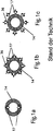
- Figures 1a, 1b and 1c each show schematic cross-sectional views of exemplary embodiments of the prior art according to the DE 10 2010 005 893 A1 (there the Figures 6b, 6c and 6d ).
- FIG. 1a a UV irradiation units is shown, which shows a UV irradiation device 17 integrated into the wall of a line system 14.
- the UV irradiation devices 17 protrude with their tip areas in each case into the line interior.
- the light sources are therefore in direct contact with the medium flowing in the interior and must be resistant and sealed against this. A simple exchange is no longer possible without further ado. For this, the system must be switched off.
- FIG. 1b a plurality of UV irradiation means 17 are shown in the form of UV LEDs 36, which are integrated into the wall of the conduit system 14.
- the UV LEDs 36 are therefore located in recesses of the pipe wall.
- the prior art recesses shown show that there is regularly a greater wall thickness of the tubing to accommodate the UV light sources. This results in an extension of the path that the UV light has to travel through the tube to the medium, resulting in losses.
- a larger part of the light emitted laterally by the UV light source will leave the tube to the outside or be guided in the tube wall and therefore can not be used for sterilization. This geometry is therefore poorly suited for non-directional light sources.
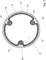
- FIG. 2 shows a schematic cross-sectional view of an exemplary embodiment of a tube 10 according to the invention with 3 UV light sources 20a, 20b and 20c and a reflector 30.
- the in FIG. 2 embodiment shown has a tubular interior 40 through which flows perpendicular to the plane of a liquid and / or gas.
- the tube 10 is constructed of a UV-transparent glass. The glass can be selected as desired, provided that it is suitable for the purpose.
- the pipe wall has 3 indentations 25a, 25b and 25c.
- both the tube outer wall 60 and the tube inner wall 70 are concurrently turned inside out at the same point, so that the indentations 25a, 25b and 25c extend into the inner space 40.
- the indentations 25a, 25b and 25c each form cavities or depressions, in each of which UV light sources 20a, 20b and 20c are arranged, which are preferably arranged parallel to the flow direction of the medium to be sterilized.
- the UV light sources 20a, 20b and 20c are in the present case completely absorbed by the recesses 25a, 25b and 25c shown and are located almost completely within the tube inner wall 70, in the case shown the tube inner radius, when the tube 10 would run so that no indentations exist.
- the number of UV light sources 20a, 20b and 20c coincides with the number of indentations 25a, 25b and 25c, so that in each indentation 25a, 25b and 25c there is a respective UV light source 20a, 20b and 20c ,
- additional recesses could be present or in a recess could be more than one UV light source, for example, a bundle of UV light sources present.
- Fig. 2 the recesses 25a, 25b and 25c shown adapted to the shape of the UV light sources 20a, 20b and 20c, so that they are completely absorbed in the cavity formed and no longer protrude to the outside.
- UV light sources 20a, 20b and 20c are arranged symmetrically in the round glass tube 10, ie they span an equilateral triangle, with the UV light sources 20a, 20b and 20c respectively at the corners of the triangle.
- the UV light must take a shorter path through the pipe wall due to the inwardly extending indentations 25a, 25b and 25c, to reach the interior 40, where the medium to be sterilized is located.
- a large portion of the UV light can pass directly through the tube wall into the interior space 40, where the medium to be sterilized is located.
- This geometry is advantageous in order to obtain the most homogeneous possible radiation distribution with high radiation density, whereby a radiation intensity minimum usually occurring between the individual UV light sources can be largely avoided.
- one or more recesses may be provided in the glass tube 10. These preferably contain no UV light source, but for example a sensor.
- a reflector 30 is provided to reflect the outwardly emitted UV light back into the tube 10 into it.
- the type, shape size and structure of the reflector 30 are according to the invention not further limited.
- a reflector 30 may be any type of coated surface for reflecting light, such as a reflective sheet, a mirror, and the like.
- the reflector 30 is arranged lying around the entire arrangement.
- the reflector 30 has a round shape and abuts against the tube outer wall 60.
- the reflector 30 can be applied directly to the pipe outer wall 60. Due to the construction shown, a particularly simple reflector geometry is possible, the reflector 30 is directly on the pipe 10 and is held and stabilized by this. The reflector can also be attached directly to the tube 10 or applied to this.
- the device can be completely enclosed by a tube which simultaneously serves as a reflector and rests directly against the tube 10.
- the reflector 30 can also be a UV-reflecting coating which is applied directly to the tube 10, for example vapor-deposited.
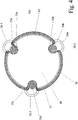
- FIG. 3 shows a schematic cross-sectional view of another exemplary embodiment of a tube 10 according to the invention with 3 UV light sources 20a, 20b and 20c and reflectors 30a and 30b.
- the embodiment of the invention is similar to that in FIG Fig. 2
- each UV light source 20a, 20b and 20c is assigned a respective reflector 30a (30.1, 30.2 and 30.3).
- the individual reflectors 30a (30.1, 30.2 and 30.3) assigned to the respective UV light sources 20a, 20b and 20c are freely selectable in terms of shape, size and shape.
- the reflectors 30.1, 30.2 and 30.3 are shown in the form of spherical cutouts.
- the three reflectors shown 30.1, 30.2 and 30.3 are all the same size and shown with the same shape. However, this is not always necessary.
- Other reflector sizes and designs are possible, which may be different in each UV light source 20a, 20b, and 20c.
- another reflector 30b is arranged around the tube 10 itself.
- a reflector 30b is disposed directly around the tube 10 and is held and stabilized by it.
- the reflector can also be attached directly to the tube 10 or applied in the form of a UV-reflective coating on this.
- the UV light must have a shorter path to the interior space 40 due to the UV light sources 20a, 20b and 20c present in the indentations 25a, 25b and 25c, which are arranged to be inside the pipe inner wall 60 (without indentations) take where the medium to be sterilized is located.
- the proportion of UV light that is initially reflected by a reflector before it enters the interior is significantly reduced, a low-loss coupling of the UV light results, whereby a better utilization of the UV radiation is achieved.
- FIG. 4 that are similar to FIG. 3 is a schematic cross-sectional view of another exemplary embodiment of the invention a round UV-transparent glass tube with 3 UV light sources is shown, wherein the tube has a reflector inside and in addition each UV light source is associated with a reflector.
- the inner reflector is in the region of the indentations 25 a, 25 b and 25c of course omitted.
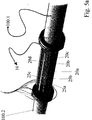
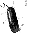
- FIG. 5a Figure 3 is a three-dimensional schematic view of an exemplary apparatus according to an embodiment of the invention.
- the pipe 10 is installed in a pipe system, for example installed between the metal pipes 100.1 and 100.2.
- the tube 10 is constructed of UV-transparent glass and has indentations 25a, 25b, 25c .... in which the UV light sources 20a, 20b, 20c ... are located.
- FIG. 5b is a three-dimensional schematic view of the tube 10 of FIG Fig. 5a shown with a plurality of UV light sources 20a, 20b, 20c ..., which are connected via the terminals 22 to a power source.
- the UV-transparent glass used is not particularly limited.
- For particularly preferably used UV-transparent glasses is in FIG. 6 the transmission curve is shown in a graphical representation. In this case, the transmission (in%) was plotted against the wavelength (in nm) for some preferred UV-transparent glasses.
- Fig. 6 shows the UV transmission for glass 1, glass 2 and glass 3.
- FIGS. 1 to 6 illustrate only exemplary embodiments possible. These are not intended to be limiting, but merely represent examples of possible embodiments. Other possibilities for execution are conceivable.
Abstract
Description
- Die Erfindung betrifft eine Vorrichtung zur Entkeimung von Gasen und/oder Flüssigkeiten.
- Es ist bereits bekannt UV-Strahlung zur Behandlung, insbesondere Entkeimung oder Sterilisierung bzw. Desinfizierung, von Wasser, Luft oder Oberflächen einzusetzen. Relativ verbreitet ist bislang die Trinkwasseraufbereitung mit UV-Strahlung, wobei die Keimzahl im Wasser zuverlässig und in Abhängigkeit zur Dosis stark reduziert werden kann. Durch die UV-Strahlung werden Mikroorganismen, wie Krankheitserreger, insbesondere Bakterien oder Viren, inaktiviert.
- Die UV-Entkeimung weist eine Reihe an Vorteilen gegenüber der herkömmlichen Desinfektion, basierend auf chemischen Verfahren, auf:
- Bei der UV-Entkeimung handelt es sich um ein einfaches und schnell wirksames Verfahren, wobei die Entkeimung unmittelbar während der Belichtung des Mediums erfolgt. Ein großer Vorteil der UV-Entkeimung ist weiterhin, dass weder Geschmack, Geruch noch der pH-Wert des entkeimten Mediums beeinflusst wird, was einen wesentlichen Unterschied zur chemischen Behandlung von Trink- oder Prozesswasser darstellt. Im Gegensatz zum chemischen Desinfektionsverfahren sind zusätzliche Zugaben von desinfizierenden Mitteln nicht erforderlich, Wartung- und Überwachung von Dosieranlagen entfallen und spezielle Sicherheitsbestimmungen sind ebenfalls nicht notwendig. Ein weiterer Vorteil ist die Umweltfreundlichkeit, da keine Nebenreaktionen unter Bildung unerwünschter Verbindungen auftreten. Anders als übliche Desinfektionsmittel werden bei einer UV-Entkeimung keine mutationsbedingten Resistenzen entwickelt, wie dies beispielsweise bei krankenhausspezifischen Keimen (z.B. Antibiotika-Resistenz) häufig der Fall ist.
- Die UV-Entkeimung ist auch im großen Maßstab möglich, beispielsweise in der kommunalen Trinkwasseraufbereitung. Auch ein Dauerbetrieb ist möglich, um die Keimzahl ständig gering zu halten.
- Bei der UV-Entkeimung werden üblicherweise Quecksilberdampflampen eingesetzt, welche Strahlung bei einer Wellenlänge um 254 nm emittieren. Kürzere Wellenlängen unterhalb 200 nm sind so kurzwellig, dass sie durch molekularen Sauerstoff absorbiert werden, wodurch der molekulare Sauerstoff in freie Sauerstoffradikale gespalten wird, und mit weiteren Sauerstoffmolekülen zu Ozon weiterreagieren kann. Derartige kurzwellige UV-Strahlung wird u.a. zur Herstellung von hochreinem Wasser eingesetzt.
- Aus dem Stand der Technik sind zahlreiche Vorschläge für die UV-Entkeimung bekannt geworden. Einige hiervon sollen nachfolgend erläutert werden:
- So beschreibt die
DE 38 37 905 A1 ein Verfahren und eine Vorrichtung zur Behandlung, insbesondere Entkeimung, von Flüssigkeiten und/oder Gasen mittels UV-Lichtquellen, wobei die Vorrichtung eine rohrförmige Reaktionskammer für das zu behandelnde Medium und mindestens zwei UV-Lichtquellen umfasst, wobei voneinander verschiedene UV-Lichtquellen vorgesehen sind, die jeweils unterschiedliche Wellenlängen abstrahlen und gemeinsam, in wählbaren Kombinationen miteinander oder getrennt im Wechsel betreibbar sind. Die UV-Lichtquellen befinden sich entweder in der Reaktionskammer und werden in das Medium eingetaucht und von diesem umspült oder werden außerhalb und auch mit Abstand von der Reaktionskammer angebracht. - Die
DE 38 24 647 A1 bezieht sich auf eine Vorrichtung zur Bestrahlung von Medien mittels UV-Licht, bestehend aus einem vom Medium durchströmten Rohrkörper aus UV-durchlässigem Werkstoff und mindestens zwei außen achsparallel angeordneten UV-Lichtquellen mit Reflektoren, wobei die Lichtquellen UV-Flachstrahler darstellen, die einen länglich, flachovalen Querschnitt mit Breit- und Schmalseite aufweisen, wobei die Hauptachsen der UV-Lichtquellen jeweils auf den Mittelpunkt des Rohrkörperquerschnitts gerichtet sind. Die UV-Lichtquellen sind kranzförmig und achsparallel um den mediumdurchströmten Rohrkörper angeordnet. Gemäß einer Ausführungsform liegen die Flachstrahler mit der dem Rohrkörper zugewandten Schmalseite am Rohrkörper an. - Die
US 5 133 932 offenbart eine Vorrichtung zur Sterilisierung von Blut und anderen Flüssigkeiten biologischen Ursprungs, indem ein für UV-Strahlung transparenter Behälter mit der zu sterilisierenden Flüssigkeit gedreht und gleichzeitig von außen mit UV-Strahlung bestrahlt wird. Der Behälter kann eine wellenförmige Oberfläche aufweisen. Die UV-Lichtquellen sind jedoch außerhalb des drehbaren Behälters angeordnet. - Weiterhin beschäftigt sich die
DE 196 17 467 A1 mit einer Vorrichtung zum Entkeimen von Wasser mittels UV-C-Strahlen, wobei das Wasser durch ein Quarzglasrohr fließt und die ein oder mehreren UV-Strahler um das Quarzglasrohr herum angeordnet sind. - Die
DE 10 2010 005 893 A1 offenbart eine Anlage zur Herstellung von Reinstwasser, umfassend wenigstens einen Einlass für das zu reinigende Wasser, eine Reinigungseinheit, eine UV-Bestrahlungseinrichtung mit wenigstens einer UV-Strahlen emittierenden Lichtquelle, die zur Bestrahlung des durch die UV-Bestrahlungseinrichtung strömenden Wassers ausgebildet ist, sowie einen Auslass. Die UV-Bestrahlungseinrichtungen, beispielsweise in Form von UV-LEDs, sind dabei entweder außerhalb des Leitungssystems 14 angeordnet (Fig. 6d ) oder in die Wandung des Leitungssystems 14 integriert (Fig. 6a, 6b und 6c ). Besonders bevorzugt ragt die UV-Bestrahlungseinrichtung zumindest teilweise in das strömende Wasser hinein. - Die
WO 2009/013507 A1 betrifft eine Behandlungsvorrichtung zum mindestens teilweise Entkeimen eines Fluids, wie Wasser, umfassend eine Leitung zur Beförderung eines zu behandelnden Fluidstroms, eine Vielzahl von LEDs zur Emission von UV-Licht in das Fluid sowie einen Kontrollkreislauf zur Steuerung der LEDs mittels eine gepulsten Signals damit die Lichtquelle pulsiert. Die UV-LEDs sind hierbei derart angeordnet, dass der Fluidstrom unmittelbar über eine Oberfläche jeder Lichtquelle fließt. Der direkte Kontakt des Fluids mit der/den UV-Lichtquellen soll aufgrund der größeren Nähe von Lichtquelle zu behandelnder Flüssigkeit eine größere Behandlungseffizienz bewirken. Weiterhin soll ein Kühleffekt der UV-LEDs durch die Flüssigkeit vorliegen, so dass die LED mit höchster UV-Lichtintensität betreibbar sein soll, wodurch wiederum die Einsatzmöglichkeiten vergrößert und die Effizienz verbessert werden sollen. - Problematisch beim direkten Kontakt von UV-Lichtquelle und zu behandelndem Medium ist jedoch, dass die Oberfläche der UV-Lichtquelle gegenüber dem Medium beständig und gegen dieses abgedichtet sein muss. Jede UV-LED muss dabei für sich abgedichtet werden. Der Kühleffekt, beispielsweise einer Flüssigkeit, kann dann nicht mehr genutzt werden, wenn die Flüssigkeit selbst nicht kühl, sondern warm oder gar heiß ist. Dann bewirkt die heiße Flüssigkeit sogar eine zusätzlich Aufheizung der UV-LEDs und kann deren Haltbarkait deutlich beschränken.
- Auch haben die hier geschilderten Behandlungssysteme den Nachteil, dass kein einfacher Austausch der UV-Lichtquelle erfolgen kann, da diese in direktem Kontakt mit dem zu behandelnden Medium steht. Eine Abschaltung des gesamten Systems wird daher nötig, worunter die Effizienz des Verfahrens leidet.
- Die
US 7 270 748 B1 beschreibt ein Wasserreinigungssystem für einen Wasserhahn unter Verwendung von UV-Strahlung. Ein Teil des Wasserdurchlaufs weist eine Vielzahl von UV-LEDs auf, die um die transparente Leitung herum angeordnet und in diese eingebettet vorliegen können. - Die
US 2003/0170151 A1 offenbart ein System, in dem ein Fluid UV-Strahlung ausgesetzt wird, wobei das System eine Leitung zur Beförderung des Fluids umfasst, wobei die Leitung Ablenkeinrichtungen aufweist, um den Strom des Fluids gleichmäßiger zu gestalten. Die UV-Lichtquellen sind dabei in der Leitung angeordnet oder können auch auf der Ablenkeinrichtung vorgesehen werden. Dabei sind die UV-Lichtquellen wieder in direktem Kontakt mit dem zu behandelnden Fluid, woraus die bereits geschilderten Nachteile resultieren. - Die
US 2010/0253207 A1 beschreibt eine flache Entladungslampe für Erzeugung von UV-Strahlung einer sehr speziellen Ausgestaltung, die u.a. auch zur Entkeimung/Sterilisierung von Luft, Wasser oder Oberflächen eingesetzt werden kann. - Aus dem Stand der Technik sind demnach im Wesentlichen zwei unterschiedliche Aufbaukonzepte für UV-Entkeimungsanlagen bekannt:
- (a) Anlagen, bei denen die UV-Lichtquellen vom zu entkeimenden Medium umspült werden, und
- (b) Anlagen, bei denen die Lichtquellen außerhalb des zu entkeimenden Mediums angeordnet sind.
- Die vorliegende Erfindung beschäftigt sich mit Anlagen vom Typ (b) und stellt eine Verbesserung derartiger Anlagen des Typs (b) dar.
- Nachteile der bekannten Anlagen vom Typ (b) sind geringe Effizienz und großer Bauraum. Die UV-Lichtquellen befinden sich bei diesen Anlagen außerhalb eines UV-durchlässigen Rohres, in dem das zu entkeimende Medium fließt. Um eine zur Entkeimung erforderliche Mindestbestrahlung im vollständig durchflossenen Innenraum zu garantieren, muss entweder eine Vielzahl von UV-Lichtquellen um das Rohr herum angeordnet werden oder über ein aufwändiges, vergleichsweise viel Platz benötigendes Reflektorsystem die UV-Strahlung weniger Lichtquellen in ausreichendem Maße verteilt werden. Um eine ausreichende Entkeimungsleistung zu erreichen, müssen jedoch insbesondere zwei Kriterien erfüllt werden: Die Strahlungsintensität muss über den gesamten zu entkeimenden Bereich ausreichend hoch sein, d.h. die Intensität der Strahlung zur Entkeimung sollte ein bestimmtes Strahlungsminimum nicht unterschreiten. Weiterhin sollte eine möglichst homogene Verteilung der Strahlung im zu entkeimenden Medium vorliegen. Aus dem Stand der Technik bekannte Anlagen haben jedoch typischerweise das Problem einer schlechten UV-Lichtausnutzung, verursacht durch Abschattungen, Mehrfachreflexionen und Verlustmechanismen, insbesondere an den Spiegeloberflächen des Reflektorsystems. Durch die in der Regel ungerichtete Abstrahlung der UV-Lichtquellen geht nur ein geringer Anteil der Strahlung auf direktem Weg durch das UV-durchlässige Rohr in das zu entkeimende Medium. Der übrige Anteil muss über Reflektoren in das Rohr gelenkt werden. Reflektormaterialien, wie etwa Aluminium, absorbieren jedoch einen signifikanten Teil der UV-Strahlung, beispielsweise bei Aluminium sind dies ca. 15% bei einer Wellenlänge von 254 nm. Dieser Anteil der UV-Strahlung geht verloren und steht für die Entkeimung nicht mehr zur Verfügung.
- Weiterhin benötigen die bekannten Anordnungen von UV-Lichtquellen und Reflektoren viel Platz und eignen sich daher nur bedingt für Anwendungen mit geringem Bauraum.
- Demnach liegt der vorliegenden Erfindung die Aufgabe zugrunde, eine Vorrichtung bereitzustellen, welche die Nachteile des Standes der Technik vermeidet und eine effektive Entkeimung von Flüssigkeiten oder Gasen mittels UV-Strahlung unter Beibehaltung der bekannten Vorteile einer UV-Entkeimung bereitstellt, wobei eine bessere Ausnutzung der durch die Lichtquellen erzeugten UV-Strahlung erzielt wird. Weiterhin soll die erfindungsgemäße Vorrichtung eine höhere Kompaktheit hinsichtlich der Bauweise ermöglichen.
- Erfindungsgemäß wird die Aufgabe der vorliegenden Erfindung durch eine Vorrichtung zur Entkeimung von Gasen und/oder Flüssigkeiten gelöst, umfassend ein Rohr aus UV-transparentem Glas, das einen hohlen Innenraum und eine Rohrwand mit einer Rohrinnenwand und einer Rohraußenwand aufweist, sowie mindestens eine UV-Lichtquelle,
wobei das UV-transparente Glasrohr an mindestens einer Stelle eine Einbuchtung in den Innenraum
aufweist und
in der mindestens einen Einbuchtung mindestens eine UV-Lichtquelle angeordnet ist. - Die Geometrie der Erfindung basiert daher auf einer Anordnung mindestens einer UV-Lichtquelle, die zumindest teilweise von der Glaswand des Rohrs umgeben und in dieser angeordnet ist. Die Form der Glaswand des Rohrs ist dabei derart ausgestaltet, dass die Glaswand die UV-Lichtquelle zumindest teilweise, bevorzugt vollständig aufnehmen und unterzubringen kann. Zum Vorsehen der einen oder mehreren UV-Lichtquellen werden daher Einbuchtungen der Glasrohrwand bereitgestellt. Es liegt somit eine klare räumliche Trennung von UV-Lichtquelle und zu behandelndem Medium vor, das zu entkeimende Gas und/oder die zu entkeimende Flüssigkeit befindet sich nicht in direktem Kontakt mit der UV-Lichtquelle.
- Eine "Einbuchtung" soll im Rahmen der vorliegenden Erfindung eine Einstülpung der Glaswand des Glasrohres vorbestimmter Größe darstellen, in der zumindest eine UV-Lichtquelle angeordnet ist. Dabei sind die Rohrinnenwand und die Rohraußenwand gleichzeitig an derselben Stelle nach Innen gestülpt und bilden zusammen einen zur Rohraußenseite offenen Hohlraum aus, in den die mindestens eine UV-Lichtquelle aufgenommen wird. Der von der Einbuchtung gebildete Hohlraum ist zur Rohraußenseite offen, um den Zugang zur UV-Lichtquelle zu erleichtern. Hierdurch kann die UV-Lichtquelle in einfacher Weise an die elektrischen Anschlüsse angebracht und wieder von diesen abgekoppelt werden, so dass die UV-Lichtquellen ohne weiteres ausgetauscht werden können. Die erfindungsgemäßen Einbuchtungen erstrecken sich daher zumindest teilweise in den Innenraum des Glasrohrs.
- Erfindungsgemäß können auch Aussparungen im Glasrohr vorhanden sein. Eine "Aussparung" bedeutet erfindungsgemäß eine Vertiefung vorbestimmter Größe, die entweder in der Rohraußenwand oder der Rohrinnenwand des Glasrohrs vorgesehen ist. Bei Vorsehen einer Aussparung wird Material abgetragen: Wenn beispielsweise in der Rohrinnenwand eine oder mehrere Aussparungen vorgesehen sind, wird hierfür Material entfernt, um die Aussparungen auszubilden, jedoch bleibt die Rohraußenwand hiervon unberührt. Wenn beispielsweise in der Rohraußenwand eine oder mehrere Aussparungen vorgesehen sind, wird hierfür Material entfernt, um die Aussparungen auszubilden, jedoch bleibt die Rohrinnenwand hiervon unberührt. Die Aussparungen erstrecken sich im Gegensatz zu den erfindungsgemäß vorgesehenen Einbuchtungen nicht in den Innenraum des Glasrohrs, dieser bleibt bei Vorsehen von Aussparungen unberührt.
- Die gegebenenfalls zusätzlich zu den erfindungsgemäßen Einbuchtungen vorliegenden Aussparungen können eine oder mehrere UV-Lichtquellen aufnehmen. Bevorzugt dienen die optionalen Aussparungen jedoch für andere Funktionen und enthalten keine UV-Lichtquellen. Beispielsweise können die Aussparungen einen Sensor enthalten oder andere technische Einrichtungen, welche für die Vorrichtung der Erfindung eingesetzt werden können. Nach einer weiteren bevorzugten Ausführungsform können auch nur Einbuchtungen im Glasrohr vorgesehen sein, Aussparungen liegen dann nicht vor.
- Die Anzahl der verwendeten UV-Lichtquellen kann erfindungsgemäß relativ beliebig ausgewählt werden. Es ist zumindest eine UV-Lichtquelle vorhanden. Es können auch mindestens 2 UV-Lichtquellen vorliegen. Beispielhafte Ausführungsformen umfassen 1 bis 8 UV-Lichtquellen, bevorzugter 1 bis 6 UV-Lichtquellen, insbesondere 1 bis 5 UV-Lichtquellen, ganz besonders bevorzugt sind 1 bis 4 oder 1 bis 3 UV-Lichtquellen im Glasrohr. Wenn relativ stark strahlende UV-Lichtquellen, wie übliche UV-Stablampen, zum Einsatz kommen, ist es aus Kostengründen bevorzugt, eine möglichst geringe Anzahl an UV-Lichtquellen einzusetzen, bevorzugt 1 bis maximal 3 UV-Lampen. Wenn relativ schwach strahlende UV-Lampen zum Einsatz kommen, wie UV-LEDs, so kann erfindungsgemäß auch eine deutlich größere Anzahl an UV-Lichtquellen eingesetzt werden, beispielsweise 100 UV-LEDs oder mehr. In jedem Fall sollte eine vordefinierte Mindeststrahlungsintensität nicht unterschritten werden und eine möglichst gleichmäßige Verteilung des UV-Lichts vorliegen, um eine ausreichende Entkeimung zu gewährleisten.
- Die Anordnung der UV-Lichtquellen erfolgt, je nach der gewählten Anzahl, derart, dass vorzugsweise eine möglichst gleichmäßige Verteilung der Lichtquellen über den gesamten Rohrumfang vorliegt. Besonders bevorzugt sind daher symmetrische Anordnungen, wie z.B. achsen- bzw. spiegelsymmetrische, rotationssymmetrische oder punktsymmetrische Anordnungen. Bei einer nicht symmetrischen Anordnung der UV-Lichtquellen, können Stellen im zu entkeimenden Medium resultieren, an die deutlich weniger UV-Licht gelangt, was vermieden werden sollte. Bei Vorsehen von 3 UV-Lichtquellen werden die UV-Lichtquellen daher vorzugsweise derart angeordnet, dass diese ein gleichseitiges Dreieck aufspannen (gedachte Verbindungslinien zwischen den einzelnen UV-Lichtquellen als Ecken stellen ein gleichseitiges Dreieck dar). Bei 4 UV-Lichtquellen werden diese vorzugsweise an den Ecken eines gedachten Quadrats angeordnet. Bei 5 UV-Lichtquellen befinden sich diese vorzugsweise in den Ecken eines Fünfecks mit gleichlangen Seiten etc.
- Die Auswahl einer geeigneten Anordnung der UV-Lichtquellen hängt neben der Anzahl, Größe und Form der UV-Lichtquellen auch von der gewählten Form, Größe und dem Querschnitt des Glasrohrs ab. Ein Fachmann aus dem Stand der Technik kann ohne weiteres eine geeignete, vorzugsweise möglichst symmetrische Anordnung der UV-Lichtquellen für jeden Rohrtyp auswählen.
- Die Anzahl der Einbuchtungen stimmt vorzugsweise mit der Anzahl der verwendeten UV-Lichtquellen überein. In Einzelfällen können aber auch mehr Einbuchtungen vorliegen als UV-Lichtquellen oder es können mehrere UV-Lichtquellen in einer Einbuchtung vorliegen.
- Weiterhin bevorzugt ist jeweils nur eine UV-Lichtquelle in einer Einbuchtung vorgesehen. Dies führt zu einer besseren Ausnutzung der UV-Strahlung unter Vermeidung einer gegenseitigen Abschattung der UV-Lichtquellen. Bei Verwendung von UV-LEDs sind im Gegensatz hierzu mehrere, möglicherweise sogar eine große Anzahl an UV-Lichtquellen in einer Einbuchtung angeordnet. Dies liegt daran, dass LEDs gerichtet abstrahlen und so eine gegenseitige Abschattung vermieden werden kann.
- Die erfindungsgemäße Anordnung hat besonders bei nicht vollständig UV-transparenten Rohrmaterialien, insbesondere bei den eingesetzten UV-transparenten Gläsern Vorteile. Da Glasrohre von UV-transparenten Gläsern bei einer Wellenlänge von 254 nm eine Absorption von >10% auf 1 mm Materialdicke zeigen können, ist es bei der erfindungsgemäßen Vorrichtung besonders vorteilhaft, dass das Licht nur kurze Wege durch das Glas zurücklegt, und nicht bereits im Rohrmaterial zu hohen Anteilen absorbiert wird.
- Der Begriff "UV-transparent" bedeutet, dass das erfindungsgemäß eingesetzte Glas des Rohrs eine hohe UV-Transmission aufweist, was bedeutet, dass eine UV-Transmission von mindestens 75 % bei einer Wellenlänge von 254 nm und einer Schichtdicke des Glases von 1 mm vorliegt. Nach einer besonders bevorzugten Ausführungsform zeigt das Glas des Rohrs eine Transmission bei einer Schichtdicke von 1 mm im UV-Bereich, die bei 200 nm < 0,5% liegt und bei 254 nm > 75% liegt. Noch bevorzugter wird eine Transmission bei einer Schichtdicke von 1 mm im UV-Bereich bei 200 nm < 0,3% und bei 254 nm > 80 % erhalten.
- Die erfindungsgemäße Lösung der Bereitstellung der UV-Lichtquellen in Einbuchtungen zeichnet sich dadurch aus, dass die UV-Lichtquellen in Richtung zum Innenraum des Rohrs versetzt sind. Es resultiert ein hoher Anteil an UV-Strahlung, der direkt durch das Glasrohr in das Medium geführt wird, ohne vorher unter Verlusten reflektiert zu werden. Durch die erfindungsgemäß bereitgestellte Geometrie wird weiterhin eine homogenere Lichtverteilung im Rohrinnenraum erzielt, wodurch die Entkeimungsleistung erhöht wird. Durch die erfindungsgemäße Anordnung wird zudem eine hohe Kompaktheit des Systems zur Verfügung gestellt.
- So gelangt bei der erfindungsgemäßen Vorrichtung mehr UV-Strahlung an/in das Medium, als bei einer herkömmlichen Anordnung, wo sich die UV-Lichtquellen außerhalb des das zu entkeimende Medium führenden Rohrs befinden. Im Gegensatz zu den oben beschriebenen Anlagen gemäß Typ (a), die in der Regel auf einem sehr komplexen Systemaufbau beruhen, ist die erfindungsgemäße Vorrichtung relativ einfach aufgebaut. Insbesondere muss in Systemen vom Typ (a) die UV-Lichtquelle von außen zugänglich sein, was zusätzlichen konstruktiven Aufwand bedeutet, womit wiederum hohe Kosten verbunden sind. Die erfindungsgemäße Vorrichtung ermöglicht demgegenüber einen einfachen Zugang zur UV-Lichtquelle, so dass diese ohne weiteres ausgetauscht werden kann. Aufgrund des erfindungsgemäß einfachen Systemaufbaus kann ein nahezu ungestörter Durchfluss des Mediums durch das Glasrohr erfolgen.
- Gemäß einer vorteilhaften Ausführungsform der Erfindung kann die Form der Einbuchtungen an die Form der verwendeten UV-Lichtquellen angepasst sein. Die Einbuchtung ist zweckmäßigerweise so ausgestaltet, dass diese die UV-Lichtquelle zumindest teilweise, bevorzugt vollständig, in sich aufnehmen kann. Die auf die Lichtquelle angepasste spezielle Form der Einbuchtung dient zur Optimierung der Lichtverteilung, so dass alle Bereiche innerhalb des Rohres möglichst eine ausreichende Bestrahlungsstärke erhalten. Dies spielt insbesondere am inneren Rohrrand, mittig zwischen einzelnen Lichtquellen eine Rolle, wo ansonsten nur geringe Strahlungsintensität vorliegen würde.
- Nach einer bevorzugten Ausführungsform der Erfindung wird die mindestens eine UV-Lichtquelle in der mindestens einen Einbuchtung derart angeordnet, dass sich die mindestens eine UV-Lichtquelle zumindest teilweise, besonders bevorzugt vollständig, innerhalb der Rohrinnenwand des UV-transparenten Glasrohrs befindet, wenn die Rohrinnenwand ohne Einbuchtungen vorliegen würde. Unter "Rohrinnenwand" wird hier die Innenseite des Rohrs verstanden, wie diese ohne Einbuchtungen aussehen würde, d.h. wenn keine Einbuchtungen im Glasrohr vorhanden wären.
- Nach der weiteren bevorzugten Ausführungsform, für den Falle, dass das Glasrohr einen runden Querschnitt aufweist, reichen die Einbuchtungen vorzugsweise so weit in den Innenraum des Glasrohrs, dass sich die darin befindlichen UV-Lichtquellen zumindest teilweise, besonders bevorzugt vollständig, innerhalb des Innenradius des Rohrs befinden. Unter "Rohrinnenradius" wird hier die Innenseite des Rohrs verstanden, wie diese ohne Einbuchtungen aussehen würde, d.h. wenn keine Einbuchtungen im Glasrohr vorhanden wären.
- Durch diese erfindungsgemäße Geometrie kann ein Großteil der Strahlung (mindestens 180°-Abstrahlwinkel) auf direktem Weg durch die Glaswand in den Innenbereich gelangen und geht nicht durch Rückreflektionen in die Lichtquellen und/oder anderweitige Absorption beispielsweise am Reflektor verloren. Besonders bevorzugt sind Anordnungen, bei denen die UV-Lichtquellen derart angeordnet werden, dass sich diese innerhalb der Rohrinnenwand befinden, wie oben definiert, so dass eine besonders günstige Strahlungsverteilung resultiert, bei der der überwiegende Teil des UV-Lichts auf direktem Weg durch das Glas in den Innenraum gelenkt wird. Im Vergleich zu herkömmlichen Anordnungen gelingt es erfindungsgemäß daher, dass nur noch ein geringer Strahlungsanteil über Reflektoren zurückreflektiert wird. Es resultiert somit eine höhere Gesamteffizienz des Systems.
- Die Einbuchtungen sind erfindungsgemäß bevorzugt lokal begrenzt im Glasrohr vorgesehen, d.h. die Einbuchtungen weisen eine vordefinierte Form und Größe auf; diese liegen vorzugsweise nur im Bereich einer UV-Lichtquelle oder einer Gruppe von UV-Lichtquellen vor und dehnen sich nicht weiter längs der Rohrachse aus. Es kann aber auch vorteilhaft sein, beispielsweise aus produktionstechnischen Gründen, eine Einbuchtung vorzusehen, die größer ist als die enthaltene UV-Lichtquelle. Die Einbuchtungen können beispielsweise auch umlaufend um das Rohr vorliegen.
- Bevorzugt ist jeweils nur eine UV-Lichtquelle oder eine Gruppe von UV-Lichtquellen in einer Einbuchtung vorgesehen. Wenn erfindungsgemäß nur Einbuchtungen im Glasrohr vorgesehen sind, kann dies für das eingesetzte Herstellungsverfahren besonders zweckmäßig sein; dies wird noch im Einzelnen beschrieben.
- Eine weitere bevorzugte Komponente in der erfindungsgemäßen Vorrichtung ist ein Reflektor, der außerhalb des Rohres angeordnet wird, um das nach außen abgestrahlte UV-Licht wieder in das Rohr hinein zu reflektieren. Die Reflektoren dienen zudem dazu, durch eine gezielte Reflektorgeometrie den Anteil der in die Lichtquelle zurückreflektierten UV-Strahlung auf ein Minimum zu reduzieren, bzw. aus dem Medium, insbesondere auf der gegenüberliegenden Seite, austretendes UV-Licht in das Medium zurück zu reflektieren.
- Die Art, Form, Größe und der Aufbau des Reflektors sind erfindungsgemäß nicht weiter beschränkt. Ein Reflektor kann jede Art von Bauteil sein, umfassend eine Oberfläche zur Reflektion von Licht. Der Reflektor kann in verschiedenen Varianten ausgeführt werden. Der Reflektor kann beispielsweise aus flexiblem oder starrem bzw. festem Material aufgebaut sein. Bevorzugt weist der Reflektor eine Form und Größe auf, die an die Form und Größe der erfindungsgemäßen Vorrichtung, insbesondere das UV-transparente Glasrohr mit mindestens einer UV-Lichtquelle, angepasst ist.
- Vorteilhafterweise kann der Reflektor beispielsweise um das Glasrohr herum angeordnet sein und dieses vollständig einhüllen, d.h. der Reflektor ist um die gesamte erfindungsgemäße Vorrichtung herum angeordnet. Der Reflektor kann hierfür vorzugsweise die Form eines Rohrs aufweisen, beispielsweise ein Rohr aus Aluminium, Edelstahl oder einem anderen Material, kann gegebenenfalls mit einer entsprechenden reflektierenden Beschichtung versehen sein und einen größeren Durchmesser als das Glasrohr aufweisen, das der Reflektor vollumfänglich umschließt. Dabei kann die Form und insbesondere der Querschnitt des Reflektorrohrs der Form bzw. dem Querschnitt des Glasrohres ähnlich sein. Das Reflektorrohr kann gleichzeitig als Schutz für das Glasrohr dienen.
- Nach einer weiteren besonders bevorzugten Ausführungsform der Erfindung ist ein Reflektor unmittelbar auf dem Glasrohr angebracht, wobei gegebenenfalls im Bereich der Einbuchtungen kein Reflektor vorgesehen ist. Beispielsweise kann der Reflektor auf der Rohraußenwand aufgebracht sein, ausgenommen in dem Bereich, wo die Einbuchtungen und gegebenenfalls Aussparungen vorliegen, bevorzugt in Form einer UV-reflektierenden Beschichtung auf der Rohraußenwand.
- Nach einer weiteren bevorzugten Ausführungsform der Erfindung kann der Reflektor auch auf der Innenseite des Glasrohrs angebracht sein, beispielsweise kann eine UV-reflektierende Beschichtung auf der Rohrinnenwand vorgesehen werden. Dabei sind die Einbuchtungen für die UV-Lichtquellen wieder ausgespart. Das reflektierte Licht wird hierbei nicht durch die Restabsorption des Glases abgeschwächt.
- Der Reflektor kann sich auch aus mehreren verschiedenen Komponenten zusammensetzen, z.B. einzelnen Reflektoren, die vorzugsweise hinter den UV-Lichtquellen angeordnet sind. Bevorzugt ist dann jeder UV-Lichtquelle oder einer Gruppe von UV-Lichtquellen ein Reflektor zugeordnet, um eine möglichst hohe Strahlungsenergie für die Bestrahlung des im Rohr fließenden oder strömenden Mediums zur Verfügung zu stellen. Die einzelnen den jeweiligen UV-Lichtquellen zugeordneten Reflektoren sind in Form und Gestalt vorzugsweise den Formen eines Kegelschnitts angenähert, beispielsweise parabolisch oder elliptisch.
- Es kann auch eine Kombination von unterschiedlichen Reflektoren vorliegen. Bevorzugt ist auf der Außen- oder der Innenseite des Glasrohrs ein Reflektor vorgesehen und zusätzlich an jeder UV-Lichtquelle ebenfalls ein Reflektor vorgesehen. Beispielsweise kann ein Reflektor separat auf dem Glasrohr außen oder innen angeordnet sein oder unmittelbar auf das Glasrohr aufgebracht sein, ausgenommen im Bereich der Einbuchtungen, wo für jede UV-Lichtquelle ein zusätzlicher Reflektor vorgesehen sein kann. Nach einer besonders bevorzugten Ausführungsform der Erfindung ist beispielsweise auf der Rohraußenwand oder der Rohrinnenwand der erfindungsgemäßen Vorrichtung eine UV-reflektierende Beschichtung vorgesehen und in dem Bereich, wo sich die Einbuchtungen und gegebenenfalls Aussparungen befinden und die Strahlung in den Innenraum gelangen soll, liegt keine Beschichtung vor, da hier die Oberfläche unterbrochen ist, so dass jeweils separate Reflektoren vorgesehen sein können.
- In der erfindungsgemäßen Vorrichtung ist daher eine einfache Reflektorgeometrie möglich, wobei der Reflektor separat vom Glasrohr - außen oder innen - oder auf das Glasrohr aufgebracht, unter Auslassung der UV-Lichtquellen, angeordnet sein kann.
- Auch Form, Größe oder der Querschnitt des Glasrohrs ist erfindungsgemäß nicht besonders beschränkt. Der Querschnitt des Rohrs ist beliebig wählbar, sofern die baulichen Gegebenheiten für die beabsichtigte Verwendung dies ermöglichen. Der Querschnitt des Rohrs ist beispielsweise ausgewählt aus rund, oval, eckig, insbesondere 3-, 4-, 5-, 6-, 7- oder 8-eckig, bevorzugt rund oder oval. Beispielsweise kann der Rohrquerschnitt eine fünfeckige Grundkontur mit Einbuchtungen für die Lampen an den fünf Ecken darstellen oder der Rohrquerschnitt kann eine elliptische Grundkontur mit Einbuchtungen an den spitzeren Rundungen aufweisen oder der Rohrquerschnitt ist rund mit vorzugsweise gleichmäßiger Verteilung der UV-Lichtquellen über den gesamten Rohrumfang.
- Besonders bevorzugt ist erfindungsgemäß ein rundes Rohr oder ein Rohr, das eine im Wesentlichen runde Grundkontur aufweist. Wenn Einbuchtungen in einem Rohr mit runder Grundkontur in der Glaswand vorliegen, so kann die Rohrinnenwand eine runde Innenkontur aufweisen und die Rohraußenwand kann ebenfalls eine runde Außenkontur aufweisen, die nur durch die vorliegenden Einbuchtungen unterbrochen wird.
- Eine im Wesentlichen runde Grundkontur ist erfindungsgemäß möglichst breit gefasst zu verstehen, wonach ein Rohr im Querschnitt beispielsweise auch eine stern- oder wellenförmige Gestalt aufweisen kann, die sich von der runden Grundform ableitet, die noch vorhanden ist, wenn man sich die zusätzlichen Strukturen wegdenkt. Der Rohrquerschnitt kann selbstverständlich auch eine exakt runde Außen- und Innenkontur aufweisen, d.h. mit einem vordefinierten Innen- und Außenradius.
- Die Einbuchtungen können erfindungsgemäß beliebige Form und Größe aufweisen, können beispielsweise spitz zulaufend und/oder abgerundet ausgebildet sein. Bevorzugt sind jedoch runde oder abgerundete Formen, die an die Form der UV-Lichtquelle angepasst sind. Weiterhin bevorzugt sind Formen, die eine gezielte Lenkung des UV-Lichts in den Glasinnenraum ermöglichen. Besonders bevorzugt sind sämtliche im Glasrohr vorhandenen Einbuchtungen von gleicher Form und Größe.
- Die erfindungsgemäß eingesetzten UV-Lichtquellen sind im Rahmen der Erfindung ebenfalls nicht besonders beschränkt, es kann jede Art an bekannten UV-Lichtquellen zum Einsatz kommen, wobei üblicherweise UV-Strahlung bei einer Wellenlänge von 253,7 nm eingesetzt wird. Dies stellt die Hauptemissionswellenlänge von Niederdruck-UV-Lampen und ein wesentliches Strahlungsmaximum anderer UV-Lampen dar. Eingesetzt werden daher beispielsweise Mitteldruck-, Hochdruck- oder Niederdruck-UV-Lampen, bevorzugt Quecksilberdampf-Mitteldruck-, -Hochdruck- oder Niederdruck-Lampen, welche Strahlung bei einer Wellenlänge um 254 nm emittieren. Niederdruck-UV-Lampen, insbesondere Niederdruck-Quecksilberdampflampen sind besonders bevorzugt. Nach einer weiteren Ausführungsform der Erfindung sind UV-Lichtquellen in Form von CCL (Cold Cathode Lamp) besonders bevorzugt. Diese basieren auf der bewährten CCFL-Technologie (Cold Cathode Fluorescent Lamp) wobei auf die Fluoreszenz-Beschichtung verzichtet wird und können heute bereits frei am Markt bezogen werden. Erfindungsgemäß können auch UV-LEDs zum Einsatz kommen. Beim Einsatz von UV-LEDs kann eine höhere Wellenlänge im Bereich von 270nm gewählt werden, bei der einerseits die Entkeimungswirkung größer ist.
- Andererseits besitzen typische UV-transparente Gläser bei diesen Wellenlängen eine höhere Transmission, was die Effizienz zusätzlich erhöht.
- Generell zeichnen sich Rohre dadurch aus, dass deren Rohrwand eine bestimmte Gestalt in Form einer Kontur aufweist, die sich in Richtung der Längsachse des Rohres in bestimmter Länge erstreckt. Die Kontur (Profil) wird in der vorliegenden Erfindung bestimmt durch Einbuchtungen, die vorzugsweise jeweils im Wesentlichen parallel zur Rohrachse verlaufen. Eine Kontur kann auf der Außenseite eines Rohres als sog. Außenkontur und/oder auf der Innenseite eines Rohres als sog. Innenkontur vorliegen. Die Innen- und Außenkontur können derart kombiniert und aufeinander abgestimmt sein, dass die Wandstärke des Rohres längs des Rohrumfangs konstant ist oder variiert.
- Erfindungsgemäß ist bei Vorsehen von ein oder mehreren Einbuchtungen in der Rohrwand die Wandstärke des Rohres vorzugsweise längs des Rohrumfangs konstant. Bei einer erfindungsgemäßen Einbuchtung stimmt die Außenkontur mit der Innenkontur überein, die Außenkontur weist immer dann eine Einbuchtung auf, wenn die Innenkontur auch eine Einbuchtung aufweist.
- Die Innen- und Außenkontur können auch derart kombiniert und aufeinander abgestimmt sein, dass die Wandstärke des Rohres längs des Rohrumfangs variiert wird.
- Generell kann die Kontur eine regelmäßige Form oder eine unregelmäßige Form aufweisen. Aufgrund der bevorzugten symmetrischen Anordnung der UV-Lichtquellen ist eine regelmäßige Form bevorzugt. Die Einbuchtung kann z.B. eine Wellenform besitzen oder eine abgerundete, recheckige oder Zackenform aufweisen. Kombinationen von unterschiedlichen Formen sind möglich.
- Die erfindungsgemäß vorgesehenen Einbuchtungen und gegebenenfalls Aussparungen in einem Glasrohr beliebiger Form können gemäß dem Wissen des Fachmanns im Bereich der Glastechnologie ohne weiteres hergestellt werden. Hierbei handelt es sich um die sog. Konturgebung, auch bezeichnet als Profilierung der Außenseite und/oder Innenseite eines Glasrohres.
- Die Konturen in Form von Einbuchtungen und gegebenenfalls Aussparungen können bereits während der Glasherstellung erzeugt werden. In einem besonders bevorzugten Verfahren werden die Konturen direkt im Heißformgebungsverfahren in das Glasrohr eingebracht. Das Einbringen von Konturen bzw. Profilen in ein Glasrohr sind in der
DE 10 2004 018 148 A1 (Conturax®-Technologie) beschrieben, deren Offenbarungsgehalt vollumfänglich in die vorliegende Anmeldung mit aufgenommen wird. - Bei dem aus der
DE 10 2004 018 148 A1 bekannten Verfahren wird ein kontinuierliches Rohrziehverfahren verwendet, um kalibrierte runde oder profilierte Glasrohre mit einem vorgegebenen Innenprofil und/oder einem vorgegebenen Außenprofil herzustellen. Hierbei wird die Glasschmelze während des Ziehvorganges über einen speziellen Profilformungskörper gezogen. Das Verfahren kann beispielsweise auf das bekannte Down-Draw- oder Vello-Verfahren und das Danner-Verfahren angewendet werden. - Bei diesen kontinuierlichen Rohrziehverfahren sind neben der Viskosität des Glases die Parameter Innendruck, Glasdurchsatz, Ziehgeschwindigkeit und Abmessungen der Formwerkzeuge entscheidend, wobei alle Parameter entsprechend aufeinander abgestimmt werden. Rohrdurchmesser und Wanddicke sind unabhängig voneinander wählbar. Die Ziehgeschwindigkeit ist dabei für eine vorgegebene Rohrabmessung (Außendurchmesser und Wanddicke) aufgrund des Kontinuitätsgesetzes mit dem Glasdurchsatz korreliert.
- Bei Herstellung von Glasrohren gemäß der
DE 10 2004 018 148 A1 kann das Vorsehen einer größeren Aussparung in der Außenkontur des Glasrohrs bei entsprechender Verfahrensführung auch zu einer Veränderung der Innenkontur führen, so dass eine Einbuchtung erhalten wird. So können bei entsprechender Anwendung des Conturax®-Verfahrens Einbuchtungen und gegebenenfalls auch Aussparungen in einem Glasrohr hergestellt werden. - Mit der Conturax®-Technologie kann demnach direkt ein Glasrohr mit den erforderlichen Einbuchtungen und damit verhältnismäßig kostengünstig aus der Schmelze gezogen werden. Jedoch ist die Conturax®-Technologie nicht für Quarzglas einsetzbar, so dass hierfür auf andere Verfahren zurückgegriffen werden muss.
- Ein Glasrohr kann auch durch entsprechende Nachbearbeitung mit entsprechenden Konturen, insbesondere Einbuchtungen, versehen werden. Beispielsweise können Konturen mittels Heißprägen und/oder Walzen in die Glasoberfläche eingebracht werden, bevorzugt ist das Heißprägen.
- Die Wandstärke des Glasrohrs kann erfindungsgemäß zunächst beliebig eingestellt werden. Beschränkungen liegen nur im Hinblick auf den geplanten Einsatzzweck, die gewünschte Form und Größe sowie die gewünschten mechanischen Stabilitätsanforderungen vor. Beispielsweise liegen im Haushaltsbereich Außenanschlussdrücke von 4 bis 6 bar vor, die aber im weiteren Verlauf, z.B. bei Auslauf eines Wasserhahns, deutlich abfallen können, z.B. auf <1 bar. In der großtechnischen Wasseraufbereitung liegen die Drücke oft wesentlich höher, so dass das Glasrohr - je nach Einsatzzweck und Einsatzort - für bestimmte Drücke ausgelegt sein sollte. Dies stellt jedoch Wissen des Fachmanns dar, der ohne weiteres die geeignete Wandstärke für ein Glasrohr für das Anwendungsgebiet auswählen kann. Dem Fachmann aus dem Stand der Technik ist ebenfalls bekannt, wie derartige Glasrohre hergestellt werden können.
- Das verwendbare UV-transparente Glas ist im Rahmen der vorliegenden Erfindung ebenfalls nicht besonders beschränkt. Es kann jedes dem Fachmann bekannte UV-transparente Glas zum Einsatz kommen. Erfindungsgemäß bevorzugte UV-transparente Gläser sind beispielsweise Quarzgläser, Silicatgläser, besonders bevorzugt Borosilcatgläser oder Natrium-Kalium-Barium-Silicatgläser, ganz besonders bevorzugt Quarzgläser und Borosilicatgläser.
- Bei den erfindungsgemäß verwendeten Gläsern ist neben der erwünscht hohen UV-Durchlässigkeit darauf zu achten, dass diese gegenüber dem zu entkeimenden Medium eine ausreichende Stabilität aufweisen. Wenn beispielsweise Wasser entkeimt werden soll, wird vorzugsweise ein hydrolytisch ausreichend stabiles Glas eingesetzt. Nach DIN ISO 719 werden Gläser in 5 Wasserbeständigkeitsklassen eingeteilt. Wenn Wasser entkeimt werden soll, wird daher bevorzugt ein UV-transparentes Glas eingesetzt, das je nach gewählter Zusammensetzung, eine hydrolytische Beständigkeit der Klasse 1 bis 3 gemäß ISO 719 (auch bezeichnet als Wasserbeständigkeitsklasse oder WBK), besonders bevorzugt eine hydrolytische Beständigkeit der Klasse 1 gemäß ISO 719 aufweist.
- Besonders bevorzugt eingesetzte UV-transparente Gläser weisen eine der nachfolgenden Glaszusammensetzungen (in Gew.-% auf Oxidbasis) auf:
-
SiO2 75-85 Gew.-% B2O3 8-15 Gew.-% Al2O3 0,5-4 Gew.-% Na2O 1 -6 Gew.-% K2O 0,1-2 Gew.-% ZrO2 < 0,005 Gew.-%
einem Gehalt an TiO2 < 100 ppm, bevorzugt < 10 ppm
und einem Gehalt an Läutermittel;
oder -
SiO2 65-75 Gew.-% B2O3 15-22 Gew.-% Al2O3 4,5-7 Gew.-% Na2O 1,5-4 Gew.-% K2O 0,5-3 Gew.-% Li2O 0,1-1,5 Gew.-% BaO 0,5-4 Gew.-% CaO 0,1-2 Gew.-% MgO <0,01 Gew.-%
einem Gehalt an TiO2 < 100 ppm, bevorzugt < 10 ppm und einem Gehalt an Läutermittel;
oder -
SiO2 65-78 Gew.-% B2O3 0,5-4 Gew.-% Al2O3 0,5-4 Gew.-% Na2O 5-10 Gew.-% K2O 8-14 Gew.-% BaO 5-8 Gew.-%
einem Gehalt an Ti02 < 100 ppm, bevorzugt < 10 ppm,
einem Gehalt an Ca0 < 100 ppm, bevorzugt < 10 ppm,
einem Gehalt an MgO < 100 ppm, bevorzugt < 10 ppm und einem Gehalt an Läutermittel. - Glas 1 ist beispielsweise für die Entkeimung von Wasser besonders bevorzugt, da es eine hydrolytische Beständigkeit der Klasse 1 aufweist. Die Gläser 2 und 3 werden besonders bevorzugt für die Entkeimung von Gasen verwendet.
- Auch das zu entkeimende Medium ist erfindungsgemäß nicht besonders beschränkt. Es kann jede Flüssigkeit oder jedes Gas oder auch eine Mischung von mehreren Flüssigkeiten oder Gasen in der erfindungsgemäßen Vorrichtung behandelt werden. Ein bevorzugtes Medium ist Wasser. Wenn besonders aggressive Gase oder Flüssigkeiten entkeimt werden sollen, kann eine entsprechende Auswahl aus geeigneten Glaszusammensetzungen getroffen werden.
- Gegenstand der Erfindung ist auch die Verwendung der erfindungsgemäßen Vorrichtung zur Entkeimung von Flüssigkeiten und/oder Gasen in ruhendem oder strömendem Zustand, insbesondere zur Trinkwasseraufbereitung und - entkeimung, Entkeimung von Reinstwasser, Abwasser, Flüssigkeiten aus dem pharmazeutischen und Lebensmittel-Bereich, zur Entkeimung von Gasen, wie Luft oder Industriegasen und dergleichen sowie bei der Reinstwassererzeugung.
- Die Vorteile der Erfindung sind außerordentlich vielschichtig:
- So stellt die Erfindung erstmals ein UV-transparentes Rohr, versehen mit mindestens einer Einbuchtung, in Verbindung mit mindestens einer UV-Lichtquelle zur Verfügung.
- Nach einer besonders bevorzugten Ausführungsform der Erfindung sind die UV-Lichtquelle(n) in den ein oder mehreren Einbuchtung derart angeordnet, dass sich sämtliche UV-Lichtquellen zumindest teilweise, besonders bevorzugt vollständig, innerhalb der Rohraußenwand (bei nicht rundem Rohrquerschnitt), bevorzugt innerhalb des Rohraußenradius (bei rundem Rohrquerschnitt), des UV-transparenten Glasrohrs befinden, wobei man die Rohraußenwand bzw. den Rohraußenradius so auffasst, als ob die Einbuchtungen nicht vorhanden sind. Noch bevorzugter sind die Einbuchtungen innerhalb der Rohrinnenwand (bei nicht rundem Rohrquerschnitt), bevorzugt innerhalb des Rohrinnenradius (bei rundem Rohrquerschnitt), des UV-transparenten Glasrohrs vorgesehen, wobei man die Rohrinnenwand bzw. den Rohinnenradius so auffasst, als ob die Einbuchtungen nicht vorhanden sind. Besonders bevorzugt sind erfindungsgemäß Anordnungen, bei denen sich die UV-Lichtquellen innerhalb der Rohrinnenwand bzw. innerhalb des Rohrinnenradius befinden, wie oben definiert, so dass eine besonders günstige Strahlungsverteilung resultiert, bei der nur noch ein geringer UV-Strahlungsanteil nicht auf direktem Wege durch das Glasrohr in den Rohrinnenraum gelangt.
- Im Gegensatz zu Aussparungen - wie diese regelmäßig im Stand der Technik vorgesehen werden - bei denen üblicherweise eine größere Wandstärke des Rohrmaterials vorgesehen werden muss, um die UV-Lichtquellen unterzubringen, können bei den erfindungsgemäß vorgesehenen Einbuchtungen sehr viel geringere Wandstärken zum Einsatz kommen, so dass das Licht nur kurze Wege durch das Glas zurücklegt, und nicht bereits im Rohrmaterial zu hohen Anteilen absorbiert wird
- Gegebenenfalls können zusätzlich zu den erfindungsgemäßen Einbuchtungen ein oder mehrere Aussparungen vorliegen, die bevorzugt keine UV-Lichtquellen aufweisen, sondern andere Funktionen haben. Beispielsweise kann eine Aussparung einen Sensor enthalten.
- Nach einer weiteren bevorzugten Ausführungsform können auch nur Einbuchtungen im Glasrohr vorgesehen sein, Aussparungen liegen dann nicht vor.
- Die erfindungsgemäße Geometrie bewirkt, dass die UV-Lichtquellen näher beim zu entkeimenden Medium vorliegen, d.h. in Richtung zum Innenraum des Rohrs versetzt sind. Es resultiert ein hoher Anteil an UV-Strahlung, der direkt in das Medium geführt wird, ohne vorher reflektiert zu werden. Durch die erfindungsgemäß bereitgestellte Geometrie wird weiterhin eine homogenere Lichtverteilung im Rohrinnenraum erzielt, wodurch die Entkeimungsleistung erhöht wird. Es resultiert somit eine höhere Gesamteffizienz des Systems.
- Durch die erfindungsgemäße Anordnung wird zudem eine höhere Kompaktheit des Systems zur Verfügung gestellt.
- Von großem Vorteil ist auch, dass die erfindungsgemäße Vorrichtung ein in sich geschlossenes System darstellt, das ohne Einwirkung von außen funktioniert. Während das zu entkeimende Medium, beispielsweise Wasser, durch das UV-transparente Glasrohr strömt, wird bestrahlt, ohne dass dem Medium irgendwelche Zusätze zugegeben werden müssten. Die UV-Lichtquellen werden gegebenenfalls sogar vom Medium umströmt, ohne in direkten Kontakt mit dem Medium zu kommen. Es wird daher größte Nähe zum Medium erreicht, aber gleichzeitig sind die UV-Lichtquellen durch eine Glasummantelung vor dem Medium geschützt.
- Aufgrund der besonderen Anordnung der erfindungsgemäßen Vorrichtung kann das Glasrohr zusammen mit den zumindest teilweise in der Glaswand angeordneten UV-Lichtquellen und gegebenenfalls einem oder mehreren Reflektoren beispielsweise in einem kompakten Gehäuse untergebracht werden. Die Vorrichtung kann problemlos in größeren Einheiten, beispielsweise mit fließendem Medium, wie einem Rohrsystem, oder auch mit ruhendem Medium, wie einem Tank oder dergleichen, eingesetzt werden. Die Vorrichtung kann stationär, fest eingebaut, als Teil eines größeren Systems oder flexibel handhabbar als Handgerät zum Einsatz kommen. Die eigentliche Entkeimungsvorrichtung ist hierbei aus einem UV-transparenten Glasrohr mit darin vorzugsweise parallel zur Rohrachse verlaufenden Einbuchtungen angeordneten UV-Lichtquellen und vorzugsweise einem oder mehreren Reflektoren aufgebaut.
- Ferner ist die Herstellung speziell ausgeformter UV-transparenter Glasrohre, die in der erfindungsgemäßen Vorrichtung Verwendung finden, in einfacher Weise möglich.
- Die Besonderheit der Erfindung ist daher die Nutzung der speziellen Glasrohrform mit Einbuchtungen. Durch die erfindungsgemäß mögliche besondere Bestrahlungsgeometrie wird eine sehr hohe Entkeimungsleistung erzielt. Die erfindungsgemäße Vorrichtung erzielt damit einen möglichst hohen Wirkungsgrad bei relativ geringem Kostenaufwand bei der Herstellung.
- Die erfindungsgemäße Vorrichtung ist auch für sehr spezielle Anforderungen geeignet. Beispielsweise für die Herstellung von hochreinem Wasser, das insbesondere im Bereich der Pharma-, Kosmetik- und Halbleiterindustrie benötigt wird.
- Die Vorrichtung zeigt Ihre Vorteile insbesondere bei kleineren Systemen mit hoher Kompaktheit, beispielsweise mit Drücken im Haushaltsbereich. Durch die erfindungsgemäße Vorrichtung wird der Wirkungsgrad gegenüber bekannten Anwendungen deutlich erhöht.
- Die vorliegende Erfindung wird nachfolgend anhand der beiliegenden Zeichnungen detailliert beschrieben, welche die vorliegende Erfindung nicht beschränken sollen. Es zeigen:
- Figur 1 a, b und c
- jeweils schematische Querschnittsansichten von beispielhaften Ausführungsformen aus dem Stand der Technik gemäß der
DE 10 2010 005 893 A1 (dort dieFiguren 6b, 6c und 6d ) - Figur 2
- eine schematische Querschnittsansicht einer beispielhaften erfindungsgemäßen Ausführungsform eines runden UV-transparenten Glasrohrs mit 3 UV-Lichtquellen, die sich jeweils in einer Einbuchtung befinden, und einem Reflektor, wobei um das Glasrohr und die UV-Lichtquellen ein Reflektor vorgesehen ist;
- Figur 3
- eine schematische Querschnittsansicht einer weiteren beispielhaften erfindungsgemäßen Ausführungsform eines runden UV-transparenten Glasrohrs mit 3 UV-Lichtquellen, wobei das Rohr außen einen Reflektor aufweist und zusätzlich jeder UV-Lichtquelle ein Reflektor zugeordnet ist;
- Figur 4
- eine schematische Querschnittsansicht einer weiteren beispielhaften erfindungsgemäßen Ausführungsform eines runden UV-transparenten Glasrohrs mit 3 UV-Lichtquellen, wobei das Rohr innen einen Reflektor aufweist und zusätzlich jeder UV-Lichtquelle außen ein Reflektor zugeordnet ist;
- Figur 5a
- eine dreidimensionale schematische Ansicht einer beispielhaften erfindungsgemäßen Ausführungsform einer Vorrichtung der Erfindung;
- Figur 5b
- eine dreidimensionale schematische Ansicht einer beispielhaften erfindungsgemäßen Ausführungsform eines UV-transparenten Glasrohrs mit mehreren UV-Lichtquellen;
- Figur 6
- eine graphische Darstellung, bei der die Transmission gegen die Wellenlänge (Transmissionsverlauf) für 3 bevorzugt verwendete UV-transparente Gläser aufgetragen ist.
- Die verschiedenen in der Zeichnung dargestellten Elemente sind nur repräsentativ und nicht notwendigerweise im Maßstab gezeichnet. Bestimmte Abschnitte hiervon können übertrieben sein, während andere minimiert sein können. Die Zeichnung soll eine beispielhafte Ausführungsform der Offenbarung veranschaulichen, die vom Fachmann im Stand der Technik verstanden und geeigneterweise ausgeführt werden kann. In den Figuren werden gleiche Komponenten und Elemente mit gleichen Bezugszeichen und Symbolen bezeichnet.
-
Figuren 1a, 1b und 1c zeigen jeweils schematische Querschnittsansichten von beispielhaften Ausführungsformen aus dem Stand der Technik gemäß derDE 10 2010 005 893 A1 (dort dieFiguren 6b, 6c und 6d ). - In
Figur 1a ist eine UV-Bestrahlungseinheiten dargestellt, die eine UV-Bestrahlungseinrichtung 17 in die Wandung eines Leitungssystems 14 integriert zeigt. Die UV-Bestrahlungseinrichtungen 17 stehen mit ihren Spitzenbereichen jeweils in das Leitungsinnere vor. Die Lichtquellen befinden sich daher in direktem Kontakt mit dem im Innenraum fließenden Medium und müssen gegen dieses beständig und abgedichtet sein. Ein einfacher Austausch ist nicht mehr ohne weiteres möglich. Hierfür muss das System abgeschaltet werden. - In
Figur 1b sind eine Vielzahl von UV-Bestrahlungseinrichtungen 17 in Form von UV-LEDs 36 dargestellt, die in die Wandung des Leitungssystems 14 integriert sind. Die UV-LEDs 36 befinden sich demnach in Aussparungen der Rohrwand. Die gezeigten Aussparungen aus dem Stand der Technik zeigen, dass regelmäßig eine größere Wandstärke des Rohrmaterials vorliegt, um die UV-Lichtquellen unterzubringen. Hieraus resultiert eine Verlängerung des Wegs, den das UV-Lichts durch das Rohr zum Medium zurücklegen muss, wodurch Verluste auftreten. Zudem wird ein größerer Teil des von der UV-Lichtquelle seitlich abgestrahlten Lichts das Rohr nach außen verlassen oder in der Rohrwand geführt werden und ist daher nicht für die Entkeimung nutzbar. Diese Geometrie eignet sich daher nur schlecht für ungerichtete Lichtquellen. - In
Figur 1c sind wieder eine Vielzahl von UV-LEDs 36 außerhalb des Leitungssystems 14 angeordnet, so dass die gesamte Wandstärke des Rohrs zwischen den UV-Lichtquellen und dem zu entkeimenden Medium vorhanden ist. Verluste an UV-Licht sind daher aufgrund von Restabsorption zwangsläufig. Analog zuFig. 1b eignet sich auch diese Anordnung nur schlecht für ungerichtete Lichtquellen. Ein weiterer Nachteil dieser Anordnung ist der große Bauraum, wobei eine Vielzahl von UV-Lichtquellen um das Rohr herum angeordnet werden muss, um eine ausreichende Entkeimung zu gewährleisten. Derartige Anlagen sind nicht kompakt, sondern benötigen viel Platz. -
Figur 2 zeigt eine schematische Querschnittsansicht einer beispielhaften erfindungsgemäßen Ausführungsform eines Rohrs 10 mit 3 UV-Lichtquellen 20a, 20b und 20c und einem Reflektor 30. Die inFigur 2 dargestellte Ausführungsform weist einen rohrförmigen Innenraum 40 auf, durch den senkrecht zur Zeichenebene eine Flüssigkeit und/oder ein Gas strömt. Das Rohr 10 ist aus einem UV-transparenten Glas aufgebaut. Das Glas kann beliebig ausgewählt werden, sofern es für den Einsatzzweck geeignet ist. Die Rohrwand weist 3 Einbuchtungen 25a, 25b und 25c auf. - Im Gegensatz zu den Ausführungsformen mit Aussparungen aus dem Stand der Technik gemäß der
Figuren 1a, 1b und 1c sind inFigur 2 erfindungsgemäß Einbuchtungen vorgesehen. Hierbei liegt in der Regel ein Unterschied hinsichtlich der Wandstärke des Glasrohrs 10 vor, da beim Vorsehen von Aussparungen zweckmäßigerweise eine größere Wandstärke vorgesehen wird, um die UV-Lichtquellen unterzubringen, als beim Vorsehen von Einbuchtungen. - Um eine Einbuchtung zu erhalten, ist sowohl die Rohraußenwand 60 als auch die Rohrinnenwand 70 gleichzeitig an der selben Stelle nach innen gestülpt, so dass die Einbuchtungen 25a, 25b und 25c in den Innenraum 40 hinein reichen. Die Einbuchtungen 25a, 25b und 25c bilden jeweils Hohlräume oder Vertiefungen aus, in denen jeweils UV-Lichtquellen 20a, 20b und 20c angeordnet sind, die vorzugsweise parallel zur Strömungsrichtung des zu entkeimenden Mediums angeordnet sind. Die UV-Lichtquellen 20a, 20b und 20c werden im vorliegenden Fall vollständig von den dargestellten Einbuchtungen 25a, 25b und 25c aufgenommen und befinden sich praktisch vollständig innerhalb der Rohrinnenwand 70, im gezeigten Fall des Rohrinnenradius, wenn man das Rohr 10 so ausführen würde, dass keine Einbuchtungen vorhanden sind. Im gezeigten Beispielfall stimmt die Anzahl der UV-Lichtquellen 20a, 20b und 20c mit der Anzahl der Einbuchtungen 25a, 25b und 25 c überein, so dass in jeder Einbuchtung 25a, 25b und 25c jeweils eine UV-Lichtquelle 20a, 20b und 20c vorhanden ist. Beispielsweise könnten auch zusätzliche Einbuchtungen vorliegen oder in einer Einbuchtung könnte mehr als eine UV-Lichtquelle, beispielsweise ein Bündel von UV-Lichtquellen, vorliegen.
- Weiterhin sind in
Fig. 2 die gezeigten Einbuchtungen 25a, 25b und 25c an die Form der UV-Lichtquellen 20a, 20b und 20 c angepasst, so dass diese vollständig in den gebildeten Hohlraum aufgenommen werden und nicht mehr nach außen überstehen. - Die in
Fig. 2 gezeigten 3 UV-Lichtquellen 20a, 20b und 20c sind im runden Glasrohr 10 symmetrisch angeordnet, d.h. diese spannen ein gleichseitiges Dreieck auf, mit den UV-Lichtquellen 20a, 20b und 20c jeweils an den Ecken des Dreiecks. Das UV-Licht muss aufgrund der nach innen reichenden Einbuchtungen 25a, 25b und 25c einen kürzeren Weg durch die Rohrwand nehmen, um zum Innenraum 40 zu gelangen, wo sich das zu entkeimende Medium befindet. Dadurch kann ein großer Anteil des UV-Lichts auf direktem Weg durch die Rohrwand in den Innenraum 40 gelangen, wo sich das zu entkeimende Medium befindet. Diese Geometrie ist vorteilhaft, um eine möglichst homogene Strahlungsverteilung mit hoher Strahlungsdichte zu erhalten, wobei ein üblicherweise zwischen den einzelnen UV-Lichtquellen auftretendes Strahlungsintensitätsminimum weitestgehend vermieden werden kann. - Selbstverständlich sind auch andere Rohrquerschnitte und Geometrien mit einer anderen Zahl von Einbuchtungen und eine andere Zahl an UV-Lichtquellen als die gezeigten möglich.
- Neben den Einbuchtungen 25a, 25b und 25c können in
Fig.2 auch ein oder mehrere Aussparungen (nicht gezeigt) im Glasrohr 10 vorgesehen sein. Diese enthalten vorzugsweise keine UV-Lichtquelle, sondern beispielsweise einen Sensor. - Weiterhin ist in
Fig. 2 ein Reflektor 30 vorgesehen, um das nach außen abgestrahlte UV-Licht wieder in das Rohr 10 hinein zu reflektieren. Die Art, Form Größe und der Aufbau des Reflektors 30 sind erfindungsgemäß nicht weiter beschränkt. Ein Reflektor 30 kann jede Art einer beschichteten Oberfläche zur Reflektion von Licht darstellen, wie eine Reflexfolie, ein Spiegel und dergleichen. Im gezeigten Beispielfall ist der Reflektor 30 um die gesamte Anordnung herum liegend angeordnet. Der Reflektor 30 hat eine runde Form und liegt an der Rohraußenwand 60 an. Da die drei Einbuchtungen 25a, 25b und 25c derart ausgestaltet sind, dass die darin vorliegenden drei UV-Lichtquellen 20a, 20b und 20 c vollständig von den Einbuchtungen 25a, 25b und 25c aufgenommen sind und damit in Richtung des Innenraums 40 des Rohrs 10 versetzt untergebracht werden und nicht mehr nach außen überstehen, kann der Reflektor 30 direkt auf die Rohraußenwand 60 aufgebracht werden. Durch den gezeigten Aufbau wird eine besonders einfache Reflektorgeometrie möglich, der Reflektor 30 liegt direkt am Rohr 10 an und wird durch dieses gehalten und stabilisiert. Der Reflektor kann auch direkt am Rohr 10 befestigt oder auf dieses aufgebracht sein. In der vorliegenden Ausführungsform der Erfindung wird ein besonders einfacher Aufbau der erfindungsgemäßen Vorrichtung erzielt, da die Vorrichtung vollständig von einem Rohr umschlossen werden kann, das gleichzeitig als Reflektor dient und am Rohr 10 unmittelbar anliegt. Der Reflektor 30 kann in besonders vorteilhafter Weise auch eine UV-reflektierende Beschichtung darstellen, die unmittelbar auf das Rohr 10 aufgebracht, beispielsweise aufgedampft wird. -
Figur 3 zeigt eine schematische Querschnittsansicht einer weiteren beispielhaften erfindungsgemäßen Ausführungsform eines Rohrs 10 mit 3 UV-Lichtquellen 20a, 20b und 20c und Reflektoren 30a und 30b. Die erfindungsgemäße Ausführungsform ist ähnlich zu der inFig. 2 gezeigten, aber zusätzlich ist jeder UV-Lichtquelle 20a, 20b und 20c jeweils ein Reflektor 30a (30.1, 30.2 und 30.3) zugeordnet. - Die einzelnen den jeweiligen UV-Lichtquellen 20a, 20b und 20c zugeordneten Reflektoren 30a (30.1, 30.2 und 30.3) sind in Form, Größe und Gestalt frei wählbar. Im gezeigten Beispielfall sind die Reflektoren 30.1, 30.2 und 30.3 in Form von Kugelausschnitten dargestellt. Die gezeigten 3 Reflektoren 30.1, 30.2 und 30.3 sind alle gleich groß und mit gleicher Form dargestellt. Dies ist jedoch nicht in jedem Fall erforderlich. Es sind auch andere Reflektorgrößen und -designs möglich, die bei jeder UV-Lichtquelle 20a, 20b und 20c anders ausgestaltet sein können.
- Neben den um die 3 UV-Lichtquellen 20a, 20b und 20c angeordneten 3 Reflektoren 30a (30.1, 30.2 und 30.3) befindet sich ein weiterer Reflektor 30b um das Rohr 10 selbst angeordnet. Im gezeigten Aufbau befindet sich ein Reflektor 30b direkt um das Rohr 10 angeordnet und wird durch dieses gehalten und stabilisiert. Der Reflektor kann auch direkt am Rohr 10 befestigt oder in Form einer UV-reflektierenden Beschichtung auf dieses aufgebracht werden.
- Das UV-Licht muss aufgrund der in den Einbuchtungen 25a, 25b und 25c vorliegenden UV-Lichtquellen 20a, 20b und 20c, die so angeordnet sind, dass sie sich innerhalb der (ohne Einbuchtungen vorliegenden) Rohrinnenwand 60 befinden, einen kürzeren Weg zum Innenraum 40 nehmen, wo sich das zu entkeimende Medium befindet. Der Anteil des UV-Lichts der zunächst über einen Reflektor reflektiert wird, bevor er in den Innenraum gelangt, wird deutlich reduziert, eine verlustarme Einkopplung des UV-Lichts resultiert, wodurch eine bessere Ausnutzung der UV-Strahlung erreicht wird.
- In
Figur 4 , die ähnlich zuFigur 3 ist, wird eine schematische Querschnittsansicht einer weiteren beispielhaften erfindungsgemäßen Ausführungsform eines runden UV-transparenten Glasrohrs mit 3 UV-Lichtquellen gezeigt, wobei das Rohr innen einen Reflektor aufweist und zusätzlich jeder UV-Lichtquelle ein Reflektor zugeordnet ist. Der Innenreflektor ist im Bereich der Einbuchtungen 25a, 25b und 25c selbstverständlich ausgespart. Die obigen Ausführungen zuFigur 3 gelten entsprechend. - In
Figur 5a ist eine dreidimensionale schematische Ansicht einer beispielhaften Vorrichtung gemäß einer erfindungsgemäßen Ausführungsform gezeigt. Das Rohr 10 ist in einem Rohrsystem eingebaut, beispielsweise eingebaut zwischen den Metallrohren 100.1 und 100.2. Das Rohr 10 ist aus UV-transparentem Glas aufgebaut und weist Einbuchtungen 25a, 25b, 25c.... auf, in denen sich die UV-Lichtquellen 20a, 20b, 20c... befinden. InFigur 5b ist eine dreidimensionale schematische Ansicht des Rohrs 10 vonFig. 5a mit mehreren UV-Lichtquellen 20a, 20b, 20c... dargestellt, die über die Anschlüsse 22 mit einer Stromquelle verbunden sind. - Das verwendete UV-transparente Glas ist nicht besonders beschränkt. Für besonders bevorzugt eingesetzte UV-transparente Gläser ist in
Figur 6 der Transmissionsverlauf in einer graphischen Darstellung gezeigt. Hierbei wurde die Transmission (in %) gegen die Wellenlänge (in nm) für einige bevorzugt verwendete UV-transparente Gläser aufgetragen.Fig. 6 zeigt die UV-Transmission für Glas 1, Glas 2 und Glas 3. - Die
Figuren 1 bis 6 verdeutlichen nur beispielhaft mögliche Ausgestaltungen. Diese sind nicht beschränkend zu verstehen, sondern stellen lediglich Beispiele möglicher Ausführungsformen dar. Andere Möglichkeiten zur Ausführung sind denkbar. -
- 10
- Glasrohr
- 14
- Leitungssystem aus dem Stand der Technik
- 17
- UV-Bestrahlungseinrichtung aus dem Stand der Technik
- 20a, 20b, 20c...
- UV-Lichtquelle
- 25a, 25b, 25c...
- Einbuchtung
- 22
- Anschlüsse
- 30, 30a, 30b, 30.1, 30.2, 30.3...
- Reflektor
- 36
- UV-LEDs aus dem Stand der Technik
- 40
- Rohrinnenraum
- 60
- Rohraußenwand
- 70
- Rohrinnenwand
- 100.1, 100.2
- Metallrohr
Claims (15)
- Vorrichtung zur Entkeimung von Gasen und/oder Flüssigkeiten, umfassend ein Rohr (10) aus UV-transparentem Glas, das einen hohlen Innenraum (40) und eine Rohrwand mit einer Rohrinnenwand (70) und einer Rohraußenwand (60) aufweist, sowie mindestens eine UV-Lichtquelle (20a, 20b, 20c... ),
wobei das UV-transparente Glasrohr (10) an mindestens einer Stelle eine Einbuchtung (25a, 25b, 25c...) in den Innenraum (40)
aufweist und
in der mindestens einen Einbuchtung (25a, 25b, 25c... ) mindestens eine UV-Lichtquelle (20a, 20b, 20c...) angeordnet ist. - Vorrichtung nach Anspruch 1, dadurch gekennzeichnet, dass die mindestens eine UV-Lichtquelle (20a, 20b, 20c...) in der mindestens einen Einbuchtung (25a, 25b, 25c...) derart angeordnet ist, dass sich die mindestens eine UV-Lichtquelle (20a, 20b, 20c...) zumindest teilweise, besonders bevorzugt vollständig, innerhalb der Rohrinnenwand (60) des UV-transparenten Glasrohrs (10) befindet, wenn die Rohrinnenwand (60) ohne Einbuchtungen vorliegen würde.
- Vorrichtung nach mindestens einem der vorangehenden Ansprüche 1 oder 2, dadurch gekennzeichnet, dass die Anzahl der Einbuchtungen (25a, 25b, 25c...) mit der Anzahl der UV-Lichtquellen (20a, 20b, 20c... ) übereinstimmt und vorzugsweise jeweils nur eine UV-Lichtquelle (20a, 20b, 20c...) in einer Einbuchtung (25a, 25b, 25c...) vorgesehen ist.
- Vorrichtung nach mindestens einem der vorangehenden Ansprüche 1 bis 3, dadurch gekennzeichnet, dass die Anzahl der UV-Lichtquellen (20a, 20b, 20c...), die im UV-transparenten Glasrohr (10) vorgesehen sind, ausgewählt ist aus 1 bis 8, bevorzugter 1 bis 6, insbesondere 1 bis 5, ganz besonders bevorzugt 1 bis 4 oder 1 bis 3 UV-Lichtquellen (20a, 20b, 20c... ), wobei vorzugsweise jeweils nur eine UV-Lichtquelle (20a, 20b, 20c...) oder eine Gruppe von UV-Lichtquellen in einer Einbuchtung (25a, 25b, 25c...) vorgesehen ist,
- Vorrichtung nach mindestens einem der vorangehenden Ansprüche 1 bis 4, dadurch gekennzeichnet, dass das UV-transparente Glas ausgewählt ist aus Quarzglas, Silicatglas, bevorzugt Borosilicatglas, Natrium-Kalium-Barium-Silicatglas, ganz besonders bevorzugt Quarzglas oder Borosilicatglas, bevorzugt weist das Glas eine Zusammensetzung (in Gew.-%) auf, die ausgewählt ist aus
Glaszusammensetzung 1:SiO2 75-85 Gew.-% B2O3 8-15 Gew.-% Al2O3 0,5-4 Gew.-% Na2O 1-6 Gew.-% K2O 0,1-2 Gew.-% ZrO2 < 0,005 Gew.-%
einem Gehalt an TiO2 < 100 ppm bevorzugt < 10 ppm
und einem Gehalt an Läutermittel;
oder
Glaszusammensetzung 2:SiO2 65-75 Gew.-% B2O3 15-22 Gew.-% Al2O3 4,5-7 Gew.-% Na2O 1,5-4 Gew.-% K2O 0,5-3 Gew.-% Li2O 0,1-1,5 Gew.-% BaO 0,5-4 Gew.-% CaO 0,1-2 Gew.-% MgO <0,01 Gew.-%
einem Gehalt an TiO2 < 100 ppm, bevorzugt < 10 ppm
und einem Gehalt an Läutermittel;
oder
Glaszusammensetzung 3:SiO2 65-78 Gew.-% B2O3 0,5-4 Gew.-% Al2O3 0,5-4 Gew.-% Na2O 5-10 Gew.-% K2O 8-14 Gew.-% BaO 5-8 Gew.-%
einem Gehalt an TiO2 < 100 ppm, bevorzugt < 10 ppm,
einem Gehalt an CaO < 100 ppm, bevorzugt < 10 ppm,
einem Gehalt an MgO < 100 ppm, bevorzugt < 10 ppm
und einem Gehalt an Läutermittel. - Vorrichtung nach mindestens einem der vorangehenden Ansprüche, dadurch gekennzeichnet, dass- ein Reflektor (30, 30b) um das Glasrohr (10) herum angeordnet ist und dieses vollständig einhüllt oder- ein Reflektor (30, 30b) an der Rohraußenwand (60) angebracht oder auf diese aufgebracht ist, wobei im Bereich der Einbuchtungen (25a, 25b, 25c...) kein Reflektor vorgesehen ist oder- ein Reflektor (30, 30c) auf der Rohrinnenwand (70) angebracht oder auf diese aufgebracht ist, wobei im Bereich der Einbuchtungen (25a, 25b, 25c...) kein Reflektor vorgesehen ist oder- ein Reflektor (30, 30b) um das Glasrohr (10) herum angeordnet ist oder an der Rohraußenwand (60) angebracht oder auf diese aufgebracht ist, ausgenommen im Bereich der Einbuchtungen (25a, 25b, 25c...), wobei für jede UV-Lichtquelle (20a, 20b, 20c... ) ein zusätzlicher Reflektor (30a, 30.1, 30.2, 30.3... ) vorgesehen ist oder- ein Reflektor (30, 30c) auf der Rohrinnenwand (70) angebracht oder auf diese aufgebracht ist, ausgenommen im Bereich der Einbuchtungen (25a, 25b, 25c...), wobei für jede UV-Lichtquelle (20a, 20b, 20c...) ein zusätzlicher Reflektor (30a, 30.1, 30.2, 30.3...) vorgesehen ist.
- Vorrichtung nach Anspruch 6, dadurch gekennzeichnet, dass der Reflektor (30, 30b) auf die Rohraußenwand (60) oder Rohrinnenwand (70), in Form einer UV-reflektierenden Beschichtung aufgebracht ist, ausgenommen dem Bereich, wo die Einbuchtungen (25a, 25b, 25c...) vorliegen..
- Vorrichtung nach mindestens einem der vorangehenden Ansprüche, dadurch gekennzeichnet, dass die mindestens eine UV-Lichtquelle (20a, 20b, 20c...) ausgewählt ist aus einer Mitteldruck-, Hochdruck- oder Niederdruck-UV-Lampe, CCL oder UV-LEDs, insbesondere einer Niederdruck-Quecksilberdampflampe, CCL oder UV-LEDs.
- Vorrichtung nach mindestens einem der vorangehenden Ansprüche, dadurch gekennzeichnet, dass die Einbuchtungen (25a, 25b, 25c...) lokal begrenzt im Glasrohr (10) vorgesehen sind.
- Vorrichtung nach mindestens einem der vorangehenden Ansprüche, dadurch gekennzeichnet, dass die Form der Einbuchtungen (25a, 25b, 25c...) an die Form der verwendeten UV-Lichtquelle (20a, 20b, 20c...) angepasst ist.
- Vorrichtung nach mindestens einem der vorangehenden Ansprüche, dadurch gekennzeichnet, dass- bei Vorsehen von ein oder mehreren Einbuchtungen (25a, 25b, 25c...) die Wandstärke des Glasrohres (10) längs des Rohrumfangs konstant ist.
- Vorrichtung nach mindestens einem der vorangehenden Ansprüche, dadurch gekennzeichnet, dass der Querschnitt des Rohrs (10) ausgewählt ist aus rund, oval, eckig, insbesondere 3-, 4-, 5-, 6-, 7- oder 8-eckig, bevorzugt rund oder oval.
- Vorrichtung nach mindestens einem der vorangehenden Ansprüche, dadurch gekennzeichnet, dass zusätzlich zu der einen oder mehreren Einbuchtungen (25a, 25b, 25c... ) eine oder mehrere Aussparungen im Glasrohr (10) vorliegen und die Aussparungen besonders bevorzugt keine UV-Lichtquelle aufweisen.
- Vorrichtung nach mindestens einem der vorangehenden Ansprüche, dadurch gekennzeichnet, dass die UV-Lichtquellen (20a, 20b, 20c...) im Glasrohr (10) symmetrisch angeordnet sind, bevorzugt achsen-/spiegelsymmetrisch, rotationssymmetrisch oder punktsymmetrisch.
- Verwendung einer Vorrichtung nach einem der Ansprüche 1 bis 14 zur Entkeimung von Flüssigkeiten und/oder Gasen in ruhendem oder strömendem Zustand, insbesondere zur Trinkwasseraufbereitung und -entkeimung, Entkeimung von Reinstwasser, Abwasser, Flüssigkeiten aus dem pharmazeutischen und Lebensmittel-Bereich, zur Entkeimung von Gasen, wie Luft oder Industriegasen und dergleichen sowie bei der Reinstwassererzeugung.
Priority Applications (4)
| Application Number | Priority Date | Filing Date | Title |
|---|---|---|---|
| KR1020120098693A KR101971131B1 (ko) | 2011-09-08 | 2012-09-06 | 가스 및/또는 액체를 살균하기 위한 장치 |
| US13/606,344 US9381458B2 (en) | 2011-09-08 | 2012-09-07 | Device for disinfecting gases and/or liquids |
| CN201210330571.2A CN102989030B (zh) | 2011-09-08 | 2012-09-07 | 用于对气体和/或液体进行灭菌的装置 |
| JP2012198848A JP5890285B2 (ja) | 2011-09-08 | 2012-09-10 | 気体および/または液体を殺菌する装置 |
Applications Claiming Priority (1)
| Application Number | Priority Date | Filing Date | Title |
|---|---|---|---|
| DE102011112994A DE102011112994A1 (de) | 2011-09-08 | 2011-09-08 | Vorrichtung zur Entkeimung von Gasen und/oder Flüssigkeiten |
Publications (2)
| Publication Number | Publication Date |
|---|---|
| EP2567713A1 true EP2567713A1 (de) | 2013-03-13 |
| EP2567713B1 EP2567713B1 (de) | 2014-10-01 |
Family
ID=46798956
Family Applications (1)
| Application Number | Title | Priority Date | Filing Date |
|---|---|---|---|
| EP12005891.2A Active EP2567713B1 (de) | 2011-09-08 | 2012-08-16 | Vorrichtung zur Entkeimung von Gasen oder Flüssigkeiten mittel UV |
Country Status (8)
| Country | Link |
|---|---|
| US (1) | US9381458B2 (de) |
| EP (1) | EP2567713B1 (de) |
| JP (1) | JP5890285B2 (de) |
| KR (1) | KR101971131B1 (de) |
| CN (1) | CN102989030B (de) |
| DE (1) | DE102011112994A1 (de) |
| ES (1) | ES2520665T3 (de) |
| TW (1) | TWI583406B (de) |
Cited By (9)
| Publication number | Priority date | Publication date | Assignee | Title |
|---|---|---|---|---|
| WO2014143882A1 (en) | 2013-03-15 | 2014-09-18 | Hayward Industries, Inc. | Fluid sanitization assembly and related methods of use |
| CN104474886A (zh) * | 2013-03-20 | 2015-04-01 | 江苏理工学院 | 无极准分子灯光催化降解废气的方法 |
| WO2016016603A1 (en) * | 2014-07-28 | 2016-02-04 | Typhon Treatment Systems Limited | A method, system and apparatus for treatment of fluids |
| EP3056222A1 (de) * | 2015-02-16 | 2016-08-17 | SICO Technology GmbH | Vorrichtung zum bestrahlen von gegenständen mit elektromagnetischer strahlung |
| EP3632475A1 (de) * | 2018-10-04 | 2020-04-08 | Hytecon AG | Anordnung für eine vorrichtung zum desinfizieren eines fluids und vorrichtung |
| US10934184B2 (en) | 2017-03-21 | 2021-03-02 | Hayward Industries, Inc. | Systems and methods for sanitizing pool and spa water |
| US11472727B2 (en) | 2017-06-09 | 2022-10-18 | Hayward Industries, Inc. | Combination ultraviolet ray and ozone water sanitizing unit |
| EP4074348A1 (de) * | 2021-03-18 | 2022-10-19 | Heinrich Schaeffler | Desinfektionsvorrichtung |
| WO2024027895A1 (de) * | 2022-08-01 | 2024-02-08 | Gerg Lighthouse Gmbh | Bestrahlungsanordnung zur bestrahlung von einem gasgemisch |
Families Citing this family (61)
| Publication number | Priority date | Publication date | Assignee | Title |
|---|---|---|---|---|
| DE102012022326A1 (de) | 2012-11-15 | 2014-05-15 | Schott Ag | Kompaktes UV-Desinfektionssystem mit hoher Homogenität des Strahlungsfelds |
| SE1350473A1 (sv) * | 2013-04-15 | 2014-10-16 | Watersprint Ab | LED-baserat system för fluidrening |
| CN103570098A (zh) * | 2013-04-22 | 2014-02-12 | 惠州市银嘉环保科技有限公司 | 一种紫外led流体消毒系统 |
| CN104520336B (zh) * | 2013-05-02 | 2016-03-16 | 株式会社钟化 | 氯化氯乙烯系树脂的制造方法 |
| WO2014187523A1 (en) * | 2013-05-22 | 2014-11-27 | Merck Patent Gmbh | Biocidal purification reactor |
| JP2014233646A (ja) * | 2013-05-30 | 2014-12-15 | 日機装株式会社 | 水浄化装置 |
| US20150064061A1 (en) | 2013-09-01 | 2015-03-05 | Fariborz Taghipour | Air Purifier for Transportation Vehicles |
| JP2015074589A (ja) * | 2013-10-10 | 2015-04-20 | 日本電気硝子株式会社 | 紫外線発光素子用カバーガラス |
| DE102013017377A1 (de) | 2013-10-21 | 2015-05-07 | Schott Ag | Messvorrichtung zur detektion der strahlung und/oder bestimmung der strahlungsleistung von mindestens einer quelle, die elektromagnetische strahlung emittiert, insbesondere für eine entkeimungs- oder desinfektionsvorrichtung |
| US9938165B2 (en) | 2013-10-28 | 2018-04-10 | The University Of British Columbia | UV-LED collimated radiation photoreactor |
| JP6236629B2 (ja) * | 2014-01-07 | 2017-11-29 | パナソニックIpマネジメント株式会社 | 流体用uv殺菌装置 |
| DE102015108773A1 (de) | 2014-06-03 | 2015-12-03 | Sensor Electronic Technology, Inc. | Ultraviolett-transparente Umhüllung |
| US10099944B2 (en) | 2014-06-03 | 2018-10-16 | Sensor Electronic Technology, Inc. | Ultraviolet transparent enclosure |
| JP6355244B2 (ja) * | 2014-06-30 | 2018-07-11 | 国立大学法人埼玉大学 | 紫外線照射装置 |
| WO2016008806A1 (en) * | 2014-07-18 | 2016-01-21 | Nestec S.A. | Apparatus for purifying liquid by ultraviolet light irradiation |
| GB2529041A (en) * | 2014-08-06 | 2016-02-10 | Greenthread Ltd | Apparatus and methods for water treatment |
| DE202014009076U1 (de) | 2014-11-17 | 2016-02-18 | PURION GmbH | Vorrichtung zur Behandlung eines Mediums mit UV-Strahlung |
| JP6382714B2 (ja) * | 2014-12-26 | 2018-08-29 | 野村マイクロ・サイエンス株式会社 | 純水製造装置 |
| KR101683351B1 (ko) * | 2014-12-30 | 2016-12-07 | 한국광기술원 | 라이트 커튼형 led 광 조사기 |
| NO344853B1 (en) * | 2015-07-02 | 2020-06-02 | Vetco Gray Scandinavia As | Method and system for water injection into an oil and/or gas containing subterranean formation |
| US10180248B2 (en) | 2015-09-02 | 2019-01-15 | ProPhotonix Limited | LED lamp with sensing capabilities |
| US10639393B1 (en) | 2015-11-16 | 2020-05-05 | Stephen J. Sustrick | Fluid system with integrated disinfecting optics |
| US20170203986A1 (en) * | 2016-01-15 | 2017-07-20 | Titan Water Technologies, Inc. | Water purification system |
| CN108698857B (zh) * | 2016-02-18 | 2021-12-31 | 昕诺飞控股有限公司 | 流体净化系统和方法 |
| WO2017163963A1 (ja) * | 2016-03-24 | 2017-09-28 | 旭硝子株式会社 | 紫外線透過ガラス、紫外線照射装置および紫外線殺菌装置 |
| US10151084B2 (en) | 2016-05-02 | 2018-12-11 | Safe Health Solutions, LLC | Fluid treatment and disposal system and methods of use |
| JP6675287B2 (ja) | 2016-08-23 | 2020-04-01 | 日機装株式会社 | 流体殺菌装置 |
| WO2018048654A1 (en) | 2016-09-08 | 2018-03-15 | 3M Innovative Properties Company | Water purification cartridge |
| CN106517410A (zh) * | 2016-12-23 | 2017-03-22 | 中国科学院半导体研究所 | 一种杀菌消毒的装置 |
| US20200255305A1 (en) * | 2017-02-15 | 2020-08-13 | Ramot At Tel-Aviv University Ltd. | Method and device for water disinfection |
| DE102017116155B3 (de) | 2017-07-18 | 2018-10-31 | Ledvance Gmbh | Entkeimungslampe |
| DE102017117324A1 (de) * | 2017-07-31 | 2019-01-31 | Maximilian Blomeier | Desinfektionsanlage für Flüssigkeiten |
| TWI660754B (zh) * | 2017-08-11 | 2019-06-01 | 信通交通器材股份有限公司 | 滅微生物紫外線管及具有滅微生物紫外線管的空氣調節系統 |
| CN107823665B (zh) * | 2017-12-13 | 2020-09-15 | 惠州市一信电子有限公司 | 一种消毒效果好的牙刷消毒器 |
| EP3560520A1 (de) | 2018-04-24 | 2019-10-30 | Biosafelight | Dekontaminierungsvorrichtung für turbidflüssigkeit |
| CN112292028A (zh) * | 2018-06-21 | 2021-01-29 | Led 畜产有限公司 | Uv灯 |
| TWI777009B (zh) * | 2018-12-21 | 2022-09-11 | 台亞半導體股份有限公司 | 具中空透明管的散熱模組 |
| EP3921284A1 (de) * | 2019-02-08 | 2021-12-15 | W.L. Gore & Associates Inc. | Systeme zur desinfektion mit ultraviolettem licht |
| WO2020170385A1 (ja) * | 2019-02-21 | 2020-08-27 | 三菱電機株式会社 | 光空間生成装置、殺菌装置、空気調和装置、冷蔵庫、水殺菌装置および検出装置 |
| US11952293B2 (en) | 2019-03-07 | 2024-04-09 | International Water-Guard Industries Inc. | Apparatus for disinfecting a fluid |
| KR102285769B1 (ko) * | 2019-06-26 | 2021-08-04 | 주식회사 디오 | 의료용 금속의 표면처리용 램프 |
| TW202128567A (zh) | 2019-07-31 | 2021-08-01 | 美商通路實業集團國際公司 | 水處理系統 |
| US11788265B2 (en) | 2019-08-12 | 2023-10-17 | Sterilumen, Inc. | Interchangeable drain disinfecting device with UV source irradiation optimization |
| US10738446B1 (en) * | 2019-08-12 | 2020-08-11 | Sterilumen, Inc. | Drain disinfecting device and method of installing the same |
| JP7370261B2 (ja) * | 2020-01-28 | 2023-10-27 | スタンレー電気株式会社 | 流体殺菌装置及び流体殺菌ユニット |
| US20210259451A1 (en) * | 2020-02-20 | 2021-08-26 | Soulnano Limited | Food and beverage processor comprising ultraviolet disinfection apparatus |
| US11723993B2 (en) * | 2020-02-20 | 2023-08-15 | Soulnano Limited | Ultraviolet disinfection apparatus |
| JP7445191B2 (ja) | 2020-03-16 | 2024-03-07 | 東芝ライテック株式会社 | 流体殺菌装置、および流体殺菌システム |
| CN111671926A (zh) * | 2020-05-14 | 2020-09-18 | 芜湖扬宇机电技术开发有限公司 | 一种便携杀菌装置 |
| CN111732243A (zh) * | 2020-06-30 | 2020-10-02 | 温州市生态环境局 | 一种水处理设备 |
| WO2022029230A1 (en) * | 2020-08-06 | 2022-02-10 | Germflare Aps | Decontamination device, decontamination assembly, decontamination system, and related methods |
| KR20220034456A (ko) * | 2020-09-11 | 2022-03-18 | 주식회사 싸이큐어 | 표면 및 공간 led 살균 조명장치 |
| DE202020107535U1 (de) * | 2020-12-03 | 2021-04-28 | Schott Ag | UV-transparente Gläser zum Beseitigen von Methicillin-resistenten Staphylococcus aureus |
| CN112641989A (zh) * | 2020-12-28 | 2021-04-13 | 中国科学院长春光学精密机械与物理研究所 | 一种紫外消毒装置 |
| CN112811506A (zh) * | 2021-01-21 | 2021-05-18 | 佛山科学技术学院 | 大口径过流式净水消毒装置 |
| KR102619827B1 (ko) * | 2021-02-02 | 2024-01-03 | (주)엔디에스 | 공기정화 uv 살균 소독 장치 |
| WO2022179699A1 (de) * | 2021-02-26 | 2022-09-01 | Kolbenschmidt Pierburg Innovations Gmbh | Desinfektionsvorrichtung |
| CN113620374A (zh) * | 2021-09-13 | 2021-11-09 | 马鞍山杰生半导体有限公司 | 紫外杀菌装置 |
| JP2023127471A (ja) * | 2022-03-01 | 2023-09-13 | スタンレー電気株式会社 | 流体殺菌装置 |
| JP2023165204A (ja) * | 2022-05-02 | 2023-11-15 | スタンレー電気株式会社 | 流体殺菌装置 |
| WO2024052268A1 (en) | 2022-09-05 | 2024-03-14 | Gea Food Solutions Bakel B.V. | Filtration unit for processing a liquid |
Citations (12)
| Publication number | Priority date | Publication date | Assignee | Title |
|---|---|---|---|---|
| DE3824647A1 (de) | 1988-07-20 | 1990-02-01 | Wedeco Entkeimungsanlagen | Vorrichtung zur bestrahlung von medien mittels uv-licht |
| DE3837905A1 (de) | 1988-11-04 | 1990-05-10 | Wedeco Entkeimungsanlagen | Verfahren und vorrichtung zur behandlung von fluessigkeiten und/oder gasen mittels uv-lichtquellen |
| US5133932A (en) | 1988-03-29 | 1992-07-28 | Iatros Limited | Blood processing apparatus |
| DE19617467A1 (de) | 1996-05-02 | 1997-11-13 | Wolfgang Vitt | Vorrichtung zur Entkeimung von Wasser |
| US20030170151A1 (en) | 2002-03-08 | 2003-09-11 | Hunter Charles Eric | Biohazard treatment systems |
| US20050000913A1 (en) * | 2003-07-03 | 2005-01-06 | Mark Betterly | Fluid treatment system |
| DE102004018148A1 (de) | 2004-04-08 | 2005-11-10 | Schott Ag | Verfahren und Vorrichtung zur kontinuierlichen Herstellung von kalibrierten runden oder profilierten Glasrohren |
| US7270748B1 (en) | 2004-09-21 | 2007-09-18 | Next Energy Wave, Inc. | Sterilizing water faucet |
| DE102007013191A1 (de) * | 2007-03-15 | 2008-09-25 | Roess, Cornelia | Vorrichtung zur Aufbereitung und Entkeimung von Flüssigkeiten |
| WO2009013507A1 (en) | 2007-07-24 | 2009-01-29 | P.W. Circuits Limited | Treatment apparatus |
| US20100253207A1 (en) | 2007-04-17 | 2010-10-07 | Saint-Gobain Glass France | Flat uv discharge lamp, uses and manufacture |
| DE102010005893A1 (de) | 2010-01-27 | 2011-07-28 | Thermo Electron LED GmbH, 63505 | Anlage zur Herstellung von Reinstwasser |
Family Cites Families (20)
| Publication number | Priority date | Publication date | Assignee | Title |
|---|---|---|---|---|
| NL7406495A (nl) * | 1974-05-15 | 1975-11-18 | Philips Nv | Werkwijze voor de bereiding van ultraviolet doorlatend glas. |
| KR870700090A (ko) * | 1985-01-25 | 1987-02-28 | 발터 및 라이문트 라우에 | 투과성 방사선의 조사에 대한 수분혼합 가능한 윤활재료 현탁액의 위생처리를 위한 장치 |
| JPH01299693A (ja) * | 1988-05-27 | 1989-12-04 | Fumio Denpo | 水処理装置 |
| JPH024697U (de) * | 1988-06-21 | 1990-01-12 | ||
| US5332388A (en) * | 1992-12-04 | 1994-07-26 | Infilco Degremont, Inc. | Ultraviolet disinfection module |
| CN1103384A (zh) * | 1993-02-11 | 1995-06-07 | 杨天燕 | 矿泉热水壶 |
| JP3616982B2 (ja) * | 1997-08-04 | 2005-02-02 | 株式会社豊振科学産業所 | 水処理装置 |
| JP2001293469A (ja) | 2000-04-14 | 2001-10-23 | Meidensha Corp | 水処理槽 |
| KR100548136B1 (ko) * | 2003-02-19 | 2006-02-06 | 주식회사 에어하이테크 | 자외선 칫솔 살균장치 |
| DE102004008931B4 (de) | 2003-02-25 | 2008-01-17 | Schott Ag | Verwendung von porösen Gläsern, Glaskeramiken, Glaspulvern oder Glaskeramikpulvern in kosmetrischen, medizinischen, bioziden Formulierungen |
| CN2618604Y (zh) * | 2003-06-03 | 2004-06-02 | 关福民 | 紫外集束风管 |
| EP1726573A1 (de) * | 2003-10-06 | 2006-11-29 | Nippon Sheet Glass Company, Limited | Uv-durchlässiges glas und mikroplatte unter dessen verwendung |
| JP4010416B2 (ja) * | 2003-11-21 | 2007-11-21 | 一朗 阿部 | 流体の浄化装置 |
| KR200363076Y1 (ko) * | 2004-07-07 | 2004-09-23 | 주식회사 디아이시스템 | 자외선을 이용한 하수처리 시스템 |
| GB0606604D0 (en) * | 2006-04-01 | 2006-05-10 | P W Circuts Ltd | Treatment apparatus |
| DE102006048934A1 (de) * | 2006-10-17 | 2008-05-08 | Schott Ag | Beleuchtungssystem |
| JP2009239256A (ja) * | 2008-03-03 | 2009-10-15 | Panasonic Corp | 半導体装置及びその製造方法 |
| DE102009036063B3 (de) * | 2009-08-04 | 2011-02-10 | Schott Ag | Hoch UV-durchlässige Borosilicatgläser mit reduziertem Bor-Gehalt |
| WO2011103269A1 (en) * | 2010-02-17 | 2011-08-25 | Dot Metrics Technologies, Inc. | Radiation delivery systems for fluid and vessel decontamination |
| US8742364B2 (en) * | 2010-08-31 | 2014-06-03 | Mag Aerospace Industries, Inc. | Systems and methods for disinfecting water |
-
2011
- 2011-09-08 DE DE102011112994A patent/DE102011112994A1/de not_active Withdrawn
-
2012
- 2012-08-15 TW TW101129498A patent/TWI583406B/zh active
- 2012-08-16 ES ES12005891.2T patent/ES2520665T3/es active Active
- 2012-08-16 EP EP12005891.2A patent/EP2567713B1/de active Active
- 2012-09-06 KR KR1020120098693A patent/KR101971131B1/ko active IP Right Grant
- 2012-09-07 US US13/606,344 patent/US9381458B2/en active Active
- 2012-09-07 CN CN201210330571.2A patent/CN102989030B/zh active Active
- 2012-09-10 JP JP2012198848A patent/JP5890285B2/ja active Active
Patent Citations (12)
| Publication number | Priority date | Publication date | Assignee | Title |
|---|---|---|---|---|
| US5133932A (en) | 1988-03-29 | 1992-07-28 | Iatros Limited | Blood processing apparatus |
| DE3824647A1 (de) | 1988-07-20 | 1990-02-01 | Wedeco Entkeimungsanlagen | Vorrichtung zur bestrahlung von medien mittels uv-licht |
| DE3837905A1 (de) | 1988-11-04 | 1990-05-10 | Wedeco Entkeimungsanlagen | Verfahren und vorrichtung zur behandlung von fluessigkeiten und/oder gasen mittels uv-lichtquellen |
| DE19617467A1 (de) | 1996-05-02 | 1997-11-13 | Wolfgang Vitt | Vorrichtung zur Entkeimung von Wasser |
| US20030170151A1 (en) | 2002-03-08 | 2003-09-11 | Hunter Charles Eric | Biohazard treatment systems |
| US20050000913A1 (en) * | 2003-07-03 | 2005-01-06 | Mark Betterly | Fluid treatment system |
| DE102004018148A1 (de) | 2004-04-08 | 2005-11-10 | Schott Ag | Verfahren und Vorrichtung zur kontinuierlichen Herstellung von kalibrierten runden oder profilierten Glasrohren |
| US7270748B1 (en) | 2004-09-21 | 2007-09-18 | Next Energy Wave, Inc. | Sterilizing water faucet |
| DE102007013191A1 (de) * | 2007-03-15 | 2008-09-25 | Roess, Cornelia | Vorrichtung zur Aufbereitung und Entkeimung von Flüssigkeiten |
| US20100253207A1 (en) | 2007-04-17 | 2010-10-07 | Saint-Gobain Glass France | Flat uv discharge lamp, uses and manufacture |
| WO2009013507A1 (en) | 2007-07-24 | 2009-01-29 | P.W. Circuits Limited | Treatment apparatus |
| DE102010005893A1 (de) | 2010-01-27 | 2011-07-28 | Thermo Electron LED GmbH, 63505 | Anlage zur Herstellung von Reinstwasser |
Cited By (20)
| Publication number | Priority date | Publication date | Assignee | Title |
|---|---|---|---|---|
| WO2014143882A1 (en) | 2013-03-15 | 2014-09-18 | Hayward Industries, Inc. | Fluid sanitization assembly and related methods of use |
| EP2969967A4 (de) * | 2013-03-15 | 2016-10-26 | Hayward Ind Inc | Flüssigkeitsreinigungsanordnung und zugehörige verfahren zur verwendung |
| CN104474886B (zh) * | 2013-03-20 | 2016-08-24 | 江苏理工学院 | 无极准分子灯光催化降解废气的方法 |
| CN104474886A (zh) * | 2013-03-20 | 2015-04-01 | 江苏理工学院 | 无极准分子灯光催化降解废气的方法 |
| US10604423B2 (en) | 2014-07-28 | 2020-03-31 | Typhon Treatment Systems Limited | Method, system and apparatus for treatment of fluids |
| GB2567342A (en) * | 2014-07-28 | 2019-04-10 | Typhon Treat Systems Limited | A method, system and apparatus for treatment of fluids |
| GB2529008B (en) * | 2014-07-28 | 2019-08-14 | Typhon Treat Systems Limited | A method, system and apparatus for treatment of fluids |
| GB2567342B (en) * | 2014-07-28 | 2019-08-14 | Typhon Treat Systems Limited | A method, system and apparatus for treatment of fluids |
| WO2016016603A1 (en) * | 2014-07-28 | 2016-02-04 | Typhon Treatment Systems Limited | A method, system and apparatus for treatment of fluids |
| US11203534B2 (en) | 2014-07-28 | 2021-12-21 | Typhon Treatment Systems Limited | Method, system and apparatus for treatment of fluids |
| RU2755797C2 (ru) * | 2014-07-28 | 2021-09-21 | Тайфон Тритмент Системз Лимитед | Способ, система и устройство для обработки текучих сред |
| EP3056222A1 (de) * | 2015-02-16 | 2016-08-17 | SICO Technology GmbH | Vorrichtung zum bestrahlen von gegenständen mit elektromagnetischer strahlung |
| US9761341B2 (en) | 2015-02-16 | 2017-09-12 | Sico Technology Gmbh | Device to irradiate objects with electromagnetic radiation |
| US10934184B2 (en) | 2017-03-21 | 2021-03-02 | Hayward Industries, Inc. | Systems and methods for sanitizing pool and spa water |
| US11472727B2 (en) | 2017-06-09 | 2022-10-18 | Hayward Industries, Inc. | Combination ultraviolet ray and ozone water sanitizing unit |
| US10927017B2 (en) | 2018-10-04 | 2021-02-23 | Hytecon Ag | Arrangement for a device for disinfecting a fluid and device |
| WO2020070029A1 (de) * | 2018-10-04 | 2020-04-09 | Hytecon Ag | Anordnung für eine vorrichtung zum desinfizieren eines fluids und vorrichtung |
| EP3632475A1 (de) * | 2018-10-04 | 2020-04-08 | Hytecon AG | Anordnung für eine vorrichtung zum desinfizieren eines fluids und vorrichtung |
| EP4074348A1 (de) * | 2021-03-18 | 2022-10-19 | Heinrich Schaeffler | Desinfektionsvorrichtung |
| WO2024027895A1 (de) * | 2022-08-01 | 2024-02-08 | Gerg Lighthouse Gmbh | Bestrahlungsanordnung zur bestrahlung von einem gasgemisch |
Also Published As
| Publication number | Publication date |
|---|---|
| EP2567713B1 (de) | 2014-10-01 |
| ES2520665T3 (es) | 2014-11-11 |
| DE102011112994A1 (de) | 2013-03-14 |
| JP2013056159A (ja) | 2013-03-28 |
| TW201313262A (zh) | 2013-04-01 |
| JP5890285B2 (ja) | 2016-03-22 |
| TWI583406B (zh) | 2017-05-21 |
| US9381458B2 (en) | 2016-07-05 |
| CN102989030A (zh) | 2013-03-27 |
| KR20130028008A (ko) | 2013-03-18 |
| CN102989030B (zh) | 2017-03-01 |
| US20130236353A1 (en) | 2013-09-12 |
| KR101971131B1 (ko) | 2019-04-22 |
Similar Documents
| Publication | Publication Date | Title |
|---|---|---|
| EP2567713B1 (de) | Vorrichtung zur Entkeimung von Gasen oder Flüssigkeiten mittel UV | |
| EP2974747B1 (de) | Kompaktes system mit hoher homogenität des strahlungsfelds | |
| EP0014427B1 (de) | Mehrkammer-Photoreaktor, Mehrkammer-Bestrahlungsverfahren | |
| EP1144314B1 (de) | Uv-bestrahlungsvorrichtung, insbesondere zur desinfektion von flüssigkeiten mit verminderter uv-transmission | |
| WO2005100256A1 (de) | Vorrichtung zur behandlung eines flüssigen oder gasförmigen mediums mittels uv-strahlen | |
| DE112010003518T5 (de) | Nährkultursystem und Wasserbehandlungsvorrichtung zu Sterilisierungs- undReinigungszwecken | |
| DE102017117324A1 (de) | Desinfektionsanlage für Flüssigkeiten | |
| DE102008008892B4 (de) | Vorrichtung zur Aufbereitung von Flüssigkeiten | |
| EP0800481B1 (de) | Verfahren und vorrichtung zum reduzieren des nitratgehaltes von wasser | |
| DE102010042670A1 (de) | Vorrichtung zur UV-Bestrahlung | |
| EP2016028A1 (de) | Vorrichtung zur fluidbehandlung, insbesondere wasserentkeimung, mit elektrodenloser gasentladungslampe | |
| DE102013017377A1 (de) | Messvorrichtung zur detektion der strahlung und/oder bestimmung der strahlungsleistung von mindestens einer quelle, die elektromagnetische strahlung emittiert, insbesondere für eine entkeimungs- oder desinfektionsvorrichtung | |
| WO2015162264A1 (de) | Vorrichtung zur photochemischen behandlung von verunreinigtem wasser | |
| DE102019211247B4 (de) | Kaltlufttherapiegerät, verfahren zum applizieren eines abgekühlten luftstroms und verwendung einer luftentkeimungseinrichtung | |
| EP2420257A1 (de) | Reaktor zur Entkeimung oder Aufbereitung einer Flüssigkeit durch den kombinierten Einsatz von UVC-Strahlung und Ozon sowie Quecksilberdampflampe zum Einsatz in dem Reaktor | |
| DE4033792A1 (de) | Vorrichtung zur desinfektion von fluessigkeiten durch bestrahlung | |
| EP3201136B1 (de) | Vorrichtung zum filtrieren von wasser | |
| WO2013029716A1 (de) | Anlage zur entkeimung oder aufbereitung einer flüssigkeit mittels uvc-strahlung sowie dafür geeignetes strahlermodul | |
| DE202008017943U1 (de) | Ozon-Generator zur chemischen Desinfektion von Wasser | |
| DE202006008743U1 (de) | Vorrichtung zur Aufbereitung von Flüssigkeiten | |
| CN210795848U (zh) | 一种中压紫外线消毒器 | |
| DD266965A1 (de) | Vorrichtung zur uv-bestrahlung stroemender fluessigkeiten und gase | |
| EP1025048A1 (de) | Einrichtung zum entkeimen von wasser, welches eine sanitäreinrichtung durchströmt | |
| DE102019125125A1 (de) | Reaktormodul und Oxidationsreaktor | |
| WO2019197471A1 (de) | Reaktormodul für einen photokatalytischen oxidationsreaktor sowie photokatalytischer oxidationsreaktor |
Legal Events
| Date | Code | Title | Description |
|---|---|---|---|
| PUAI | Public reference made under article 153(3) epc to a published international application that has entered the european phase |
Free format text: ORIGINAL CODE: 0009012 |
|
| 17P | Request for examination filed |
Effective date: 20120816 |
|
| AK | Designated contracting states |
Kind code of ref document: A1 Designated state(s): AL AT BE BG CH CY CZ DE DK EE ES FI FR GB GR HR HU IE IS IT LI LT LU LV MC MK MT NL NO PL PT RO RS SE SI SK SM TR |
|
| AX | Request for extension of the european patent |
Extension state: BA ME |
|
| GRAP | Despatch of communication of intention to grant a patent |
Free format text: ORIGINAL CODE: EPIDOSNIGR1 |
|
| INTG | Intention to grant announced |
Effective date: 20140612 |
|
| GRAS | Grant fee paid |
Free format text: ORIGINAL CODE: EPIDOSNIGR3 |
|
| GRAA | (expected) grant |
Free format text: ORIGINAL CODE: 0009210 |
|
| AK | Designated contracting states |
Kind code of ref document: B1 Designated state(s): AL AT BE BG CH CY CZ DE DK EE ES FI FR GB GR HR HU IE IS IT LI LT LU LV MC MK MT NL NO PL PT RO RS SE SI SK SM TR |
|
| REG | Reference to a national code |
Ref country code: GB Ref legal event code: FG4D Free format text: NOT ENGLISH |
|
| REG | Reference to a national code |
Ref country code: AT Ref legal event code: REF Ref document number: 689192 Country of ref document: AT Kind code of ref document: T Effective date: 20141015 Ref country code: CH Ref legal event code: EP |
|
| REG | Reference to a national code |
Ref country code: IE Ref legal event code: FG4D Free format text: LANGUAGE OF EP DOCUMENT: GERMAN |
|
| REG | Reference to a national code |
Ref country code: ES Ref legal event code: FG2A Ref document number: 2520665 Country of ref document: ES Kind code of ref document: T3 Effective date: 20141111 |
|
| REG | Reference to a national code |
Ref country code: DE Ref legal event code: R096 Ref document number: 502012001328 Country of ref document: DE Effective date: 20141113 |
|
| REG | Reference to a national code |
Ref country code: NL Ref legal event code: VDEP Effective date: 20141001 |
|
| REG | Reference to a national code |
Ref country code: LT Ref legal event code: MG4D |
|
| PG25 | Lapsed in a contracting state [announced via postgrant information from national office to epo] |
Ref country code: NL Free format text: LAPSE BECAUSE OF FAILURE TO SUBMIT A TRANSLATION OF THE DESCRIPTION OR TO PAY THE FEE WITHIN THE PRESCRIBED TIME-LIMIT Effective date: 20141001 |
|
| PG25 | Lapsed in a contracting state [announced via postgrant information from national office to epo] |
Ref country code: IS Free format text: LAPSE BECAUSE OF FAILURE TO SUBMIT A TRANSLATION OF THE DESCRIPTION OR TO PAY THE FEE WITHIN THE PRESCRIBED TIME-LIMIT Effective date: 20150201 Ref country code: NO Free format text: LAPSE BECAUSE OF FAILURE TO SUBMIT A TRANSLATION OF THE DESCRIPTION OR TO PAY THE FEE WITHIN THE PRESCRIBED TIME-LIMIT Effective date: 20150101 Ref country code: PT Free format text: LAPSE BECAUSE OF FAILURE TO SUBMIT A TRANSLATION OF THE DESCRIPTION OR TO PAY THE FEE WITHIN THE PRESCRIBED TIME-LIMIT Effective date: 20150202 Ref country code: FI Free format text: LAPSE BECAUSE OF FAILURE TO SUBMIT A TRANSLATION OF THE DESCRIPTION OR TO PAY THE FEE WITHIN THE PRESCRIBED TIME-LIMIT Effective date: 20141001 Ref country code: LT Free format text: LAPSE BECAUSE OF FAILURE TO SUBMIT A TRANSLATION OF THE DESCRIPTION OR TO PAY THE FEE WITHIN THE PRESCRIBED TIME-LIMIT Effective date: 20141001 Ref country code: CZ Free format text: LAPSE BECAUSE OF FAILURE TO SUBMIT A TRANSLATION OF THE DESCRIPTION OR TO PAY THE FEE WITHIN THE PRESCRIBED TIME-LIMIT Effective date: 20141001 |
|
| PG25 | Lapsed in a contracting state [announced via postgrant information from national office to epo] |
Ref country code: RS Free format text: LAPSE BECAUSE OF FAILURE TO SUBMIT A TRANSLATION OF THE DESCRIPTION OR TO PAY THE FEE WITHIN THE PRESCRIBED TIME-LIMIT Effective date: 20141001 Ref country code: HR Free format text: LAPSE BECAUSE OF FAILURE TO SUBMIT A TRANSLATION OF THE DESCRIPTION OR TO PAY THE FEE WITHIN THE PRESCRIBED TIME-LIMIT Effective date: 20141001 Ref country code: LV Free format text: LAPSE BECAUSE OF FAILURE TO SUBMIT A TRANSLATION OF THE DESCRIPTION OR TO PAY THE FEE WITHIN THE PRESCRIBED TIME-LIMIT Effective date: 20141001 Ref country code: SE Free format text: LAPSE BECAUSE OF FAILURE TO SUBMIT A TRANSLATION OF THE DESCRIPTION OR TO PAY THE FEE WITHIN THE PRESCRIBED TIME-LIMIT Effective date: 20141001 Ref country code: GR Free format text: LAPSE BECAUSE OF FAILURE TO SUBMIT A TRANSLATION OF THE DESCRIPTION OR TO PAY THE FEE WITHIN THE PRESCRIBED TIME-LIMIT Effective date: 20150102 Ref country code: CY Free format text: LAPSE BECAUSE OF FAILURE TO SUBMIT A TRANSLATION OF THE DESCRIPTION OR TO PAY THE FEE WITHIN THE PRESCRIBED TIME-LIMIT Effective date: 20141001 Ref country code: PL Free format text: LAPSE BECAUSE OF FAILURE TO SUBMIT A TRANSLATION OF THE DESCRIPTION OR TO PAY THE FEE WITHIN THE PRESCRIBED TIME-LIMIT Effective date: 20141001 |
|
| REG | Reference to a national code |
Ref country code: DE Ref legal event code: R097 Ref document number: 502012001328 Country of ref document: DE |
|
| PG25 | Lapsed in a contracting state [announced via postgrant information from national office to epo] |
Ref country code: RO Free format text: LAPSE BECAUSE OF FAILURE TO SUBMIT A TRANSLATION OF THE DESCRIPTION OR TO PAY THE FEE WITHIN THE PRESCRIBED TIME-LIMIT Effective date: 20141001 Ref country code: EE Free format text: LAPSE BECAUSE OF FAILURE TO SUBMIT A TRANSLATION OF THE DESCRIPTION OR TO PAY THE FEE WITHIN THE PRESCRIBED TIME-LIMIT Effective date: 20141001 Ref country code: DK Free format text: LAPSE BECAUSE OF FAILURE TO SUBMIT A TRANSLATION OF THE DESCRIPTION OR TO PAY THE FEE WITHIN THE PRESCRIBED TIME-LIMIT Effective date: 20141001 Ref country code: SK Free format text: LAPSE BECAUSE OF FAILURE TO SUBMIT A TRANSLATION OF THE DESCRIPTION OR TO PAY THE FEE WITHIN THE PRESCRIBED TIME-LIMIT Effective date: 20141001 |
|
| PLBE | No opposition filed within time limit |
Free format text: ORIGINAL CODE: 0009261 |
|
| STAA | Information on the status of an ep patent application or granted ep patent |
Free format text: STATUS: NO OPPOSITION FILED WITHIN TIME LIMIT |
|
| 26N | No opposition filed |
Effective date: 20150702 |
|
| PG25 | Lapsed in a contracting state [announced via postgrant information from national office to epo] |
Ref country code: SI Free format text: LAPSE BECAUSE OF FAILURE TO SUBMIT A TRANSLATION OF THE DESCRIPTION OR TO PAY THE FEE WITHIN THE PRESCRIBED TIME-LIMIT Effective date: 20141001 |
|
| PG25 | Lapsed in a contracting state [announced via postgrant information from national office to epo] |
Ref country code: LU Free format text: LAPSE BECAUSE OF FAILURE TO SUBMIT A TRANSLATION OF THE DESCRIPTION OR TO PAY THE FEE WITHIN THE PRESCRIBED TIME-LIMIT Effective date: 20150816 Ref country code: MC Free format text: LAPSE BECAUSE OF FAILURE TO SUBMIT A TRANSLATION OF THE DESCRIPTION OR TO PAY THE FEE WITHIN THE PRESCRIBED TIME-LIMIT Effective date: 20141001 |
|
| REG | Reference to a national code |
Ref country code: CH Ref legal event code: PL |
|
| PG25 | Lapsed in a contracting state [announced via postgrant information from national office to epo] |
Ref country code: LI Free format text: LAPSE BECAUSE OF NON-PAYMENT OF DUE FEES Effective date: 20150831 Ref country code: CH Free format text: LAPSE BECAUSE OF NON-PAYMENT OF DUE FEES Effective date: 20150831 |
|
| REG | Reference to a national code |
Ref country code: IE Ref legal event code: MM4A |
|
| PG25 | Lapsed in a contracting state [announced via postgrant information from national office to epo] |
Ref country code: IE Free format text: LAPSE BECAUSE OF NON-PAYMENT OF DUE FEES Effective date: 20150816 |
|
| REG | Reference to a national code |
Ref country code: FR Ref legal event code: PLFP Year of fee payment: 5 |
|
| PG25 | Lapsed in a contracting state [announced via postgrant information from national office to epo] |
Ref country code: MT Free format text: LAPSE BECAUSE OF FAILURE TO SUBMIT A TRANSLATION OF THE DESCRIPTION OR TO PAY THE FEE WITHIN THE PRESCRIBED TIME-LIMIT Effective date: 20141001 |
|
| PG25 | Lapsed in a contracting state [announced via postgrant information from national office to epo] |
Ref country code: HU Free format text: LAPSE BECAUSE OF FAILURE TO SUBMIT A TRANSLATION OF THE DESCRIPTION OR TO PAY THE FEE WITHIN THE PRESCRIBED TIME-LIMIT; INVALID AB INITIO Effective date: 20120816 Ref country code: BG Free format text: LAPSE BECAUSE OF FAILURE TO SUBMIT A TRANSLATION OF THE DESCRIPTION OR TO PAY THE FEE WITHIN THE PRESCRIBED TIME-LIMIT Effective date: 20141001 Ref country code: SM Free format text: LAPSE BECAUSE OF FAILURE TO SUBMIT A TRANSLATION OF THE DESCRIPTION OR TO PAY THE FEE WITHIN THE PRESCRIBED TIME-LIMIT Effective date: 20141001 |
|
| PG25 | Lapsed in a contracting state [announced via postgrant information from national office to epo] |
Ref country code: BE Free format text: LAPSE BECAUSE OF NON-PAYMENT OF DUE FEES Effective date: 20150831 |
|
| REG | Reference to a national code |
Ref country code: FR Ref legal event code: PLFP Year of fee payment: 6 |
|
| PG25 | Lapsed in a contracting state [announced via postgrant information from national office to epo] |
Ref country code: TR Free format text: LAPSE BECAUSE OF FAILURE TO SUBMIT A TRANSLATION OF THE DESCRIPTION OR TO PAY THE FEE WITHIN THE PRESCRIBED TIME-LIMIT Effective date: 20141001 |
|
| PG25 | Lapsed in a contracting state [announced via postgrant information from national office to epo] |
Ref country code: MK Free format text: LAPSE BECAUSE OF FAILURE TO SUBMIT A TRANSLATION OF THE DESCRIPTION OR TO PAY THE FEE WITHIN THE PRESCRIBED TIME-LIMIT Effective date: 20141001 |
|
| REG | Reference to a national code |
Ref country code: FR Ref legal event code: PLFP Year of fee payment: 7 |
|
| REG | Reference to a national code |
Ref country code: AT Ref legal event code: MM01 Ref document number: 689192 Country of ref document: AT Kind code of ref document: T Effective date: 20170816 |
|
| PG25 | Lapsed in a contracting state [announced via postgrant information from national office to epo] |
Ref country code: AL Free format text: LAPSE BECAUSE OF FAILURE TO SUBMIT A TRANSLATION OF THE DESCRIPTION OR TO PAY THE FEE WITHIN THE PRESCRIBED TIME-LIMIT Effective date: 20141001 |
|
| PG25 | Lapsed in a contracting state [announced via postgrant information from national office to epo] |
Ref country code: AT Free format text: LAPSE BECAUSE OF NON-PAYMENT OF DUE FEES Effective date: 20170816 |
|
| P01 | Opt-out of the competence of the unified patent court (upc) registered |
Effective date: 20230516 |
|
| PGFP | Annual fee paid to national office [announced via postgrant information from national office to epo] |
Ref country code: IT Payment date: 20230825 Year of fee payment: 12 Ref country code: GB Payment date: 20230822 Year of fee payment: 12 |
|
| PGFP | Annual fee paid to national office [announced via postgrant information from national office to epo] |
Ref country code: FR Payment date: 20230824 Year of fee payment: 12 Ref country code: DE Payment date: 20230821 Year of fee payment: 12 |
|
| PGFP | Annual fee paid to national office [announced via postgrant information from national office to epo] |
Ref country code: ES Payment date: 20231027 Year of fee payment: 12 |