US5545842A - Radially mounted spring to connect, lock and unlock, and for snap-on fastening, and for mechanical, electromagnetic shielding, electrical conductivity, and thermal dissipation with environmental sealing - Google Patents
Radially mounted spring to connect, lock and unlock, and for snap-on fastening, and for mechanical, electromagnetic shielding, electrical conductivity, and thermal dissipation with environmental sealing Download PDFInfo
- Publication number
- US5545842A US5545842A US08/143,913 US14391393A US5545842A US 5545842 A US5545842 A US 5545842A US 14391393 A US14391393 A US 14391393A US 5545842 A US5545842 A US 5545842A
- Authority
- US
- United States
- Prior art keywords
- spring
- mechanism according
- circumferential groove
- housing
- cylindrical body
- Prior art date
- Legal status (The legal status is an assumption and is not a legal conclusion. Google has not performed a legal analysis and makes no representation as to the accuracy of the status listed.)
- Expired - Lifetime
Links
- 230000007613 environmental effect Effects 0.000 title claims abstract description 22
- 238000007789 sealing Methods 0.000 title claims abstract description 21
- 230000007246 mechanism Effects 0.000 claims abstract description 47
- 229920001971 elastomer Polymers 0.000 claims description 17
- 239000000806 elastomer Substances 0.000 claims description 17
- 230000001154 acute effect Effects 0.000 claims description 5
- 238000003780 insertion Methods 0.000 claims description 3
- 230000037431 insertion Effects 0.000 claims description 3
- 230000008878 coupling Effects 0.000 claims 5
- 238000010168 coupling process Methods 0.000 claims 5
- 238000005859 coupling reaction Methods 0.000 claims 5
- 239000000428 dust Substances 0.000 description 3
- 230000003647 oxidation Effects 0.000 description 3
- 238000007254 oxidation reaction Methods 0.000 description 3
- 230000009471 action Effects 0.000 description 2
- 230000000712 assembly Effects 0.000 description 2
- 238000000429 assembly Methods 0.000 description 2
- 230000008901 benefit Effects 0.000 description 2
- 230000017525 heat dissipation Effects 0.000 description 2
- 239000000463 material Substances 0.000 description 2
- 239000007787 solid Substances 0.000 description 2
- 230000006378 damage Effects 0.000 description 1
- 230000007423 decrease Effects 0.000 description 1
- 239000011810 insulating material Substances 0.000 description 1
- 238000004519 manufacturing process Methods 0.000 description 1
- 230000004048 modification Effects 0.000 description 1
- 238000012986 modification Methods 0.000 description 1
- -1 moisture Substances 0.000 description 1
Images


Classifications
-
- F—MECHANICAL ENGINEERING; LIGHTING; HEATING; WEAPONS; BLASTING
- F16—ENGINEERING ELEMENTS AND UNITS; GENERAL MEASURES FOR PRODUCING AND MAINTAINING EFFECTIVE FUNCTIONING OF MACHINES OR INSTALLATIONS; THERMAL INSULATION IN GENERAL
- F16B—DEVICES FOR FASTENING OR SECURING CONSTRUCTIONAL ELEMENTS OR MACHINE PARTS TOGETHER, e.g. NAILS, BOLTS, CIRCLIPS, CLAMPS, CLIPS OR WEDGES; JOINTS OR JOINTING
- F16B21/00—Means for preventing relative axial movement of a pin, spigot, shaft or the like and a member surrounding it; Stud-and-socket releasable fastenings
- F16B21/10—Means for preventing relative axial movement of a pin, spigot, shaft or the like and a member surrounding it; Stud-and-socket releasable fastenings by separate parts
- F16B21/16—Means for preventing relative axial movement of a pin, spigot, shaft or the like and a member surrounding it; Stud-and-socket releasable fastenings by separate parts with grooves or notches in the pin or shaft
- F16B21/18—Means for preventing relative axial movement of a pin, spigot, shaft or the like and a member surrounding it; Stud-and-socket releasable fastenings by separate parts with grooves or notches in the pin or shaft with circlips or like resilient retaining devices, i.e. resilient in the plane of the ring or the like; Details
-
- F—MECHANICAL ENGINEERING; LIGHTING; HEATING; WEAPONS; BLASTING
- F16—ENGINEERING ELEMENTS AND UNITS; GENERAL MEASURES FOR PRODUCING AND MAINTAINING EFFECTIVE FUNCTIONING OF MACHINES OR INSTALLATIONS; THERMAL INSULATION IN GENERAL
- F16B—DEVICES FOR FASTENING OR SECURING CONSTRUCTIONAL ELEMENTS OR MACHINE PARTS TOGETHER, e.g. NAILS, BOLTS, CIRCLIPS, CLAMPS, CLIPS OR WEDGES; JOINTS OR JOINTING
- F16B9/00—Connections of rods or tubular parts to flat surfaces at an angle
- F16B9/07—Connections of rods or tubular parts to flat surfaces at an angle involving plastic or elastic deformation when assembling
-
- F—MECHANICAL ENGINEERING; LIGHTING; HEATING; WEAPONS; BLASTING
- F16—ENGINEERING ELEMENTS AND UNITS; GENERAL MEASURES FOR PRODUCING AND MAINTAINING EFFECTIVE FUNCTIONING OF MACHINES OR INSTALLATIONS; THERMAL INSULATION IN GENERAL
- F16F—SPRINGS; SHOCK-ABSORBERS; MEANS FOR DAMPING VIBRATION
- F16F1/00—Springs
- F16F1/02—Springs made of steel or other material having low internal friction; Wound, torsion, leaf, cup, ring or the like springs, the material of the spring not being relevant
- F16F1/04—Wound springs
- F16F1/045—Canted-coil springs
-
- F—MECHANICAL ENGINEERING; LIGHTING; HEATING; WEAPONS; BLASTING
- F16—ENGINEERING ELEMENTS AND UNITS; GENERAL MEASURES FOR PRODUCING AND MAINTAINING EFFECTIVE FUNCTIONING OF MACHINES OR INSTALLATIONS; THERMAL INSULATION IN GENERAL
- F16J—PISTONS; CYLINDERS; SEALINGS
- F16J15/00—Sealings
- F16J15/02—Sealings between relatively-stationary surfaces
- F16J15/06—Sealings between relatively-stationary surfaces with solid packing compressed between sealing surfaces
- F16J15/08—Sealings between relatively-stationary surfaces with solid packing compressed between sealing surfaces with exclusively metal packing
- F16J15/0887—Sealings between relatively-stationary surfaces with solid packing compressed between sealing surfaces with exclusively metal packing the sealing effect being obtained by elastic deformation of the packing
- F16J15/0893—Sealings between relatively-stationary surfaces with solid packing compressed between sealing surfaces with exclusively metal packing the sealing effect being obtained by elastic deformation of the packing the packing having a hollow profile
-
- F—MECHANICAL ENGINEERING; LIGHTING; HEATING; WEAPONS; BLASTING
- F16—ENGINEERING ELEMENTS AND UNITS; GENERAL MEASURES FOR PRODUCING AND MAINTAINING EFFECTIVE FUNCTIONING OF MACHINES OR INSTALLATIONS; THERMAL INSULATION IN GENERAL
- F16J—PISTONS; CYLINDERS; SEALINGS
- F16J15/00—Sealings
- F16J15/02—Sealings between relatively-stationary surfaces
- F16J15/06—Sealings between relatively-stationary surfaces with solid packing compressed between sealing surfaces
- F16J15/10—Sealings between relatively-stationary surfaces with solid packing compressed between sealing surfaces with non-metallic packing
- F16J15/12—Sealings between relatively-stationary surfaces with solid packing compressed between sealing surfaces with non-metallic packing with metal reinforcement or covering
- F16J15/121—Sealings between relatively-stationary surfaces with solid packing compressed between sealing surfaces with non-metallic packing with metal reinforcement or covering with metal reinforcement
-
- H—ELECTRICITY
- H05—ELECTRIC TECHNIQUES NOT OTHERWISE PROVIDED FOR
- H05K—PRINTED CIRCUITS; CASINGS OR CONSTRUCTIONAL DETAILS OF ELECTRIC APPARATUS; MANUFACTURE OF ASSEMBLAGES OF ELECTRICAL COMPONENTS
- H05K9/00—Screening of apparatus or components against electric or magnetic fields
- H05K9/0007—Casings
- H05K9/0015—Gaskets or seals
- H05K9/0016—Gaskets or seals having a spring contact
-
- H—ELECTRICITY
- H01—ELECTRIC ELEMENTS
- H01R—ELECTRICALLY-CONDUCTIVE CONNECTIONS; STRUCTURAL ASSOCIATIONS OF A PLURALITY OF MUTUALLY-INSULATED ELECTRICAL CONNECTING ELEMENTS; COUPLING DEVICES; CURRENT COLLECTORS
- H01R13/00—Details of coupling devices of the kinds covered by groups H01R12/70 or H01R24/00 - H01R33/00
- H01R13/02—Contact members
- H01R13/15—Pins, blades or sockets having separate spring member for producing or increasing contact pressure
- H01R13/187—Pins, blades or sockets having separate spring member for producing or increasing contact pressure with spring member in the socket
-
- Y—GENERAL TAGGING OF NEW TECHNOLOGICAL DEVELOPMENTS; GENERAL TAGGING OF CROSS-SECTIONAL TECHNOLOGIES SPANNING OVER SEVERAL SECTIONS OF THE IPC; TECHNICAL SUBJECTS COVERED BY FORMER USPC CROSS-REFERENCE ART COLLECTIONS [XRACs] AND DIGESTS
- Y10—TECHNICAL SUBJECTS COVERED BY FORMER USPC
- Y10T—TECHNICAL SUBJECTS COVERED BY FORMER US CLASSIFICATION
- Y10T403/00—Joints and connections
- Y10T403/70—Interfitted members
- Y10T403/7018—Interfitted members including separably interposed key
- Y10T403/7021—Axially extending
- Y10T403/7022—Resilient
Definitions
- the present invention generally relates to mechanisms for connecting and locking, connecting and unlocking, and connecting and holding two surfaces utilizing a canted-coil spring. More particularly, the surfaces may be cylindrical or spherical; and electromagnetic shielding, electrical conductivity, heat dissipation and environmental sealing may also be effected through the use of the present invention.
- Canted-coil springs suitable for the present invention and a description thereof, along with the loading characteristics of such springs, may be found in U.S. Pat. Nos. 4,655,462; 4,826,144; 4,830,344; 4,876,781; 4,893,795; 4,907,788; 4,915,366; 4,934,666; 4,961,253; 4,964,204; 4,974,821; 5,072,070; 5,079,388; 5,108,078; 5,117,066; 5,134,244; 5,160,122; 5,161,806; and 5,203,849. All of these patents have been issued to Peter J. Balsells.
- the present invention provides for a mechanism suitable for many mechanical and electrical applications.
- the greatest suitability for the present invention combines environmental sealing with enhanced electrical conductivity.
- Through the use of an elastomer with a spring in intimate contact with surrounding coils is provided for achieving enhanced environmental sealing.
- the intimate contact between loaded points also enables a foreign material, such as moisture, dust or oxidation that may be present, thus providing an effective environmental seal.
- a connect/disconnect, lock/unlock, snap-on fastening and hold mechanism for mechanical, electromagnetic shielding, electrical conductivity and thermal dissipation, with further provision for environmental sealing in accordance with the present invention, generally includes a cylindrical or spherical body having a circumferential grove therein with generally parallel side walls.
- a continuous coil spring is provided and disposed in the circumferential groove with a portion thereof protruding from the circumferential groove.
- a housing which has a bore sized to accommodate the cylindrical, or spherical, body.
- Groove means disposed on an inside surface of the bore, are provided for receiving the protruding spring portion and for enabling assembly of the cylindrical, or spherical, body within the bore when the cylindrical, or spherical, body and housing are moved in one direction with respect to another.
- means defining a tapered bottom in the circumferential groove is provided for preventing the spring from turning past a vertical line when the cylindrical, or spherical, body and housing are moved in another direction with respect to one another.
- This structure prevents disassembly of the cylindrical, or spherical, body and housing when they are moved in another direction with respect to one another.
- the tapered bottom may join both parallel side walls at an angle between about 10° and 20°.
- the groove means may include a surface of revolution disposed at an angle with the cylindrical, or spherical, body axis.
- the tapered bottom may include two flat surfaces intersecting one another and each disposed at an acute angle to an adjoining parallel side wall. This enables the cylindrical, or spherical, body and housing to be locked in both directions, as hereinafter described in greater detail.
- the continuous spring includes coils sized for causing adjacent coils to abut one another upon assembly of the cylindrical, or spherical, body within the bore in order to increase magnetic shielding, electrical conductivity, thermal dissipation and environmental sealing between the cylindrical, or spherical, body and the housing.
- a housing in an alternative embodiment of the present invention, includes a bore therein having a circumferential groove with generally parallel side walls with a continuous coil spring disposed therein with a portion protruding therefrom.
- a cylindrical, or spherical, body is sized for insertion into the bore, and groove means disposed on an outside surface of the cylindrical, or spherical, body is provided for receiving the protruding spring portion and for enabling assembly of the cylindrical, or spherical, body within the bore when the cylindrical, or spherical, body and housing are moved in one direction with respect to one another.
- means are provided for defining a tapered bottom in the circumferential groove for preventing the spring from turning past a vertical line when the cylindrical, or spherical, body and housing are moved in another direction with respect to one another in order to prevent disassembly of the cylindrical, or spherical, body and housing.
- a plate which has a thickness and an opening therein with a diameter greater than the end portion diameter and smaller than the body diameter.
- the plate provides means for receiving the end portion with the spring protruding from the circumferential groove on the side of the plate opposite another side of the plate facing a cylindrical body.
- Means defining a tapered bottom in the circumferential groove are provided for preventing the spring from turning past a line perpendicular to the cylindrical body access in order to prevent disassembly of the cylindrical body from the plate.
- FIG. 2 is a view of the embodiment shown in FIG. 1 showing the piston in a locked position within the housing;
- FIG. 3 is an enlarged view of the spring disposed between the piston and housing shown in FIGS. 1 an 2;
- FIG. 4 is a cross-sectional view of the spring shown in FIG. 3 in a free position
- FIG. 5 is the spring shown in FIG. 3 shown in a locked configuration
- FIG. 6 is an alternative embodiment of the present invention in which the spring is mounted in a housing showing the piston in an unlocked or disconnected/position;
- FIG. 8 is an alternative embodiment of the present invention showing a radial detent in a housing having an angle on both sides of a groove therein with a tapered bottom and a piston groove causing a force necessary to disconnect the piston in one direction to be less than the force necessary to disconnect the piston moving it in another direction;
- FIG. 9 is an alternative embodiment of the present invention showing a housing configuration for holding a piston with a spring particularly suitable for electromagnetic shielding and thermal dissipation;
- FIG. 10 shows a radially mounted spring and a piston with a detent in a housing in which two tapered sections provide a bottom for the piston groove;
- FIG. 11 is an embodiment similar to that shown in FIG. 10, showing the spring in a different arrangement within the piston groove;
- FIG. 12 is an enlarged cross-sectional view of the spring shown in the embodiments of FIGS. 10 and 11;
- FIG. 14 is a view similar to the fastener embodiment shown in FIG. 13, showing the spring in a free position and the plate separated from the cylindrical body before assembly thereof;
- FIG. 15 is a view similar to the fastener embodiment shown in FIG. 14, showing the cylindrical body and plate member fully assembled;
- FIG. 18 is a view similar to the fastener embodiment shown in FIG. 17 with a spring butted against a plate, thereby preventing disassembly of the cylindrical body and the plate;
- FIG. 20 is similar to the embodiment shown with the cylindrical body inserted into the housing;
- FIG. 21 is an enlarged view of the spring shown in FIG. 20 showing the compressed, or butted, spring preventing the disassembly of the cylindrical body in the housing;
- FIG. 22 is an alternative embodiment of the present invention similar to that shown in FIG. 20 with the groove having a flat bottom;
- FIG. 23 is an enlarged view of the spring showing the compressed, or butted, spring preventing disassembly of the cylindrical body from the housing;
- FIG. 24 is another embodiment of the present invention in which the groove is disposed within a spherical body
- FIG. 25 is yet another embodiment of the present invention in which the groove is disposed within a housing for supporting a spherical body
- FIGS. 26a, 26b are cross-sectional views of an elastomer-filled spring having a hollow center suitable for use in the present invention
- FIGS. 27a, 27b are alternative embodiments of the spring suitable for use in the present invention having a solid elastomer therein;
- FIG. 1 there is shown a mechanism in accordance with the present invention which generally includes a cylindrical body 12 having a circumferential groove 14 therein with generally parallel side walls 16, 18.
- a continuous coil spring 22 is disposed within the groove 14 having a portion 24 protruding from the circumferential groove 14.
- FIG. 5 shows the spring 22 in a compressed position locking the cylindrical body 12 to the housing 28.
- the tapered bottom 40 may join both the parallel side walls 16, 18 at an angle A.
- the degree of force to compress, connect and unlock is substantially influenced by the taper angle A; the smaller the taper, the higher the force. As the taper angle increases, the force decreases.
- the angle A may vary from 0° to 89°, but preferably the angle A is between about 10° and about 20°.
- FIGS. 6 and 7 show an alternative embodiment 70, in accordance with the present invention, having a cylindrical body 72 and a groove 74 with side walls 76, 78 disposed in a housing 80 with a spring 82 disposed therein.
- the groove 86 having a ramp portion 88 functions in the same manner as the embodiment 10 shown in FIGS. 1-5.
- FIG. 6 shows the cylinder in an unlocked, or disconnected, position and
- FIG. 7 shows the cylindrical body 72 in a locked, or connected, position with respect to the housing 80.
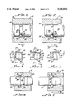
- FIG. 8 shows an alternative embodiment 100 which includes a cylindrical body, or a piston, 102 disposed within a housing 104.
- a groove 106 in the piston 102 includes a tapered bottom for supporting a spring 110.
- a radial detent 112 in the housing 104 includes ramp portions 116, 118 on each side thereof to facilitate assembly and connecting of the piston 102 with the housing 104 in both directions, as indicated by the arrows 120, 122.
- FIG. 9 shows yet another embodiment 126, in accordance with the present invention, generally showing a piston 128 within a housing 130 with a groove 132 having a tapered bottom 136, or a flat bottom, not shown, for receiving a spring 138 and holding 126 to body 12.
- a ramp portion 140 on the housing 130 facilitates assembly of the piston 128 within the housing 130.
- the embodiment 146 shown in FIGS. 10, 11 and 12, enables a piston 148 to be connected and locked in both directions within a housing 150.
- this term means that the piston 148 is locked in one direction but can be disconnected in the opposite direction and, by switching the position of a spring 152 within a groove 154, having two tapered surfaces 158, 160 connect and lock can be achieved in the opposite direction.
- a locked position is indicated by the arrows 162, 164; and the unlocked position is indicated by the arrows 166, 168.
- the tapered surfaces 158, 160 join respective groove side walls 172, 174 at angles B, C which are acute.
- locking action can be achieved in one direction, as shown by the arrows 162, 164 or in the opposite direction, as indicated by the arrows 166, 168.
- FIG. 13 there is yet another embodiment 180 in accordance with the present invention, which provides a snap-on fastening connection between a cylindrical member 182 and a housing plate 184.
- the cylindrical member 182 and plate 184 are held together by means of a canted-coil spring 190.
- the member 182 may be cylindrical although means of fabrication to other geometries, such as rectangular or elliptical shape (not shown), may be utilized.
- the spring 190 may be mounted in the piston in a circular pattern as shown or in the housing.
- a tapered bottom 194 in the circumferential groove 192 prevents a spring 190 from rotating past a line 191 perpendicular to the cylindrical body axis in order to prevent disassembly of the cylindrical body 182 from the plate 184.
- the plate 184 has a selected thickness and an opening 193 therein with a diameter greater than the diameter of the end portion 182A and smaller than the body 182 diameter for receiving the end portion 182A with the spring protruding, as shown in FIG. 13, from the circumferential groove 192 on a side 197 of the plate 184 opposite another side 199 of the plate 184 facing the cylindrical body 182.
- FIG. 15 there is shown an enlarged view of the end portion 182A showing the spring 190 in a fully assembled position.
- the groove 192 in the member 182 includes a tapered bottom 194.
- the tapered groove 192 permits substantially a greater degree of flexibility in assembly and the angle of the taper influences such flexibility as hereinabove noted. After the assembly takes place, it is necessary that the spring have sufficient force to snap inward or outward and create the actual locking action that keeps the member 182 and the plate 184 together.
- an outward groove side wall 198 may disposed at an angle ⁇ for the purpose of preventing the spring 190 from vibrating out of the groove 192 and further provide a greater degree of reliability of performance.
- the spring 190 may be sized so that it is compressed in a manner that the coils will butt or nearly butt to provide for effective electromagnetic shielding and improved electrical conductivity between the member 182 and plate 184 as well as provide improved thermal dissipation and environmental sealing. In this configuration, destruction of the spring 190 may be necessary in order to separate the member 182 from the plate 184.
- FIG. 18 is a view similar to FIG. 17 showing the spring 190 in a compressed or butted position with respect to the plate 184 and the end portion 182A, thereby preventing disassembly of the plate 184 from the cylindrical body 182.
- FIG. 19 is another alternative snap-on fastener mechanism 180A which includes a cylindrical body 182A with an end portion 182B with a groove 192A fastening, with housing 184A having a bore 193A with a groove 193B therein.
- the snap-on fastening operation is similar to that described in connection with the fastener 180 shown in FIG. 14.
- FIG. 20 is a view similar to FIG. 19 with the cylinder 182A in engagement with the housing 184A.
- FIG. 21 shows a view of the embodiment 180A with the spring 190 disposed in the groove 193B, having a tapered bottom 194A.
- FIG. 22 is a view similar to that shown in FIG. 21 with the groove 193B having a flat bottom 194B.
- FIG. 23 is a view similar to that shown in FIG. 22 in which the spring 190 is compressed, or butted, thereby preventing disassembly of the cylindrical body 182A from the housing 184A.
- Environmental sealing may be enhanced for any of the hereinabove described embodiments by filling springs 236, 238, 240 with elastomer 242, 244, 246, as shown in FIGS. 26a-28b.
- the elastomer may have a hollow center 248 or, as shown in FIG. 28a, the elastomer may have portions 250 protruding beyond the spring 240 along a minor axis 252 thereof.
- Canted-coil, elastomer-filled spring assemblies suitable for the present invention are taught in U.S. Pat. No. 5,161,806, as hereinabove noted, which is incorporated herewith by this specific reference thereto for teaching elastomer filled springs.
Abstract
Description
Claims (36)
Priority Applications (5)
| Application Number | Priority Date | Filing Date | Title |
|---|---|---|---|
| US08/143,913 US5545842A (en) | 1993-10-26 | 1993-10-26 | Radially mounted spring to connect, lock and unlock, and for snap-on fastening, and for mechanical, electromagnetic shielding, electrical conductivity, and thermal dissipation with environmental sealing |
| AT94116888T ATE153111T1 (en) | 1993-10-26 | 1994-10-26 | SPRING MECHANISM FOR CONNECTING, LOCKING AND UNLOCKING; SNAP CLOSURE FOR MECHANICAL AND ELECTROMAGNETIC SHIELDING, ELECTRICAL CONDUCTIVITY, THERMAL DISSIPATION WITH ENVIRONMENTAL SEALING |
| EP94116888A EP0649994B1 (en) | 1993-10-26 | 1994-10-26 | Radially mounted spring to connect, lock and unlock, hold snap-on fastening, and for mechanical, electromagnetic shielding, electrical conductivity, thermal dissipation with environmental sealing |
| DE69403172T DE69403172T2 (en) | 1993-10-26 | 1994-10-26 | Spring mechanism for connecting, locking and unlocking; Snap lock for mechanical and electromagnetic shielding, electrical conductivity, thermal dissipation with environmental sealing |
| JP6262919A JPH07174115A (en) | 1993-10-26 | 1994-10-26 | Assembling mechanism having environment-resistive sealing property, electromagnetic shielding property, conductivity and heat dissipating property |
Applications Claiming Priority (1)
| Application Number | Priority Date | Filing Date | Title |
|---|---|---|---|
| US08/143,913 US5545842A (en) | 1993-10-26 | 1993-10-26 | Radially mounted spring to connect, lock and unlock, and for snap-on fastening, and for mechanical, electromagnetic shielding, electrical conductivity, and thermal dissipation with environmental sealing |
Publications (1)
| Publication Number | Publication Date |
|---|---|
| US5545842A true US5545842A (en) | 1996-08-13 |
Family
ID=22506235
Family Applications (1)
| Application Number | Title | Priority Date | Filing Date |
|---|---|---|---|
| US08/143,913 Expired - Lifetime US5545842A (en) | 1993-10-26 | 1993-10-26 | Radially mounted spring to connect, lock and unlock, and for snap-on fastening, and for mechanical, electromagnetic shielding, electrical conductivity, and thermal dissipation with environmental sealing |
Country Status (5)
| Country | Link |
|---|---|
| US (1) | US5545842A (en) |
| EP (1) | EP0649994B1 (en) |
| JP (1) | JPH07174115A (en) |
| AT (1) | ATE153111T1 (en) |
| DE (1) | DE69403172T2 (en) |
Cited By (86)
| Publication number | Priority date | Publication date | Assignee | Title |
|---|---|---|---|---|
| US5716160A (en) * | 1995-02-28 | 1998-02-10 | Samsung Heavy Industries | Mounting device for cushion plunger in hydraulic cylinder |
| US5808534A (en) * | 1996-07-30 | 1998-09-15 | Laffey; James | Solenoid frame and method of manufacture |
| EP0890758A2 (en) | 1997-07-07 | 1999-01-13 | Bal Seal Engineering Company, Inc. | Radial and axial springs with coils canting along the major axis |
| US20030094812A1 (en) * | 2001-11-21 | 2003-05-22 | Balsells Peter J. | Connector with radial spring |
| US20030096526A1 (en) * | 2001-11-21 | 2003-05-22 | Balsells Peter J. | Connector for latching and carrying current capabilities with tooless connection |
| US20030204262A1 (en) * | 2002-04-30 | 2003-10-30 | Ferguson Joe William | Quick disconnect orthopaedic trials |
| US20040124635A1 (en) * | 2002-09-18 | 2004-07-01 | Checkfluid Inc. | Removable Quick Connection |
| US20040175229A1 (en) * | 2003-02-18 | 2004-09-09 | Pete Balsells | Spring holding connectors |
| US20040215302A1 (en) * | 2003-04-25 | 2004-10-28 | Sage Shahn S. | Electrical connectors for medical lead having weld-less wiring connection |
| US20040215303A1 (en) * | 2003-04-25 | 2004-10-28 | Sage Shahn S. | Implantable biomedical electrical connectors having integral side and inner walls |
| US20040245686A1 (en) * | 2003-06-04 | 2004-12-09 | Balsells Peter J. | Spring latching connectors radially and axially mounted |
| US20050234521A1 (en) * | 2004-04-16 | 2005-10-20 | Balsells Peter J | Use of an axial canted coil spring as an electrical contact to minimize resistivity variations under dynamic loads |
| US20050242910A1 (en) * | 2004-04-29 | 2005-11-03 | Balsells Peter J | Contact assembly |
| US20060012134A1 (en) * | 2004-07-15 | 2006-01-19 | Temper Corporation | Mounting rings for shafts |
| US20060228166A1 (en) * | 2005-04-05 | 2006-10-12 | Bal Seal Engineering Co., Inc. | Ball holding, latching and locking applications using radial and axial springs |
| US20060270286A1 (en) * | 2005-05-25 | 2006-11-30 | Weiping Zhao | Canted coil spring power terminal and sequence connection system |
| US20060270277A1 (en) * | 2005-05-25 | 2006-11-30 | Weiping Zhao | Canted coil spring power terminal and sequence connection system |
| US20070042648A1 (en) * | 2005-05-19 | 2007-02-22 | Bal Seal Engineering Co., Inc. | Electrical connector with embedded canted coil spring |
| US20070066152A1 (en) * | 2004-03-30 | 2007-03-22 | Kostal Kontakt Systeme Gmbh | Electrical socket contact for high current applications |
| US20080078880A1 (en) * | 2006-09-29 | 2008-04-03 | Airbus Uk Limited | Aircraft fuel pipe coupling |
| US20080106040A1 (en) * | 2006-08-10 | 2008-05-08 | Zielke Clyde R | Multimember Extended Range Compressible Seal |
| US20080254670A1 (en) * | 2007-04-13 | 2008-10-16 | Balsells Peter J | Electrical connectors with improved electrical contact performance |
| US20090039728A1 (en) * | 2004-04-29 | 2009-02-12 | Balsells Peter J | Contact assembly |
| US20090076333A1 (en) * | 2007-09-17 | 2009-03-19 | Levahn Intellectual Property Holding Company, Llc | Flip Control Retractor Support |
| US20090149053A1 (en) * | 2007-12-06 | 2009-06-11 | Changsrivong Derek | In-line connector |
| US20090160139A1 (en) * | 2007-12-21 | 2009-06-25 | Balsells Pete J | Locking mechanism with quick disassembly means |
| CN100585199C (en) * | 2005-04-05 | 2010-01-27 | 巴尔密封工程有限公司 | Use ball maintenance, locking bolt and the locking device of radial and axial spring |
| US20100029145A1 (en) * | 2008-07-30 | 2010-02-04 | Pete Balsells | Canted coil multi-metallic wire |
| WO2010030897A2 (en) | 2008-09-15 | 2010-03-18 | Bal Seal Engineering | Apparatus including a pin connector for securing a first member and a second member to one another, and associated methods |
| US20100090379A1 (en) * | 2003-06-04 | 2010-04-15 | Balsells Peter J | Spring latching connectors |
| EP2198489A1 (en) * | 2007-10-10 | 2010-06-23 | Bal Seal Engineering Company, Inc. | Ball holding,latching and locking applications using radial and axial springs by incorporating eletrical conductivity and electrical switchings |
| US20100216337A1 (en) * | 2009-02-24 | 2010-08-26 | Charles Dudley Copper | Electrical connector with slider component for fault condition connection |
| US20100216355A1 (en) * | 2009-02-24 | 2010-08-26 | Charles Dudley Copper | Electrical bushing with radial interposer spring |
| US20100216354A1 (en) * | 2009-02-24 | 2010-08-26 | Charles Dudley Copper | Electrical bushing with helper spring to apply force to contact spring |
| US20100224400A1 (en) * | 2009-03-06 | 2010-09-09 | Saint-Gobain Performance Plastics Corporation | Overlap helical conductive spring |
| US20100289198A1 (en) * | 2009-04-28 | 2010-11-18 | Pete Balsells | Multilayered canted coil springs and associated methods |
| US20100304622A1 (en) * | 2007-12-05 | 2010-12-02 | Mitsubishi Electric Corporation | Contact device |
| US20110079962A1 (en) * | 2009-10-02 | 2011-04-07 | Saint-Gobain Performance Plastics Corporation | Modular polymeric emi/rfi seal |
| US20110124245A1 (en) * | 2008-04-14 | 2011-05-26 | Mitsubishi Electric Corporation | Contact |
| US20110190833A1 (en) * | 2010-01-29 | 2011-08-04 | Medtronic, Inc. | Header assembly for implantable medical device |
| US20110244714A1 (en) * | 2008-12-12 | 2011-10-06 | Tyco Electronics Amp Gmbh | High-current plug-in connector |
| EP2458231A1 (en) | 2010-11-30 | 2012-05-30 | Bal Seal Engineering Co. | Multi-stage engagement assemblies and related methods |
| EP2469659A2 (en) | 2010-12-23 | 2012-06-27 | Bal Seal Engineering, Inc. | Electrical connector with a canted coil spring |
| US20120301248A1 (en) * | 2011-05-25 | 2012-11-29 | Nuvasive, Inc. | System and Method for Fastening Objects Together |
| US8382532B2 (en) | 2010-05-13 | 2013-02-26 | Bal Seal Engineering, Inc. | Insert element engaging a canted coil spring disposed in a groove in a bore formed by two housing parts |
| US8428724B2 (en) | 2011-03-11 | 2013-04-23 | Greatbatch Ltd. | Low insertion force electrical connector for implantable medical devices |
| US20140053639A1 (en) * | 2011-04-25 | 2014-02-27 | Waters Technologies Corporation | Fitting Assemblies |
| EP2228496A3 (en) * | 2009-03-09 | 2014-06-04 | Hansa Metallwerke AG | Electric actuation device for a sanitary fitting |
| US20140179148A1 (en) * | 2012-12-21 | 2014-06-26 | Bal Seal Engineering, Inc. | Locking connectors and related methods |
| US8790819B1 (en) * | 2006-10-06 | 2014-07-29 | Greatbatch Ltd. | Implantable medical assembly |
| US8858272B2 (en) | 2009-12-10 | 2014-10-14 | Robert Bosch Gmbh | High current contact and corresponding method for producing a high current contact assembly |
| US9124141B2 (en) | 2009-06-26 | 2015-09-01 | Mitsubishi Heavy Industries, Ltd. | Wireless power transmission system |
| US9192419B2 (en) | 2008-11-07 | 2015-11-24 | DePuy Synthes Products, Inc. | Zero-profile interbody spacer and coupled plate assembly |
| US9220604B2 (en) | 2010-12-21 | 2015-12-29 | DePuy Synthes Products, Inc. | Intervertebral implants, systems, and methods of use |
| US9220548B2 (en) | 2003-09-03 | 2015-12-29 | DePuy Synthes Products, Inc. | Bone plate with captive clips |
| US9241809B2 (en) | 2010-12-21 | 2016-01-26 | DePuy Synthes Products, Inc. | Intervertebral implants, systems, and methods of use |
| US9308380B2 (en) | 2011-12-28 | 2016-04-12 | Cardiac Pacemakers, Inc. | Toroidal compressible element including a switchback pattern |
| US9408646B2 (en) | 2003-09-03 | 2016-08-09 | DePuy Synthes Products, Inc. | Bone plate with captive clips |
| US9414870B2 (en) | 2003-09-03 | 2016-08-16 | DePuy Synthes Products, Inc. | Translatable carriage fixation system |
| US9463097B2 (en) | 2003-02-06 | 2016-10-11 | DePuy Synthes Products, Inc. | Intervertebral implant |
| US9572681B2 (en) | 2002-02-19 | 2017-02-21 | DePuy Synthes Products, Inc. | Intervertebral implant |
| US9744049B2 (en) | 2007-11-16 | 2017-08-29 | DePuy Synthes Products, Inc. | Low profile intervertebral implant |
| US9806473B2 (en) | 2015-01-08 | 2017-10-31 | Bal Seal Engineering, Inc. | High frequency miniature connectors with canted coil springs and related methods |
| US9829028B2 (en) | 2012-11-15 | 2017-11-28 | Bal Seal Engineering, Inc. | Connectors with a pin, a housing, and one or more springs |
| US9867718B2 (en) | 2014-10-22 | 2018-01-16 | DePuy Synthes Products, Inc. | Intervertebral implants, systems, and methods of use |
| US9882332B2 (en) | 2012-11-30 | 2018-01-30 | Bal Seal Engineering, Inc. | Spring connectors with adjustable grooves and related methods |
| CN107702909A (en) * | 2017-10-30 | 2018-02-16 | 天津市汇点机电设备开发有限公司 | Quick-locking device |
| US10151368B2 (en) | 2014-05-02 | 2018-12-11 | Bal Seal Engineering, Inc. | Nested canted coil springs, applications thereof, and related methods |
| US10181668B2 (en) | 2016-06-24 | 2019-01-15 | Bal Seal Engineering, Inc. | Spring contacts and related methods |
| EP3456428A1 (en) | 2017-08-30 | 2019-03-20 | Bal Seal Engineering, Inc. | Spring wire ends to facilitate welding |
| US10263368B2 (en) | 2013-06-25 | 2019-04-16 | Bal Seal Engineering, Inc. | Electrical contacts with electrically conductive springs |
| US10263379B2 (en) | 2017-03-24 | 2019-04-16 | Bal Seal Engineering, Inc. | Large deflection canted coil springs, connectors, and related methods |
| US10270198B2 (en) | 2014-09-15 | 2019-04-23 | Bal Seal Engineering, Inc. | Canted coil springs, connectors and related methods |
| US10288203B2 (en) | 2014-03-26 | 2019-05-14 | Nelson Products, Inc. | Latching connector with radial grooves |
| US10361528B2 (en) | 2012-09-14 | 2019-07-23 | Bal Seal Engineering, Inc. | Connector housings, use of, and method therefor |
| US10512548B2 (en) | 2006-02-27 | 2019-12-24 | DePuy Synthes Products, Inc. | Intervertebral implant with fixation geometry |
| US10520001B2 (en) | 2015-03-13 | 2019-12-31 | Bal Seal Engineering, Inc. | Stamped housings to facilitate assembly and related methods |
| DE102018005359A1 (en) | 2018-07-05 | 2020-01-09 | Mtconnectivity Power2Pcb Gmbh | Contact element with a printed circuit board |
| US10598241B2 (en) | 2014-02-26 | 2020-03-24 | Bal Seal Engineering, Inc. | Multi deflection canted coil springs and related methods |
| DE202020000697U1 (en) | 2020-02-19 | 2020-06-02 | Mtconnectivity Power2Pcb Gmbh | Contact device |
| US10935097B2 (en) | 2013-03-14 | 2021-03-02 | Bal Seal Engineering, Llc | Canted coil spring with longitudinal component within and related methods |
| US10965055B2 (en) | 2016-06-24 | 2021-03-30 | Bal Seal Engineering, Llc | Connectors and related methods |
| US11050190B2 (en) | 2016-06-02 | 2021-06-29 | Bal Seal Engineering, Llc | Electrical connectors with linear springs and related methods |
| US11162326B2 (en) | 2017-05-02 | 2021-11-02 | Weatherford Technology Holdings, Llc | Actuator assembly |
| US11235374B2 (en) | 2012-11-13 | 2022-02-01 | Bal Seal Engineering, Llc | Canted coil springs and assemblies and related methods |
| EP4075609A1 (en) | 2021-04-15 | 2022-10-19 | Tc1 Llc | Systems and methods for medical device connectors |
Families Citing this family (10)
| Publication number | Priority date | Publication date | Assignee | Title |
|---|---|---|---|---|
| US6259849B1 (en) * | 1999-04-29 | 2001-07-10 | Litton Systems, Inc. | Rapid assembly and disassembly O-ring instrument mount for fiber optic gyroscopes |
| FR2864688B1 (en) * | 2003-12-29 | 2006-02-24 | Alstom | ELECTRICAL CONTACT DEVICE FOR MEDIUM OR HIGH VOLTAGE ELECTRICAL EQUIPMENT, METHOD AND APPARATUS THEREFOR. |
| DE102004002404B3 (en) * | 2004-01-16 | 2005-09-08 | Tyco Electronics Amp Gmbh | Spring element for contact tube or jack e.g. for electrical pluggable connections, has spring element with linear base section having curved contact tongues along both long sides |
| DE102004002403B3 (en) * | 2004-01-16 | 2005-07-14 | Tyco Electronics Amp Gmbh | Spring element, especially for contact socket, has contact tongues each consisting of two separate strips with cut-out between them and strips are connected together with radius at their outer and inner ends |
| US8382533B2 (en) | 2010-07-02 | 2013-02-26 | Lear Corporation | Electrically conducting terminal |
| JP5444542B2 (en) * | 2010-08-26 | 2014-03-19 | 株式会社富永製作所 | Emergency shut-off device for lubrication equipment |
| US10634181B2 (en) * | 2013-03-12 | 2020-04-28 | Case Western Reserve University | Asymmetrical-force connector system |
| DE102016211256A1 (en) | 2016-06-23 | 2017-12-28 | Zf Friedrichshafen Ag | Contact system, circuit board assembly and connector assembly |
| SE540889C2 (en) * | 2017-02-14 | 2018-12-11 | Azelio Ab | A fastener and a fastening element for securing a mirror to a support of a parabolic solar reflector |
| CN113277126B (en) * | 2021-05-24 | 2022-07-12 | 北京科技大学 | Space docking mechanism based on electromagnetic type ball lock structure |
Citations (20)
| Publication number | Priority date | Publication date | Assignee | Title |
|---|---|---|---|---|
| US4655462A (en) * | 1985-01-07 | 1987-04-07 | Peter J. Balsells | Canted coiled spring and seal |
| US4826144A (en) * | 1988-04-25 | 1989-05-02 | Peter J. Balsells | Inside back angle canted coil spring |
| US4830344A (en) * | 1988-04-25 | 1989-05-16 | Peter J. Balsells | Canted-coil spring with turn angle and seal |
| US4876781A (en) * | 1988-04-25 | 1989-10-31 | Peter J. Balsells | Method of making a garter-type axially resilient coiled spring |
| US4893795A (en) * | 1988-08-15 | 1990-01-16 | Peter J. Balsells | Radially loaded canted coiled spring with turn angle |
| US4907788A (en) * | 1988-04-25 | 1990-03-13 | Peter J. Balsells | Dual concentric canted-coil spring apparatus |
| US4915366A (en) * | 1988-04-25 | 1990-04-10 | Peter J. Balsells | Outside back angle canted coil spring |
| US4934666A (en) * | 1988-04-25 | 1990-06-19 | Peter J. Balsells | Coiled spring electromagnetic shielding gasket |
| US4961253A (en) * | 1988-04-25 | 1990-10-09 | Peter J. Balsells | Manufacturing method for canted-coil spring with turn angle and seal |
| US4964204A (en) * | 1988-04-25 | 1990-10-23 | Peter J. Balsells | Method for making a garter-type axially-resilient coil spring |
| US4974821A (en) * | 1988-04-25 | 1990-12-04 | Peter J. Balsells | Canted-coil spring with major axis radial loading |
| US5072070A (en) * | 1989-12-01 | 1991-12-10 | Peter J. Balsells | Device for sealing electromagnetic waves |
| US5079388A (en) * | 1989-12-01 | 1992-01-07 | Peter J. Balsells | Gasket for sealing electromagnetic waves |
| US5108078A (en) * | 1988-04-25 | 1992-04-28 | Peter J. Balsells | Canted-coil spring loaded while in a cavity |
| US5117066A (en) * | 1988-04-25 | 1992-05-26 | Peter J. Balsells | Retaining and locking electromagnetic gasket |
| US5134244A (en) * | 1988-04-25 | 1992-07-28 | Peter J. Balsells | Electromagnetic shielding seal for rotary/reciprocating shaft |
| US5160122A (en) * | 1990-03-20 | 1992-11-03 | Peter J. Balsells | Coil spring with an elastomer having a hollow coil cross section |
| US5161806A (en) * | 1990-12-17 | 1992-11-10 | Peter J. Balsells | Spring-loaded, hollow, elliptical ring seal |
| US5203849A (en) * | 1990-03-20 | 1993-04-20 | Balsells Peter J | Canted coil spring in length filled with an elastomer |
| US5411348A (en) * | 1993-10-26 | 1995-05-02 | Bal Seal Engineering Company, Inc. | Spring mechanism to connect, lock and unlock, members |
Family Cites Families (5)
| Publication number | Priority date | Publication date | Assignee | Title |
|---|---|---|---|---|
| US2615735A (en) * | 1949-12-27 | 1952-10-28 | Waldes Kohinoor Inc | Spring retaining ring for machine parts |
| DE1075898B (en) * | 1956-09-14 | 1960-02-18 | Agfa Ag | Device for the detachable connection of device parts |
| DE3227431A1 (en) * | 1982-02-01 | 1983-08-11 | Fa. Aug. Winkhaus, 4404 Telgte | Fastening of a locking element of a building fitted to an associated carrier |
| DE4040337C2 (en) * | 1990-12-17 | 1998-09-10 | Schaeffler Waelzlager Ohg | Axial locking of two components that can be moved against each other |
| US5082390A (en) * | 1991-01-22 | 1992-01-21 | Peter J. Balsells | Latching, holding and locking spring apparatus |
-
1993
- 1993-10-26 US US08/143,913 patent/US5545842A/en not_active Expired - Lifetime
-
1994
- 1994-10-26 AT AT94116888T patent/ATE153111T1/en not_active IP Right Cessation
- 1994-10-26 JP JP6262919A patent/JPH07174115A/en active Pending
- 1994-10-26 EP EP94116888A patent/EP0649994B1/en not_active Expired - Lifetime
- 1994-10-26 DE DE69403172T patent/DE69403172T2/en not_active Expired - Lifetime
Patent Citations (20)
| Publication number | Priority date | Publication date | Assignee | Title |
|---|---|---|---|---|
| US4655462A (en) * | 1985-01-07 | 1987-04-07 | Peter J. Balsells | Canted coiled spring and seal |
| US4974821A (en) * | 1988-04-25 | 1990-12-04 | Peter J. Balsells | Canted-coil spring with major axis radial loading |
| US5117066A (en) * | 1988-04-25 | 1992-05-26 | Peter J. Balsells | Retaining and locking electromagnetic gasket |
| US4964204A (en) * | 1988-04-25 | 1990-10-23 | Peter J. Balsells | Method for making a garter-type axially-resilient coil spring |
| US4826144A (en) * | 1988-04-25 | 1989-05-02 | Peter J. Balsells | Inside back angle canted coil spring |
| US4907788A (en) * | 1988-04-25 | 1990-03-13 | Peter J. Balsells | Dual concentric canted-coil spring apparatus |
| US4915366A (en) * | 1988-04-25 | 1990-04-10 | Peter J. Balsells | Outside back angle canted coil spring |
| US4934666A (en) * | 1988-04-25 | 1990-06-19 | Peter J. Balsells | Coiled spring electromagnetic shielding gasket |
| US4961253A (en) * | 1988-04-25 | 1990-10-09 | Peter J. Balsells | Manufacturing method for canted-coil spring with turn angle and seal |
| US4876781A (en) * | 1988-04-25 | 1989-10-31 | Peter J. Balsells | Method of making a garter-type axially resilient coiled spring |
| US5134244A (en) * | 1988-04-25 | 1992-07-28 | Peter J. Balsells | Electromagnetic shielding seal for rotary/reciprocating shaft |
| US4830344A (en) * | 1988-04-25 | 1989-05-16 | Peter J. Balsells | Canted-coil spring with turn angle and seal |
| US5108078A (en) * | 1988-04-25 | 1992-04-28 | Peter J. Balsells | Canted-coil spring loaded while in a cavity |
| US4893795A (en) * | 1988-08-15 | 1990-01-16 | Peter J. Balsells | Radially loaded canted coiled spring with turn angle |
| US5072070A (en) * | 1989-12-01 | 1991-12-10 | Peter J. Balsells | Device for sealing electromagnetic waves |
| US5079388A (en) * | 1989-12-01 | 1992-01-07 | Peter J. Balsells | Gasket for sealing electromagnetic waves |
| US5160122A (en) * | 1990-03-20 | 1992-11-03 | Peter J. Balsells | Coil spring with an elastomer having a hollow coil cross section |
| US5203849A (en) * | 1990-03-20 | 1993-04-20 | Balsells Peter J | Canted coil spring in length filled with an elastomer |
| US5161806A (en) * | 1990-12-17 | 1992-11-10 | Peter J. Balsells | Spring-loaded, hollow, elliptical ring seal |
| US5411348A (en) * | 1993-10-26 | 1995-05-02 | Bal Seal Engineering Company, Inc. | Spring mechanism to connect, lock and unlock, members |
Cited By (183)
| Publication number | Priority date | Publication date | Assignee | Title |
|---|---|---|---|---|
| US5716160A (en) * | 1995-02-28 | 1998-02-10 | Samsung Heavy Industries | Mounting device for cushion plunger in hydraulic cylinder |
| US5808534A (en) * | 1996-07-30 | 1998-09-15 | Laffey; James | Solenoid frame and method of manufacture |
| EP0890758A2 (en) | 1997-07-07 | 1999-01-13 | Bal Seal Engineering Company, Inc. | Radial and axial springs with coils canting along the major axis |
| US6749358B2 (en) | 2001-11-21 | 2004-06-15 | Bal Seal Engineering Co., Inc. | Connector for latching and carrying current capabilities with tooless connection |
| US20030096526A1 (en) * | 2001-11-21 | 2003-05-22 | Balsells Peter J. | Connector for latching and carrying current capabilities with tooless connection |
| US8375543B1 (en) * | 2001-11-21 | 2013-02-19 | Bal Seal Engineering, Inc. | Method for controlling connect and disconnect forces of a connector |
| US8297662B2 (en) | 2001-11-21 | 2012-10-30 | Bal Seal Engineering, Inc. | Method for controlling connect and disconnect forces of a connector |
| US20100028076A1 (en) * | 2001-11-21 | 2010-02-04 | Balsells Peter J | Method for controlling connect and disconnect forces of a connector |
| US20030094812A1 (en) * | 2001-11-21 | 2003-05-22 | Balsells Peter J. | Connector with radial spring |
| US8561274B2 (en) | 2001-11-21 | 2013-10-22 | Bal Seal Engineering, Inc. | Method for controlling connect and disconnect forces of a connector |
| US8166623B2 (en) * | 2001-11-21 | 2012-05-01 | Bal Seal Engineering, Inc. | Method for controlling connect and disconnect forces of a connector |
| US10492922B2 (en) | 2002-02-19 | 2019-12-03 | DePuy Synthes Products, Inc. | Intervertebral implant |
| US9572681B2 (en) | 2002-02-19 | 2017-02-21 | DePuy Synthes Products, Inc. | Intervertebral implant |
| US20030204262A1 (en) * | 2002-04-30 | 2003-10-30 | Ferguson Joe William | Quick disconnect orthopaedic trials |
| US20040124635A1 (en) * | 2002-09-18 | 2004-07-01 | Checkfluid Inc. | Removable Quick Connection |
| US10064740B2 (en) | 2003-02-06 | 2018-09-04 | DePuy Synthes Products, LLC | Intervertebral implant |
| US9463097B2 (en) | 2003-02-06 | 2016-10-11 | DePuy Synthes Products, Inc. | Intervertebral implant |
| US10660765B2 (en) | 2003-02-06 | 2020-05-26 | DePuy Synthes Products, Inc. | Intervertebral implant |
| WO2004074669A3 (en) * | 2003-02-18 | 2005-06-09 | Bal Seal Eng Co Inc | Spring holding connectors |
| US20040175229A1 (en) * | 2003-02-18 | 2004-09-09 | Pete Balsells | Spring holding connectors |
| US20060127170A1 (en) * | 2003-02-18 | 2006-06-15 | Pete Balsells | Spring holding connectors |
| US20040215303A1 (en) * | 2003-04-25 | 2004-10-28 | Sage Shahn S. | Implantable biomedical electrical connectors having integral side and inner walls |
| US7110827B2 (en) | 2003-04-25 | 2006-09-19 | Medtronic, Inc. | Electrical connectors for medical lead having weld-less wiring connection |
| US20040215302A1 (en) * | 2003-04-25 | 2004-10-28 | Sage Shahn S. | Electrical connectors for medical lead having weld-less wiring connection |
| US8078280B2 (en) | 2003-04-25 | 2011-12-13 | Medtronic, Inc. | Implantable biomedical electrical connectors having integral side and inner walls |
| US20190003509A1 (en) * | 2003-06-04 | 2019-01-03 | Bal Seal Engineering, Inc. | Spring latching connectors |
| WO2004109859A2 (en) | 2003-06-04 | 2004-12-16 | Bal Seal Engineering Co., Inc. | Spring latching connectors radially and axially mounted |
| US10767679B2 (en) | 2003-06-04 | 2020-09-08 | Bal Seal Engineering, Llc | Spring latching connectors |
| US10655665B2 (en) * | 2003-06-04 | 2020-05-19 | Bal Seal Engineering, Inc. | Spring latching connectors |
| US20040245686A1 (en) * | 2003-06-04 | 2004-12-09 | Balsells Peter J. | Spring latching connectors radially and axially mounted |
| US8167285B2 (en) | 2003-06-04 | 2012-05-01 | Bal Seal Engineering Co., Inc. | Spring latching connectors radially and axially mounted |
| US20170314602A1 (en) * | 2003-06-04 | 2017-11-02 | Bal Seal Engineering, Inc. | Spring latching connectors |
| US11035397B2 (en) | 2003-06-04 | 2021-06-15 | Bal Seal Engineering, Llc | Spring latching connectors |
| US9534625B2 (en) | 2003-06-04 | 2017-01-03 | Bal Seal Engineering, Inc. | Spring latching connectors |
| US20100090379A1 (en) * | 2003-06-04 | 2010-04-15 | Balsells Peter J | Spring latching connectors |
| US9267526B2 (en) * | 2003-06-04 | 2016-02-23 | Bal Seal Engineering, Inc. | Spring latching connectors |
| US9408646B2 (en) | 2003-09-03 | 2016-08-09 | DePuy Synthes Products, Inc. | Bone plate with captive clips |
| US9414870B2 (en) | 2003-09-03 | 2016-08-16 | DePuy Synthes Products, Inc. | Translatable carriage fixation system |
| US10368927B2 (en) | 2003-09-03 | 2019-08-06 | DePuy Synthes Products, Inc. | Bone plate with captive clips |
| US9220548B2 (en) | 2003-09-03 | 2015-12-29 | DePuy Synthes Products, Inc. | Bone plate with captive clips |
| US20070066152A1 (en) * | 2004-03-30 | 2007-03-22 | Kostal Kontakt Systeme Gmbh | Electrical socket contact for high current applications |
| US7241189B2 (en) | 2004-03-30 | 2007-07-10 | Kostal Kontakt Systeme Gmbh | High-current terminal blade type connector |
| US20050234521A1 (en) * | 2004-04-16 | 2005-10-20 | Balsells Peter J | Use of an axial canted coil spring as an electrical contact to minimize resistivity variations under dynamic loads |
| US7274964B2 (en) * | 2004-04-16 | 2007-09-25 | Bal Seal Engineering Co., Inc. | Use of an axial canted coil spring as an electrical contact to minimize resistivity variations under dynamic loads |
| US20090039728A1 (en) * | 2004-04-29 | 2009-02-12 | Balsells Peter J | Contact assembly |
| US20050242910A1 (en) * | 2004-04-29 | 2005-11-03 | Balsells Peter J | Contact assembly |
| WO2005112055A3 (en) * | 2004-04-29 | 2006-01-19 | Bal Seal Eng Co Inc | Contact assembly |
| US9150226B2 (en) | 2004-07-15 | 2015-10-06 | Amsted Rail Company, Inc. | Mounting ring |
| US8607431B2 (en) | 2004-07-15 | 2013-12-17 | John E. Rode | Ring for mounting a structure to a shaft |
| US20090258714A1 (en) * | 2004-07-15 | 2009-10-15 | Temper Corporation | Mounting ring |
| US9016746B2 (en) | 2004-07-15 | 2015-04-28 | Temper Axle Products Corporation | Train axle assembly |
| US8657299B2 (en) * | 2004-07-15 | 2014-02-25 | John E. Rode | Mounting rings for shafts |
| US8317202B2 (en) | 2004-07-15 | 2012-11-27 | Rode John E | Method of mounting a structure to a shaft |
| US20060012134A1 (en) * | 2004-07-15 | 2006-01-19 | Temper Corporation | Mounting rings for shafts |
| US8662557B2 (en) | 2004-07-15 | 2014-03-04 | John E Rode | Train axle assembly |
| US20090258715A1 (en) * | 2004-07-15 | 2009-10-15 | Temper Corporation | Method of mounting a structure to a shaft |
| CN100585199C (en) * | 2005-04-05 | 2010-01-27 | 巴尔密封工程有限公司 | Use ball maintenance, locking bolt and the locking device of radial and axial spring |
| WO2006107789A3 (en) * | 2005-04-05 | 2007-05-24 | Bal Seal Eng Co Inc | Ball holding, latching and locking applications using radial and axial springs |
| US20060228166A1 (en) * | 2005-04-05 | 2006-10-12 | Bal Seal Engineering Co., Inc. | Ball holding, latching and locking applications using radial and axial springs |
| WO2006107789A2 (en) | 2005-04-05 | 2006-10-12 | Bal Seal Engineering Co., Inc. | Ball holding, latching and locking applications using radial and axial springs |
| US7316593B2 (en) * | 2005-05-19 | 2008-01-08 | Bal Seal Engineering Co., Inc. | Electrical connector with embedded canted coil spring |
| CN101223674B (en) * | 2005-05-19 | 2010-09-29 | 巴尔密封工程公司 | Electrical connector with embedded canted coil spring |
| US20070042648A1 (en) * | 2005-05-19 | 2007-02-22 | Bal Seal Engineering Co., Inc. | Electrical connector with embedded canted coil spring |
| WO2006124969A3 (en) * | 2005-05-19 | 2007-12-21 | Bal Seal Eng Co Inc | Electrical connector with embedded canted coil spring |
| US20070232154A1 (en) * | 2005-05-25 | 2007-10-04 | Weiping Zhao | Canted coil spring power terminal and sequence connection system |
| US20060270277A1 (en) * | 2005-05-25 | 2006-11-30 | Weiping Zhao | Canted coil spring power terminal and sequence connection system |
| US7294020B2 (en) * | 2005-05-25 | 2007-11-13 | Alcoa Fujikura Ltd. | Canted coil spring power terminal and sequence connection system |
| US20060270286A1 (en) * | 2005-05-25 | 2006-11-30 | Weiping Zhao | Canted coil spring power terminal and sequence connection system |
| US7229327B2 (en) * | 2005-05-25 | 2007-06-12 | Alcoa Fujikura Limited | Canted coil spring power terminal and sequence connection system |
| US7458862B2 (en) | 2005-05-25 | 2008-12-02 | Alcoa Fujikura Ltd. | Canted coil spring power terminal and sequence connection system |
| US10512548B2 (en) | 2006-02-27 | 2019-12-24 | DePuy Synthes Products, Inc. | Intervertebral implant with fixation geometry |
| US11696837B2 (en) | 2006-02-27 | 2023-07-11 | DePuy Synthes Products, Inc. | Intervertebral implant with fixation geometry |
| US20080106040A1 (en) * | 2006-08-10 | 2008-05-08 | Zielke Clyde R | Multimember Extended Range Compressible Seal |
| US20080078880A1 (en) * | 2006-09-29 | 2008-04-03 | Airbus Uk Limited | Aircraft fuel pipe coupling |
| US8790819B1 (en) * | 2006-10-06 | 2014-07-29 | Greatbatch Ltd. | Implantable medical assembly |
| US20080254670A1 (en) * | 2007-04-13 | 2008-10-16 | Balsells Peter J | Electrical connectors with improved electrical contact performance |
| US7914351B2 (en) | 2007-04-13 | 2011-03-29 | Bal Seal Engineering | Electrical connectors with improved electrical contact performance |
| US20090076333A1 (en) * | 2007-09-17 | 2009-03-19 | Levahn Intellectual Property Holding Company, Llc | Flip Control Retractor Support |
| EP2198489A1 (en) * | 2007-10-10 | 2010-06-23 | Bal Seal Engineering Company, Inc. | Ball holding,latching and locking applications using radial and axial springs by incorporating eletrical conductivity and electrical switchings |
| EP2198489A4 (en) * | 2007-10-10 | 2014-09-24 | Bal Seal Eng Co Inc | Ball holding,latching and locking applications using radial and axial springs by incorporating eletrical conductivity and electrical switchings |
| US9744049B2 (en) | 2007-11-16 | 2017-08-29 | DePuy Synthes Products, Inc. | Low profile intervertebral implant |
| US10137003B2 (en) | 2007-11-16 | 2018-11-27 | DePuy Synthes Products, Inc. | Low profile intervertebral implant |
| US10543102B2 (en) | 2007-11-16 | 2020-01-28 | DePuy Synthes Products, Inc. | Low profile intervertebral implant |
| US8057270B2 (en) * | 2007-12-05 | 2011-11-15 | Mitsubishi Electric Corporation | Contact device |
| US20100304622A1 (en) * | 2007-12-05 | 2010-12-02 | Mitsubishi Electric Corporation | Contact device |
| US7722415B2 (en) * | 2007-12-06 | 2010-05-25 | Bal Seal Engineering, Inc. | In-line connector |
| WO2009076310A2 (en) | 2007-12-06 | 2009-06-18 | Bal Seal Engineering | In-line connector |
| US20100199493A1 (en) * | 2007-12-06 | 2010-08-12 | Derek Chansrivong | In-line connector |
| US20090149053A1 (en) * | 2007-12-06 | 2009-06-11 | Changsrivong Derek | In-line connector |
| US7955145B2 (en) | 2007-12-06 | 2011-06-07 | Bal Seal Engineering, Inc. | In-line connector |
| US8308167B2 (en) * | 2007-12-21 | 2012-11-13 | Bal Seal Engineering, Inc. | Locking mechanism with quick disassembly means |
| US20090160139A1 (en) * | 2007-12-21 | 2009-06-25 | Balsells Pete J | Locking mechanism with quick disassembly means |
| US7999202B2 (en) * | 2008-04-14 | 2011-08-16 | Mitsubishi Electric Corporation | Contact |
| US20110124245A1 (en) * | 2008-04-14 | 2011-05-26 | Mitsubishi Electric Corporation | Contact |
| US9293849B2 (en) | 2008-07-30 | 2016-03-22 | Bal Seal Engineering, Inc. | Electrical connector using a canted coil multi-metallic wire |
| US20100029145A1 (en) * | 2008-07-30 | 2010-02-04 | Pete Balsells | Canted coil multi-metallic wire |
| US20100064490A1 (en) * | 2008-09-15 | 2010-03-18 | Pete Balsells | Apparatus including a pin connector for securing a first member and a second member to one another, and associated methods |
| WO2010030897A2 (en) | 2008-09-15 | 2010-03-18 | Bal Seal Engineering | Apparatus including a pin connector for securing a first member and a second member to one another, and associated methods |
| US8196271B2 (en) * | 2008-09-15 | 2012-06-12 | Bal Seal Engineering, Inc. | Apparatus including a pin connector for securing a first member and a second member to one another, and associated methods |
| US9414935B2 (en) | 2008-11-07 | 2016-08-16 | DePuy Synthes Products, Inc. | Zero-profile interbody spacer and coupled plate assembly |
| US11612492B2 (en) | 2008-11-07 | 2023-03-28 | DePuy Synthes Products, Inc. | Zero-profile interbody spacer and coupled plate assembly |
| US10531960B2 (en) | 2008-11-07 | 2020-01-14 | DePuy Synthes Products, Inc. | Zero-profile interbody spacer and coupled plate assembly |
| US10433976B2 (en) | 2008-11-07 | 2019-10-08 | DePuy Synthes Products, Inc. | Zero-profile interbody spacer and coupled plate assembly |
| US9192419B2 (en) | 2008-11-07 | 2015-11-24 | DePuy Synthes Products, Inc. | Zero-profile interbody spacer and coupled plate assembly |
| US11517444B2 (en) | 2008-11-07 | 2022-12-06 | DePuy Synthes Products, Inc. | Zero-profile interbody spacer and coupled plate assembly |
| US9402735B2 (en) | 2008-11-07 | 2016-08-02 | DePuy Synthes Products, Inc. | Zero-profile interbody spacer and coupled plate assembly |
| US8337240B2 (en) * | 2008-12-12 | 2012-12-25 | Tyco Electronics Amp Gmbh | High-current plug-in connector |
| US20110244714A1 (en) * | 2008-12-12 | 2011-10-06 | Tyco Electronics Amp Gmbh | High-current plug-in connector |
| US7942682B2 (en) | 2009-02-24 | 2011-05-17 | Tyco Electronics Corporation | Electrical connector with slider component for fault condition connection |
| US7837519B2 (en) | 2009-02-24 | 2010-11-23 | Tyco Electronics Corporation | Electrical bushing with helper spring to apply force to contact spring |
| US7942683B2 (en) | 2009-02-24 | 2011-05-17 | Tyco Electronics Corporation | Electrical bushing with radial interposer spring |
| US20100216355A1 (en) * | 2009-02-24 | 2010-08-26 | Charles Dudley Copper | Electrical bushing with radial interposer spring |
| US20100216354A1 (en) * | 2009-02-24 | 2010-08-26 | Charles Dudley Copper | Electrical bushing with helper spring to apply force to contact spring |
| US20100216337A1 (en) * | 2009-02-24 | 2010-08-26 | Charles Dudley Copper | Electrical connector with slider component for fault condition connection |
| US20100224400A1 (en) * | 2009-03-06 | 2010-09-09 | Saint-Gobain Performance Plastics Corporation | Overlap helical conductive spring |
| EP2228496A3 (en) * | 2009-03-09 | 2014-06-04 | Hansa Metallwerke AG | Electric actuation device for a sanitary fitting |
| US20100289198A1 (en) * | 2009-04-28 | 2010-11-18 | Pete Balsells | Multilayered canted coil springs and associated methods |
| US9124141B2 (en) | 2009-06-26 | 2015-09-01 | Mitsubishi Heavy Industries, Ltd. | Wireless power transmission system |
| US20110079962A1 (en) * | 2009-10-02 | 2011-04-07 | Saint-Gobain Performance Plastics Corporation | Modular polymeric emi/rfi seal |
| US8858272B2 (en) | 2009-12-10 | 2014-10-14 | Robert Bosch Gmbh | High current contact and corresponding method for producing a high current contact assembly |
| US9403022B2 (en) | 2010-01-29 | 2016-08-02 | Medtronic, Inc. | Header assembly for implantable medical device |
| US20110190833A1 (en) * | 2010-01-29 | 2011-08-04 | Medtronic, Inc. | Header assembly for implantable medical device |
| US8382532B2 (en) | 2010-05-13 | 2013-02-26 | Bal Seal Engineering, Inc. | Insert element engaging a canted coil spring disposed in a groove in a bore formed by two housing parts |
| EP3078865A1 (en) | 2010-11-30 | 2016-10-12 | Bal Seal Engineering, Inc. | Multi-stage engagement assemblies and related methods |
| US9500211B2 (en) | 2010-11-30 | 2016-11-22 | Bal Seal Engineering, Inc. | Multi-stage engagement assemblies and related methods |
| US9004805B2 (en) * | 2010-11-30 | 2015-04-14 | Bal Seal Engineering, Inc. | Multi-stage engagement assemblies and related methods |
| US20120134742A1 (en) * | 2010-11-30 | 2012-05-31 | Bal Seal Engineering, Inc. | Multi-stage engagement assemblies and related methods |
| EP2458231A1 (en) | 2010-11-30 | 2012-05-30 | Bal Seal Engineering Co. | Multi-stage engagement assemblies and related methods |
| US9241809B2 (en) | 2010-12-21 | 2016-01-26 | DePuy Synthes Products, Inc. | Intervertebral implants, systems, and methods of use |
| US9848992B2 (en) | 2010-12-21 | 2017-12-26 | DePuy Synthes Products, Inc. | Intervertebral implants, systems, and methods of use |
| US10507117B2 (en) | 2010-12-21 | 2019-12-17 | DePuy Synthes Products, Inc. | Intervertebral implants, systems, and methods of use |
| US11458027B2 (en) | 2010-12-21 | 2022-10-04 | DePuy Synthes Products, Inc. | Intervertebral implants, systems, and methods of use |
| US9220604B2 (en) | 2010-12-21 | 2015-12-29 | DePuy Synthes Products, Inc. | Intervertebral implants, systems, and methods of use |
| EP2469659A2 (en) | 2010-12-23 | 2012-06-27 | Bal Seal Engineering, Inc. | Electrical connector with a canted coil spring |
| US8844126B2 (en) | 2010-12-23 | 2014-09-30 | Bal Seal Engineering, Inc. | Method of manufacturing an electrical connector |
| US8934974B2 (en) | 2011-03-11 | 2015-01-13 | Greatbatch Ltd. | Low insertion force electrical connector for implantable medical devices |
| US8428724B2 (en) | 2011-03-11 | 2013-04-23 | Greatbatch Ltd. | Low insertion force electrical connector for implantable medical devices |
| US9037243B2 (en) | 2011-03-11 | 2015-05-19 | Greatbatch Ltd. | Low insertion force electrical connector for implantable medical devices |
| US9618483B2 (en) * | 2011-04-25 | 2017-04-11 | Waters Technologies Corporation | Fitting assemblies |
| US20140053639A1 (en) * | 2011-04-25 | 2014-02-27 | Waters Technologies Corporation | Fitting Assemblies |
| US20120301248A1 (en) * | 2011-05-25 | 2012-11-29 | Nuvasive, Inc. | System and Method for Fastening Objects Together |
| US9308380B2 (en) | 2011-12-28 | 2016-04-12 | Cardiac Pacemakers, Inc. | Toroidal compressible element including a switchback pattern |
| US10226635B2 (en) | 2011-12-28 | 2019-03-12 | Cardiac Pacemakers, Inc. | Toroidal compressible element including a switchback pattern |
| US10361528B2 (en) | 2012-09-14 | 2019-07-23 | Bal Seal Engineering, Inc. | Connector housings, use of, and method therefor |
| US11296475B2 (en) | 2012-09-14 | 2022-04-05 | Bal Seal Engineering, Llc | Connector housings, use of, and method therefor |
| US11235374B2 (en) | 2012-11-13 | 2022-02-01 | Bal Seal Engineering, Llc | Canted coil springs and assemblies and related methods |
| US9829028B2 (en) | 2012-11-15 | 2017-11-28 | Bal Seal Engineering, Inc. | Connectors with a pin, a housing, and one or more springs |
| US9882332B2 (en) | 2012-11-30 | 2018-01-30 | Bal Seal Engineering, Inc. | Spring connectors with adjustable grooves and related methods |
| US10447000B2 (en) | 2012-11-30 | 2019-10-15 | Bal Seal Engineering, Inc. | Spring connectors with adjustable grooves and related methods |
| US9312630B2 (en) * | 2012-12-21 | 2016-04-12 | Bal Seal Engineering, Inc. | Locking connectors and related methods |
| US20140179148A1 (en) * | 2012-12-21 | 2014-06-26 | Bal Seal Engineering, Inc. | Locking connectors and related methods |
| US10935097B2 (en) | 2013-03-14 | 2021-03-02 | Bal Seal Engineering, Llc | Canted coil spring with longitudinal component within and related methods |
| US10847935B2 (en) | 2013-06-25 | 2020-11-24 | Bal Seal Engineering, Llc | Electrical contacts with electrically conductive springs |
| US10263368B2 (en) | 2013-06-25 | 2019-04-16 | Bal Seal Engineering, Inc. | Electrical contacts with electrically conductive springs |
| US10598241B2 (en) | 2014-02-26 | 2020-03-24 | Bal Seal Engineering, Inc. | Multi deflection canted coil springs and related methods |
| US10288203B2 (en) | 2014-03-26 | 2019-05-14 | Nelson Products, Inc. | Latching connector with radial grooves |
| US10151368B2 (en) | 2014-05-02 | 2018-12-11 | Bal Seal Engineering, Inc. | Nested canted coil springs, applications thereof, and related methods |
| US10837511B2 (en) | 2014-05-02 | 2020-11-17 | Bal Seal Engineering, Llc | Nested canted coil springs, applications thereof, and related methods |
| US10535945B2 (en) | 2014-09-15 | 2020-01-14 | Bal Seal Engineering, Inc. | Canted coil springs, connectors and related methods |
| US10270198B2 (en) | 2014-09-15 | 2019-04-23 | Bal Seal Engineering, Inc. | Canted coil springs, connectors and related methods |
| US11540927B2 (en) | 2014-10-22 | 2023-01-03 | DePuy Synthes Products, Inc. | Intervertebral implants, systems, and methods of use |
| US10130492B2 (en) | 2014-10-22 | 2018-11-20 | DePuy Synthes Products, Inc. | Intervertebral implants, systems, and methods of use |
| US10010432B2 (en) | 2014-10-22 | 2018-07-03 | DePuy Synthes Products, Inc. | Intervertebral implants, systems, and methods of use |
| US10702394B2 (en) | 2014-10-22 | 2020-07-07 | DePuy Synthes Products, Inc. | Intervertebral implants, systems, and methods of use |
| US9867718B2 (en) | 2014-10-22 | 2018-01-16 | DePuy Synthes Products, Inc. | Intervertebral implants, systems, and methods of use |
| US10348042B2 (en) | 2015-01-08 | 2019-07-09 | Bal Seal Engineering, Inc. | High frequency miniature connectors with canted coil springs and related methods |
| US9806473B2 (en) | 2015-01-08 | 2017-10-31 | Bal Seal Engineering, Inc. | High frequency miniature connectors with canted coil springs and related methods |
| US10520001B2 (en) | 2015-03-13 | 2019-12-31 | Bal Seal Engineering, Inc. | Stamped housings to facilitate assembly and related methods |
| US11204054B2 (en) * | 2015-03-13 | 2021-12-21 | Bal Seal Engineering, Llc | Stamped housings to facilitate assembly and related methods |
| US11598361B2 (en) * | 2015-03-13 | 2023-03-07 | Bal Seal Engineering, LLP | Stamped housings to facilitate assembly and related methods |
| US20220034349A1 (en) * | 2015-03-13 | 2022-02-03 | Bal Seal Engineering, Llc | Stamped housings to facilitate assembly and related methods |
| US11050190B2 (en) | 2016-06-02 | 2021-06-29 | Bal Seal Engineering, Llc | Electrical connectors with linear springs and related methods |
| US10181668B2 (en) | 2016-06-24 | 2019-01-15 | Bal Seal Engineering, Inc. | Spring contacts and related methods |
| US10965055B2 (en) | 2016-06-24 | 2021-03-30 | Bal Seal Engineering, Llc | Connectors and related methods |
| US10263379B2 (en) | 2017-03-24 | 2019-04-16 | Bal Seal Engineering, Inc. | Large deflection canted coil springs, connectors, and related methods |
| US11162326B2 (en) | 2017-05-02 | 2021-11-02 | Weatherford Technology Holdings, Llc | Actuator assembly |
| EP3456428A1 (en) | 2017-08-30 | 2019-03-20 | Bal Seal Engineering, Inc. | Spring wire ends to facilitate welding |
| US10900531B2 (en) | 2017-08-30 | 2021-01-26 | Bal Seal Engineering, Llc | Spring wire ends to faciliate welding |
| CN107702909A (en) * | 2017-10-30 | 2018-02-16 | 天津市汇点机电设备开发有限公司 | Quick-locking device |
| DE102018005359A1 (en) | 2018-07-05 | 2020-01-09 | Mtconnectivity Power2Pcb Gmbh | Contact element with a printed circuit board |
| DE102018005359B4 (en) * | 2018-07-05 | 2020-03-12 | Mtconnectivity Power2Pcb Gmbh | Contact element with a printed circuit board |
| DE202020000697U1 (en) | 2020-02-19 | 2020-06-02 | Mtconnectivity Power2Pcb Gmbh | Contact device |
| EP4075609A1 (en) | 2021-04-15 | 2022-10-19 | Tc1 Llc | Systems and methods for medical device connectors |
Also Published As
| Publication number | Publication date |
|---|---|
| EP0649994A1 (en) | 1995-04-26 |
| ATE153111T1 (en) | 1997-05-15 |
| JPH07174115A (en) | 1995-07-11 |
| DE69403172T2 (en) | 1998-01-08 |
| EP0649994B1 (en) | 1997-05-14 |
| DE69403172D1 (en) | 1997-06-19 |
Similar Documents
| Publication | Publication Date | Title |
|---|---|---|
| US5545842A (en) | Radially mounted spring to connect, lock and unlock, and for snap-on fastening, and for mechanical, electromagnetic shielding, electrical conductivity, and thermal dissipation with environmental sealing | |
| US5411348A (en) | Spring mechanism to connect, lock and unlock, members | |
| US8167285B2 (en) | Spring latching connectors radially and axially mounted | |
| US10655665B2 (en) | Spring latching connectors | |
| US4334730A (en) | Insulated from ground bulkhead adapter | |
| US5082390A (en) | Latching, holding and locking spring apparatus | |
| EP0629113B1 (en) | Gasket assembly for sealing electromagnetic waves | |
| KR19980070863A (en) | Sealed electrical connector assembly | |
| US11158962B2 (en) | Terminal cover | |
| US4936791A (en) | Environmental seal means for plug and socket connector assembly | |
| WO1998045902A1 (en) | Panel mount connector with twist lock | |
| US5277623A (en) | Low profile panel mountable retainer for electrical connectors | |
| CN1308397A (en) | Member connector and connection method | |
| EP0890758A2 (en) | Radial and axial springs with coils canting along the major axis | |
| US20200259293A1 (en) | Anti-vibration connector and method for assembling the same | |
| US20040192120A1 (en) | Plug connector for connection with a battery terminal | |
| US4225799A (en) | Field magnet assembly | |
| US10587062B2 (en) | Housing post for an electrical assembly | |
| US10541493B1 (en) | Flexing mounting clip for an electrical assembly | |
| US20240055848A1 (en) | Cable fastening system for electrical connector assembly | |
| KR102474967B1 (en) | Nut locking system and electronic device comprising such nut locking system | |
| US20020192995A1 (en) | Positive locking element lead retainer/insulator | |
| JP3257919B2 (en) | Retainer type connector | |
| KR20240013074A (en) | Shield contact element and method of manufacturing such a shield contact element | |
| JPH0212689Y2 (en) |
Legal Events
| Date | Code | Title | Description |
|---|---|---|---|
| AS | Assignment |
Owner name: BAL SEAL ENGINEERING CO., INC., CALIFORNIA Free format text: ASSIGNMENT OF ASSIGNORS INTEREST;ASSIGNOR:BALSELLS, PETER J.;REEL/FRAME:006755/0156 Effective date: 19931018 |
|
| STCF | Information on status: patent grant |
Free format text: PATENTED CASE |
|
| FEPP | Fee payment procedure |
Free format text: PAYOR NUMBER ASSIGNED (ORIGINAL EVENT CODE: ASPN); ENTITY STATUS OF PATENT OWNER: SMALL ENTITY |
|
| FPAY | Fee payment |
Year of fee payment: 4 |
|
| FPAY | Fee payment |
Year of fee payment: 8 |
|
| FEPP | Fee payment procedure |
Free format text: PAT HOLDER NO LONGER CLAIMS SMALL ENTITY STATUS, ENTITY STATUS SET TO UNDISCOUNTED (ORIGINAL EVENT CODE: STOL); ENTITY STATUS OF PATENT OWNER: SMALL ENTITY |
|
| FEPP | Fee payment procedure |
Free format text: PAT HOLDER CLAIMS SMALL ENTITY STATUS, ENTITY STATUS SET TO SMALL (ORIGINAL EVENT CODE: LTOS); ENTITY STATUS OF PATENT OWNER: SMALL ENTITY |
|
| FPAY | Fee payment |
Year of fee payment: 12 |
|
| REMI | Maintenance fee reminder mailed |