US5710536A - Adaptive coil wrap apparatus - Google Patents
Adaptive coil wrap apparatus Download PDFInfo
- Publication number
- US5710536A US5710536A US08/601,553 US60155396A US5710536A US 5710536 A US5710536 A US 5710536A US 60155396 A US60155396 A US 60155396A US 5710536 A US5710536 A US 5710536A
- Authority
- US
- United States
- Prior art keywords
- conductors
- flexible base
- terminal
- terminals
- coil
- Prior art date
- Legal status (The legal status is an assumption and is not a legal conclusion. Google has not performed a legal analysis and makes no representation as to the accuracy of the status listed.)
- Expired - Fee Related
Links
Images


Classifications
-
- C—CHEMISTRY; METALLURGY
- C02—TREATMENT OF WATER, WASTE WATER, SEWAGE, OR SLUDGE
- C02F—TREATMENT OF WATER, WASTE WATER, SEWAGE, OR SLUDGE
- C02F1/00—Treatment of water, waste water, or sewage
- C02F1/48—Treatment of water, waste water, or sewage with magnetic or electric fields
- C02F1/484—Treatment of water, waste water, or sewage with magnetic or electric fields using electromagnets
- C02F1/485—Treatment of water, waste water, or sewage with magnetic or electric fields using electromagnets located on the outer wall of the treatment device, i.e. not in contact with the liquid to be treated, e.g. detachable
-
- A—HUMAN NECESSITIES
- A61—MEDICAL OR VETERINARY SCIENCE; HYGIENE
- A61N—ELECTROTHERAPY; MAGNETOTHERAPY; RADIATION THERAPY; ULTRASOUND THERAPY
- A61N1/00—Electrotherapy; Circuits therefor
- A61N1/18—Applying electric currents by contact electrodes
- A61N1/20—Applying electric currents by contact electrodes continuous direct currents
- A61N1/205—Applying electric currents by contact electrodes continuous direct currents for promoting a biological process
-
- C—CHEMISTRY; METALLURGY
- C02—TREATMENT OF WATER, WASTE WATER, SEWAGE, OR SLUDGE
- C02F—TREATMENT OF WATER, WASTE WATER, SEWAGE, OR SLUDGE
- C02F2201/00—Apparatus for treatment of water, waste water or sewage
- C02F2201/48—Devices for applying magnetic or electric fields
- C02F2201/483—Devices for applying magnetic or electric fields using coils
-
- C—CHEMISTRY; METALLURGY
- C02—TREATMENT OF WATER, WASTE WATER, SEWAGE, OR SLUDGE
- C02F—TREATMENT OF WATER, WASTE WATER, SEWAGE, OR SLUDGE
- C02F2303/00—Specific treatment goals
- C02F2303/22—Eliminating or preventing deposits, scale removal, scale prevention
Definitions
- This invention relates to an improvement in the field of coils, as for example the solenoid coil used for electronic descaling wherein fluids are treated by exposure to magnetic and electric fields.
- Coils for generating electric and magnetic fields are useful in many applications. For example, problems caused by hard water such as scale deposits of dissolved minerals on the interior surfaces of pipes, are treated by exposing hard water to magnetic fields.
- An energized solenoid cable wrapped around a pipe for the purpose of treating fluids within the pipe with electrical and magnetic fields is known from U.S. Pat. Nos. 5,074,998, 5,171,431, 4,326,954, 2,596,743 and 3,843,507.
- any of the above cited patents show an energized coil wrapped around a pipe for the purpose of exposing fluids within the pipe to electric and magnetic fields. Solenoid coils are also useful in other fields, such the automotive field to generate linear motion to engage the electric starter to the gasoline engine.
- Solenoid coils are further useful in the medical field to treat blood or living tissue.
- a coil is shown consisting of a multi-conductor ribbon cable with offset connectors to form an inductor.
- the present invention is embodied in a solenoid coil comprising a substantially parallel plurality of conductors on a flexible base. First ends of each of the plurality of conductors are connected together. Second ends of each of the plurality of conductors are connected together.
- the flexible base is wound around a water pipe, bodypart or the like.
- An alignment mechanism is provided to substantially align a first level of parallel conductors to the next level of parallel conductors above the first level.
- the first level need not be directly on top of the lower level, but the two levels can be offset, so long as the alignment provides a fixed relationship between conductors on the first and second levels.
- An input terminal is coupled to one end of each of the plurality conductors, while an output terminal is coupled to the other end of each of the substantially plurality conductors.
- a coil is thus formed around the pipe.
- a power supply is coupled to the input terminal and the output terminal to provide current through each of the parallel conductors.
- Each wrap of the flexible base provides a number of conductor turns equal to the number of parallel conductors.
- the substantial alignment each of the parallel conductors with the corresponding conductor above and below, carries current in the same direction around the pipe. As a result, the magnetic and electric fields generated are additive to produce a desired field within the water pipe.
- a substantially parallel first plurality of conductors and a substantially parallel second plurality of conductors are disposed on a flexible base.
- First ends of the first plurality of conductors are connected together and coupled to a first terminal of said first plurality of conductors.
- First ends of the second plurality of conductors are connected together and coupled to a first terminal of said second plurality of conductors.
- Second ends of the first plurality of conductors are connected together and coupled to a second terminal of said first plurality of conductors.
- Second ends of the second plurality of conductors are connected together and coupled to a second terminal of said second plurality of conductors.
- a return conductor is provided on the flexible base to connect the second terminal of said first plurality of conductors to the first terminal of said second plurality of conductors.
- An input terminal is coupled to the first terminal of said first plurality conductors, while an output terminal is coupled to the second terminal of said second plurality of conductors.
- a coil is thus formed around the pipe.
- a power supply is coupled to the input terminal and the output terminal to provide current through each of the first plurality of conductors, and, via the return conductor, through each of the second plurality of conductors.
- Each wrap of the flexible base provides a number of conductor turns equal to the number of parallel conductors. Also, the substantial alignment each of the conductors with its own corresponding respective conductor above and below the current turn around the pipe, provides collinear unidirectional current carried in the same direction around the pipe. As a result, the magnetic and electric fields generated are additive to produce a desired field within the water pipe.
- the return conductor provides a reverse field relative to the additive field generated by the first plurality of parallel conductors and the second plurality of parallel conductors.
- the return conductor is disposed up flow (i.e., upstream) from the first and second plurality of conductors. Since the return conductors are placed upstream from the first plurality of conductors, destructive interference with the desired additive field within the water pipe is prevented.
- a coil formed with the adaptive coil apparatus of the present invention requires fewer hand turns to form, since multiple conductors are wrapped at the same time.
- the adaptive coil apparatus will conform to the pipe diameter, and have the proper spacing between the individual wires and successive layers.
- the flexible base and alignment device assures that coil will fit pipes of any diameter.
- FIG. 1 is a block diagram of a system embodying a solenoid coil in accordance with the prior art for used in an electronic descaling system.
- FIG. 2 is an illustration of a flexible circuit for forming a coil, in accordance with the present invention.
- FIG. 3 is a schematic diagram of a flexible circuit for forming a coil, in accordance with the present invention.
- FIG. 4 is an isometric view of a coil forming apparatus positioned around a support in accordance with the present invention.
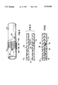
- FIG. 5 is a crossectional view of an alignment device for use in conjunction with the present invention.
- FIG. 6 is crossectional view of an alignment device positioned to align conductors for use in conjunction with the present invention.
- FIG. 7 is crossectional view of a fluid carrying pipe and a coil forming apparatus in accordance with the present invention.
- FIG. 8 is an illustration of a flexible circuit for forming a coil, in accordance with a second embodiment of the present invention.
- FIG. 9 is crossectional view of a fluid carrying pipe and a coil forming apparatus in accordance with a second embodiment of the present invention.
- FIG. 1 A conventional coil, or solenoid as for use in an electronic water treatment apparatus, is shown in FIG. 1.
- Coil 12 is wrapped around a water pipe 14.
- a power supply 10, coupled to the AC line, provides appropriate current to the coil.
- the field generated by the coil 12 inside the pipe 14 treats input water flow 16 to affect electronic descaling in the output water flow 18.
- coil 12 is installed around an existing water pipe. Accordingly, coil 12 is installed by hand, wrapping it one turn at a time around pipe 14, and connecting power supply 10 via terminals 11 and 13. To remove the coil 12, the power supply 10 is disconnected at terminals 11 and 13, and the coil 12 unwrapped one turn at a time by hand.
- a coil wrap apparatus 20 in accordance with the present invention is shown in FIG. 2.
- a plurality of parallel conductors 26A, 26B, 26C and 26B are coupled between input terminal 22 and output terminal 24.
- the parallel conductors 26A, 26B, 26C and 26B are formed on or within a flexible base (reference numeral 30 in FIG. 4), such as for example, a plastic sheet material of the type used for flexible printed circuits.
- the flexible base may also be the insulation of a ribbon cable of the type used to encapsulate wires for interconnections in electronic equipment.
- FIG. 3 A schematic diagram of the coil wrap apparatus 20 is shown in FIG. 3.
- Each of the parallel conductors 26A, 26B, 26C and 26B is represented by a resistor R1.
- the coupling between parallel conductors is represented by a resistor R1, and the coupling between the parallel conductors to the input terminal, and to output terminal, respectively by a respective resistor R3.
- the coil wrap apparatus 20 is preferably symmetrical between input and output so that the total impedance between the input terminal 22 and the output terminal 24 through each respective parallel conductor 26A, 26B, 26C and 26B should be equal. If so, the input current between terminal 22 and 24 is more or less equally divided.
- the resistive impedance through parallel conductor 26A (ignoring the other parallel conductors) from input terminal 22 to output terminal 24 is 2R3+3R1+R2.
- the resistive impedance from input to output through conductor 26B is the same, as is the resistive impedance from input to output through conductors 26C and 26D. Accordingly, an input current of 10 amperes will be approximately equally divided into 2.5 amperes in each of parallel conductors 26A, 26B, 26C and 26B.
- An alternative to symmetrical construction is to trim a portion of the width of each parallel conductor in the manufacturing process so as to control the total path resistance. For this purpose, the lower resistance paths may be increased by laser trimming a portion of each path at a site on the flexible base provided for this purpose.
- the coil wrap apparatus is shown installed around a pipe 14 in FIG. 4.
- the flexible base 30 is bent to conform to the surface of pipe 14.
- Successive turns around the pipe are layered to align the conductors 26A, 26B, 26C and 26D over prior turns.
- An device to achieve alignment between successive turns is shown in FIG. 5 and 6.
- Conductor 32 and 34 are successive turns of the same one of the parallel conductors, as is base 36 and 38 successive turns of the same flexible base. Alignment is effected by protrusion 40 on the bottom surface of the flexible base 30, and a recess 42 on the top surface of the flexible base 30. Both the protrusion 40 and recess 42 are longitudinal formations along the entire length of flexible base 30.
- the linear alignment device shown may be used with any diameter pipe.
- protrusion 40 When protrusion 40 seats into recess 42, the conductors 32 and 34 are aligned vertically with respect to one another. Internal ridges 44 in the recess 42 act to retain protrusion 40 in recess 42, and to provide a positive sound and feel when proper alignment is achieved.
- FIG. 7 A crossectional view of coil 20 installed on a water pipe 14 is shown in FIG. 7.
- Flexible base 30 provides two complete turns around the pipe.
- the first turn of conductors 26A, 26B, 26C and 26D are aligned with respect to the second turn of the respective conductors.
- the active area of the coil is region 23 between the conductors 26A and 26D at the extremities of adaptive coil wrap apparatus.
- An energizing current between input terminal 22 and output terminal 24 provides a field within pipe 14.
- the flexible base and alignment device assures that a coil will be properly formed, with proper spacing between the individual wires and layers.
- each of the parallel conductor is added to determine the total current requirement of the power supply. For a large number of parallel conductors, the current requirement increases.
- a second embodiment using more than one parallel plurality of conductors and current return conductors is shown in FIG. 8.
- An adaptive coil wrap apparatus in FIG. 8 has 24 parallel conductors and 5 current return conductors.
- the 24 parallel conductors are divided into 6 groups of 4 parallel conductors each.
- Three of the groups 50 consist of 3 sub-groups 92, 94 and 96.
- the other three groups 52 consist of 3 sub-groups 112, 114 and 116.
- Each of the sub-groups 92, 94, 96, 112, 114 and 116 consist of 4 substantially parallel conductors.
- the current return conductors 102, 104, 106, 108 and 110 connect the 6 groups in series between the input terminal 64 and the output terminal 62.
- first set of parallel conductors 92 are connected together at one end and coupled to input terminal 64.
- the other ends of parallel conductors 92 are connected together and coupled to current return conductor 102.
- a second set of parallel conductors 94 are connected together at one end and coupled to the other end of return conductor 102.
- the other ends of parallel conductors 94 are connected together and coupled to current return conductor 104.
- the third set of parallel conductors 96 are connected together at one end and coupled to the other end of return conductor 104. The other ends of parallel conductors 96 are connected together and coupled to current return conductor 106.
- a fourth set of parallel conductors 112 are connected together at one end and coupled to the other end of return conductor 106. The other ends of parallel conductors 112 are connected together and coupled to current return conductor 108.
- the fifth set of parallel conductors 114 are connected together at one end and coupled to the other end of return conductor 108. The other ends of parallel conductors 114 are connected together and coupled to current return conductor 110.
- a sixth set of parallel conductors 116 are connected together at one end and coupled to the other end of return conductor 110. The other ends of parallel conductors 116 are connected together and coupled to output terminal 62.
- the groups of parallel conductors 50, 52 and current return conductors 54 are formed on a flexible base with an alignment device.
- the coil is installed by wrapping successive turns around a support. Each successive layer has 24 conductors which are aligned with respect to the previous layer of the same 24 conductors to form the coil. Alignment may be directly over a prior turn, or offset slightly.
- the input current at terminal 64 is divided equally between the 4 substantially parallel conductors of the subgroup 92.
- the current through the parallel conductors of sub-group 92 is carried by current return conductor 102 to the sub-group 94 and so on, through each of the sub-groups in series to the last current return conductor 110 to sub-group 116 to output terminal 62.
- the total coil current 66 in one group 50 plus the total coil current 68 in the other group 52 equals the total return current 70 in the current return conductor 54.
- the region 60 is the active area of the coil forming a main field.
- the region 56 forms the area where the return current 70 forms a reverse field separated from the main field by a gap 58.
- the gap 58 is provided to separate the reverse field in region 56 from the main field in region 60.
- FIG. 9 A crossectional view of an adaptive coil wrap apparatus is shown in FIG. 9.
- the coil is installed on a water pipe 14.
- the main section of the coil has two groups 80, 82, each group having sub-groups, each sub-group having 4 substantially parallel conductors.
- the coil consists of 4 sub-groups which total 16 conductors, plus the 3 current return conductors 84. In general, the number of current return conductors will be one less (N-1) than the number (N) of sub-groups of parallel conductors.
- an energizing current between input terminal 72 and output terminal 74 provides a field within pipe 14.
- the active area of the coil is region 90 between the conductors at the extremities of adaptive coil wrap apparatus.
- the current in the return conductors 84 provides a reverse field in the region 86.
- a gap 88 is provided between the reverse field region 86 and the main field region 90.
- the reverse field region 86 is positioned up flow (i.e., upstream) from the conductors in region 90, so as to prevent destructive interference with the desired additive field within the water pipe. The further up stream that region 86 is positioned, the less the destructive interference with main coil region 90. However, the total coil resistance increases as the gap 88 increases. As a compromise between these competing parameters, the gap 88 from the main coil region 90 may be made equal to or larger than the width of the reverse field region 86.
- flexible base 81 is wound around the pipe 14. Two complete turns are shown but it will be appreciated that more turns are contemplated. With each successive wrap of the adaptive coil wrap apparatus, 16 conductors are wrapped at the same time. Each respective turn is aligned with the previous turn as previously indicated. The flexible base 81 and the alignnent device assures that a coil will be properly formed on the pipe 14, with proper spacing between the individual wires and layers.
Abstract
Description
Claims (8)
Priority Applications (1)
| Application Number | Priority Date | Filing Date | Title |
|---|---|---|---|
| US08/601,553 US5710536A (en) | 1996-02-14 | 1996-02-14 | Adaptive coil wrap apparatus |
Applications Claiming Priority (1)
| Application Number | Priority Date | Filing Date | Title |
|---|---|---|---|
| US08/601,553 US5710536A (en) | 1996-02-14 | 1996-02-14 | Adaptive coil wrap apparatus |
Publications (1)
| Publication Number | Publication Date |
|---|---|
| US5710536A true US5710536A (en) | 1998-01-20 |
Family
ID=24407939
Family Applications (1)
| Application Number | Title | Priority Date | Filing Date |
|---|---|---|---|
| US08/601,553 Expired - Fee Related US5710536A (en) | 1996-02-14 | 1996-02-14 | Adaptive coil wrap apparatus |
Country Status (1)
| Country | Link |
|---|---|
| US (1) | US5710536A (en) |
Cited By (20)
| Publication number | Priority date | Publication date | Assignee | Title |
|---|---|---|---|---|
| US6292085B1 (en) * | 1999-04-09 | 2001-09-18 | Electronic Descaling 2000, Inc. | Multiple coil assembly for use with electronic descaling unit |
| US20040000904A1 (en) * | 2002-06-28 | 2004-01-01 | Cotter James E. | Apparatus for detecting metal objects being put into a trash can |
| US20040099521A1 (en) * | 2002-11-13 | 2004-05-27 | Deka Products Limited Partnership | Liquid ring pumps with hermetically sealed motor rotors |
| US20050016828A1 (en) * | 2002-11-13 | 2005-01-27 | Deka Products Limited Partnership | Pressurized vapor cycle liquid distillation |
| US20050194048A1 (en) * | 2002-11-13 | 2005-09-08 | Deka Products Limited Partnership | Backpressure regulator |
| US20050238499A1 (en) * | 2002-11-13 | 2005-10-27 | Deka Products Limited Partnership | Fluid transfer using devices with rotatable housings |
| US20070017192A1 (en) * | 2002-11-13 | 2007-01-25 | Deka Products Limited Partnership | Pressurized vapor cycle liquid distillation |
| US20090038944A1 (en) * | 2007-08-10 | 2009-02-12 | Eric John Kruger | Fluid treatment device |
| US20110120870A1 (en) * | 2007-08-10 | 2011-05-26 | Eric John Kruger | Method and apparatus for treating a fluid |
| US20110147194A1 (en) * | 2008-08-15 | 2011-06-23 | Deka Products Limited Partnership | Water vending apparatus |
| US20110192179A1 (en) * | 2010-02-05 | 2011-08-11 | Freije Iii William F | Evaporative heat transfer system and method |
| US8006511B2 (en) | 2007-06-07 | 2011-08-30 | Deka Products Limited Partnership | Water vapor distillation apparatus, method and system |
| US8069676B2 (en) | 2002-11-13 | 2011-12-06 | Deka Products Limited Partnership | Water vapor distillation apparatus, method and system |
| US20120048593A1 (en) * | 2010-08-06 | 2012-03-01 | R&D Circuits, Inc. | Looped wire elastomeric contactor |
| US20130147590A1 (en) * | 2011-12-13 | 2013-06-13 | Finley Lee Ledbetter | Flexible magnetic field coil for measuring ionic quantity |
| US8511105B2 (en) | 2002-11-13 | 2013-08-20 | Deka Products Limited Partnership | Water vending apparatus |
| US9759773B2 (en) | 2011-12-13 | 2017-09-12 | Finley Lee Ledbetter | System and method to predict a usable life of a vacuum interrupter in the field |
| US11826681B2 (en) | 2006-06-30 | 2023-11-28 | Deka Products Limited Partneship | Water vapor distillation apparatus, method and system |
| US11885760B2 (en) | 2012-07-27 | 2024-01-30 | Deka Products Limited Partnership | Water vapor distillation apparatus, method and system |
| US11884555B2 (en) | 2007-06-07 | 2024-01-30 | Deka Products Limited Partnership | Water vapor distillation apparatus, method and system |
Citations (61)
| Publication number | Priority date | Publication date | Assignee | Title |
|---|---|---|---|---|
| FR525936A (en) * | 1920-05-04 | 1921-09-29 | App Electr Grivolas | Plug |
| GB278842A (en) * | 1926-08-13 | 1927-10-20 | Charles Oliver | Improvements in or relating to radio or high frequency choke coils for wireless telephony |
| US1732937A (en) * | 1929-10-22 | Transformer and coil system | ||
| US1960033A (en) * | 1931-12-05 | 1934-05-22 | Franklin S Smith | Transformer construction and method of making the same |
| US2355477A (en) * | 1942-10-15 | 1944-08-08 | William F Stahl | Form for windings and the like |
| US3108325A (en) * | 1961-01-13 | 1963-10-29 | Gen Dynamics Corp | Forming device |
| US3188591A (en) * | 1963-01-17 | 1965-06-08 | Ite Circuit Breaker Ltd | Transformer disk windings formed of a continuous conductor |
| US3195335A (en) * | 1962-12-07 | 1965-07-20 | Gen Dynamics Corp | Coil construction |
| US3278877A (en) * | 1964-05-15 | 1966-10-11 | Toko Inc | High frequency transformer having an improved q |
| US3321946A (en) * | 1964-12-16 | 1967-05-30 | Gen Motors Corp | Electromagnetic forming apparatus having improved backing member of high strength and electrical resistance |
| US3347074A (en) * | 1964-12-21 | 1967-10-17 | Gen Motors Corp | Electromagnetic forming apparatus and method |
| US3391558A (en) * | 1964-09-03 | 1968-07-09 | Siemens Ag | Device for magnetic-pulse forming of metallic workpieces |
| US3423978A (en) * | 1967-04-04 | 1969-01-28 | Gulf General Atomic Inc | Magnetic forming apparatus |
| US3486356A (en) * | 1967-05-19 | 1969-12-30 | Gulf General Atomic Inc | Forming apparatus and method |
| US3507034A (en) * | 1967-05-08 | 1970-04-21 | Nasa | Method and apparatus for precision sizing and joining of large diameter tubes |
| US3544940A (en) * | 1969-01-21 | 1970-12-01 | Hermetic Coil Co Inc | Inductor coil |
| US3602023A (en) * | 1969-02-07 | 1971-08-31 | Harold P Furth | Two piece magnetic swaging device |
| US3605055A (en) * | 1970-07-02 | 1971-09-14 | Gen Electric | Two-piece winding bobbin for watt-hour meter potential coil |
| US3654787A (en) * | 1968-10-15 | 1972-04-11 | Gulf Oil Corp | Electromagnetic forming apparatus |
| US3661342A (en) * | 1970-08-19 | 1972-05-09 | Jackson Controls Co Inc | Operative winding separator |
| US3689862A (en) * | 1971-01-20 | 1972-09-05 | Precision Paper Tube Co | Stackable coil form |
| US3810373A (en) * | 1971-05-24 | 1974-05-14 | Alusuisse | Machine for the magnetomotive forming of metallic objects |
| US3893462A (en) * | 1972-01-28 | 1975-07-08 | Esb Inc | Bioelectrochemical regenerator and stimulator devices and methods for applying electrical energy to cells and/or tissue in a living body |
| FR2309023A1 (en) * | 1975-04-23 | 1976-11-19 | Plessey Handel Investment Ag | INSULATING CASING FOR ELECTRIC WINDINGS |
| FR2326769A1 (en) * | 1975-10-01 | 1977-04-29 | Bosch Gmbh Robert | IC engines HV ignition coil compartmented former - has slots in compartment walls to accommodate interconnecting wires |
| US4039924A (en) * | 1975-12-29 | 1977-08-02 | General Electric Company | High voltage winding assembly with improved regulation |
| US4066065A (en) * | 1974-07-04 | 1978-01-03 | Werner Kraus | Coil structure for electromagnetic therapy |
| US4105017A (en) * | 1976-11-17 | 1978-08-08 | Electro-Biology, Inc. | Modification of the growth repair and maintenance behavior of living tissue and cells by a specific and selective change in electrical environment |
| US4266533A (en) * | 1976-11-17 | 1981-05-12 | Electro-Biology, Inc. | Modification of the growth, repair and maintenance behavior of living tissues and cells by a specific and selective change in electrical environment |
| US4313438A (en) * | 1979-07-16 | 1982-02-02 | Greatbatch W | Tissue growth control apparatus and method |
| US4315503A (en) * | 1976-11-17 | 1982-02-16 | Electro-Biology, Inc. | Modification of the growth, repair and maintenance behavior of living tissues and cells by a specific and selective change in electrical environment |
| US4421115A (en) * | 1977-09-22 | 1983-12-20 | Werner Kraus | Electrification attachment for an osteosynthesis implantate |
| US4442331A (en) * | 1981-01-22 | 1984-04-10 | Dai Ichi High Frequency Company, Ltd. | Method and apparatus of induction heating a metallic elongated material having different thickness sections |
| US4456001A (en) * | 1982-07-02 | 1984-06-26 | Electro-Biology, Inc. | Apparatus for equine hoof treatment |
| US4459988A (en) * | 1982-02-22 | 1984-07-17 | Biolectron, Inc. | Electrical stimulating apparatus |
| US4467808A (en) * | 1982-09-17 | 1984-08-28 | Biolectron, Inc. | Method for preventing and treating osteoporosis in a living body by using electrical stimulation non-invasively |
| US4467809A (en) * | 1982-09-17 | 1984-08-28 | Biolectron, Inc. | Method for non-invasive electrical stimulation of epiphyseal plate growth |
| US4501265A (en) * | 1982-12-23 | 1985-02-26 | Electro-Biology, Inc. | Applicator head for electromagnetic treatment of an afflicted body region |
| US4514712A (en) * | 1975-02-13 | 1985-04-30 | Mcdougal John A | Ignition coil |
| US4519394A (en) * | 1983-03-07 | 1985-05-28 | Trustees Of The University Of Pennsylvania | Method and apparatus for cathodic potential control in electrically induced osteogenesis |
| US4520360A (en) * | 1982-09-20 | 1985-05-28 | General Signal Corporation | Sensing vertical and horizontal visibility |
| US4527550A (en) * | 1983-01-28 | 1985-07-09 | The United States Of America As Represented By The Department Of Health And Human Services | Helical coil for diathermy apparatus |
| US4531393A (en) * | 1983-10-11 | 1985-07-30 | Maxwell Laboratories, Inc. | Electromagnetic forming apparatus |
| US4535775A (en) * | 1983-02-10 | 1985-08-20 | Biolectron, Inc. | Method for treatment of non-union bone fractures by non-invasive electrical stimulation |
| US4548208A (en) * | 1984-06-27 | 1985-10-22 | Medtronic, Inc. | Automatic adjusting induction coil treatment device |
| US4549547A (en) * | 1982-07-27 | 1985-10-29 | Trustees Of The University Of Pennsylvania | Implantable bone growth stimulator |
| US4550714A (en) * | 1983-03-09 | 1985-11-05 | Electro-Biology, Inc. | Electromagnetic coil insert for an orthopedic cast or the like |
| US4556051A (en) * | 1982-11-05 | 1985-12-03 | Empi, Inc. | Method and apparatus for healing tissue |
| US4561426A (en) * | 1984-02-29 | 1985-12-31 | Stewart David J | Magnetic biological device |
| US4672951A (en) * | 1985-12-30 | 1987-06-16 | Bio-Electric, Inc. | Method and apparatus for treatment of biological tissue |
| US4674482A (en) * | 1984-09-12 | 1987-06-23 | Irt, Inc. | Pulse electro-magnetic field therapy device with auto bias circuit |
| US4701830A (en) * | 1985-01-11 | 1987-10-20 | Fuji Electrochemical Co., Ltd. | Electronic circuit module |
| US4757804A (en) * | 1986-08-25 | 1988-07-19 | Lti Biomedical, Inc. | Device for electromagnetic treatment of living tissue |
| US4759120A (en) * | 1986-05-30 | 1988-07-26 | Bel Fuse Inc. | Method for surface mounting a coil |
| US4837544A (en) * | 1977-05-13 | 1989-06-06 | Mcdougal John A | Spiral windings |
| US4888571A (en) * | 1988-05-07 | 1989-12-19 | Tdk Corporation | Coil means |
| US4985984A (en) * | 1986-12-26 | 1991-01-22 | Mitsubishi Denki Kabushiki Kaisha | Ignition coil for internal combustion engine |
| US4993313A (en) * | 1989-05-02 | 1991-02-19 | Gpac, Inc. | Control system for doors of a negative air pressure enclosure |
| US5162769A (en) * | 1991-01-22 | 1992-11-10 | The Boeing Company | Coaxial electromagnetic swage coil |
| US5208573A (en) * | 1991-10-04 | 1993-05-04 | Diamond Electric Mfg. Co., Ltd. | Electrical coil unit |
| US5373276A (en) * | 1993-03-29 | 1994-12-13 | Motorola, Inc. | Self centering coil |
-
1996
- 1996-02-14 US US08/601,553 patent/US5710536A/en not_active Expired - Fee Related
Patent Citations (63)
| Publication number | Priority date | Publication date | Assignee | Title |
|---|---|---|---|---|
| US1732937A (en) * | 1929-10-22 | Transformer and coil system | ||
| FR525936A (en) * | 1920-05-04 | 1921-09-29 | App Electr Grivolas | Plug |
| GB278842A (en) * | 1926-08-13 | 1927-10-20 | Charles Oliver | Improvements in or relating to radio or high frequency choke coils for wireless telephony |
| US1960033A (en) * | 1931-12-05 | 1934-05-22 | Franklin S Smith | Transformer construction and method of making the same |
| US2355477A (en) * | 1942-10-15 | 1944-08-08 | William F Stahl | Form for windings and the like |
| US3108325A (en) * | 1961-01-13 | 1963-10-29 | Gen Dynamics Corp | Forming device |
| US3195335A (en) * | 1962-12-07 | 1965-07-20 | Gen Dynamics Corp | Coil construction |
| US3188591A (en) * | 1963-01-17 | 1965-06-08 | Ite Circuit Breaker Ltd | Transformer disk windings formed of a continuous conductor |
| US3278877A (en) * | 1964-05-15 | 1966-10-11 | Toko Inc | High frequency transformer having an improved q |
| US3391558A (en) * | 1964-09-03 | 1968-07-09 | Siemens Ag | Device for magnetic-pulse forming of metallic workpieces |
| US3321946A (en) * | 1964-12-16 | 1967-05-30 | Gen Motors Corp | Electromagnetic forming apparatus having improved backing member of high strength and electrical resistance |
| US3347074A (en) * | 1964-12-21 | 1967-10-17 | Gen Motors Corp | Electromagnetic forming apparatus and method |
| US3423978A (en) * | 1967-04-04 | 1969-01-28 | Gulf General Atomic Inc | Magnetic forming apparatus |
| US3507034A (en) * | 1967-05-08 | 1970-04-21 | Nasa | Method and apparatus for precision sizing and joining of large diameter tubes |
| US3486356A (en) * | 1967-05-19 | 1969-12-30 | Gulf General Atomic Inc | Forming apparatus and method |
| US3654787A (en) * | 1968-10-15 | 1972-04-11 | Gulf Oil Corp | Electromagnetic forming apparatus |
| US3544940A (en) * | 1969-01-21 | 1970-12-01 | Hermetic Coil Co Inc | Inductor coil |
| US3602023A (en) * | 1969-02-07 | 1971-08-31 | Harold P Furth | Two piece magnetic swaging device |
| US3605055A (en) * | 1970-07-02 | 1971-09-14 | Gen Electric | Two-piece winding bobbin for watt-hour meter potential coil |
| US3661342A (en) * | 1970-08-19 | 1972-05-09 | Jackson Controls Co Inc | Operative winding separator |
| US3689862A (en) * | 1971-01-20 | 1972-09-05 | Precision Paper Tube Co | Stackable coil form |
| US3810373A (en) * | 1971-05-24 | 1974-05-14 | Alusuisse | Machine for the magnetomotive forming of metallic objects |
| US3893462A (en) * | 1972-01-28 | 1975-07-08 | Esb Inc | Bioelectrochemical regenerator and stimulator devices and methods for applying electrical energy to cells and/or tissue in a living body |
| US3893462B1 (en) * | 1972-01-28 | 1987-03-24 | ||
| US4066065A (en) * | 1974-07-04 | 1978-01-03 | Werner Kraus | Coil structure for electromagnetic therapy |
| US4514712A (en) * | 1975-02-13 | 1985-04-30 | Mcdougal John A | Ignition coil |
| FR2309023A1 (en) * | 1975-04-23 | 1976-11-19 | Plessey Handel Investment Ag | INSULATING CASING FOR ELECTRIC WINDINGS |
| FR2326769A1 (en) * | 1975-10-01 | 1977-04-29 | Bosch Gmbh Robert | IC engines HV ignition coil compartmented former - has slots in compartment walls to accommodate interconnecting wires |
| US4039924A (en) * | 1975-12-29 | 1977-08-02 | General Electric Company | High voltage winding assembly with improved regulation |
| US4315503A (en) * | 1976-11-17 | 1982-02-16 | Electro-Biology, Inc. | Modification of the growth, repair and maintenance behavior of living tissues and cells by a specific and selective change in electrical environment |
| US4266532A (en) * | 1976-11-17 | 1981-05-12 | Electro-Biology, Inc. | Modification of the growth, repair and maintenance behavior of living tissues and cells by a specific and selective change in electrical environment |
| US4105017A (en) * | 1976-11-17 | 1978-08-08 | Electro-Biology, Inc. | Modification of the growth repair and maintenance behavior of living tissue and cells by a specific and selective change in electrical environment |
| US4266533A (en) * | 1976-11-17 | 1981-05-12 | Electro-Biology, Inc. | Modification of the growth, repair and maintenance behavior of living tissues and cells by a specific and selective change in electrical environment |
| US4837544A (en) * | 1977-05-13 | 1989-06-06 | Mcdougal John A | Spiral windings |
| US4421115A (en) * | 1977-09-22 | 1983-12-20 | Werner Kraus | Electrification attachment for an osteosynthesis implantate |
| US4313438A (en) * | 1979-07-16 | 1982-02-02 | Greatbatch W | Tissue growth control apparatus and method |
| US4442331A (en) * | 1981-01-22 | 1984-04-10 | Dai Ichi High Frequency Company, Ltd. | Method and apparatus of induction heating a metallic elongated material having different thickness sections |
| US4459988A (en) * | 1982-02-22 | 1984-07-17 | Biolectron, Inc. | Electrical stimulating apparatus |
| US4456001A (en) * | 1982-07-02 | 1984-06-26 | Electro-Biology, Inc. | Apparatus for equine hoof treatment |
| US4549547A (en) * | 1982-07-27 | 1985-10-29 | Trustees Of The University Of Pennsylvania | Implantable bone growth stimulator |
| US4467809A (en) * | 1982-09-17 | 1984-08-28 | Biolectron, Inc. | Method for non-invasive electrical stimulation of epiphyseal plate growth |
| US4467808A (en) * | 1982-09-17 | 1984-08-28 | Biolectron, Inc. | Method for preventing and treating osteoporosis in a living body by using electrical stimulation non-invasively |
| US4520360A (en) * | 1982-09-20 | 1985-05-28 | General Signal Corporation | Sensing vertical and horizontal visibility |
| US4556051A (en) * | 1982-11-05 | 1985-12-03 | Empi, Inc. | Method and apparatus for healing tissue |
| US4501265A (en) * | 1982-12-23 | 1985-02-26 | Electro-Biology, Inc. | Applicator head for electromagnetic treatment of an afflicted body region |
| US4527550A (en) * | 1983-01-28 | 1985-07-09 | The United States Of America As Represented By The Department Of Health And Human Services | Helical coil for diathermy apparatus |
| US4535775A (en) * | 1983-02-10 | 1985-08-20 | Biolectron, Inc. | Method for treatment of non-union bone fractures by non-invasive electrical stimulation |
| US4519394A (en) * | 1983-03-07 | 1985-05-28 | Trustees Of The University Of Pennsylvania | Method and apparatus for cathodic potential control in electrically induced osteogenesis |
| US4550714A (en) * | 1983-03-09 | 1985-11-05 | Electro-Biology, Inc. | Electromagnetic coil insert for an orthopedic cast or the like |
| US4531393A (en) * | 1983-10-11 | 1985-07-30 | Maxwell Laboratories, Inc. | Electromagnetic forming apparatus |
| US4561426A (en) * | 1984-02-29 | 1985-12-31 | Stewart David J | Magnetic biological device |
| US4548208A (en) * | 1984-06-27 | 1985-10-22 | Medtronic, Inc. | Automatic adjusting induction coil treatment device |
| US4674482A (en) * | 1984-09-12 | 1987-06-23 | Irt, Inc. | Pulse electro-magnetic field therapy device with auto bias circuit |
| US4701830A (en) * | 1985-01-11 | 1987-10-20 | Fuji Electrochemical Co., Ltd. | Electronic circuit module |
| US4672951A (en) * | 1985-12-30 | 1987-06-16 | Bio-Electric, Inc. | Method and apparatus for treatment of biological tissue |
| US4759120A (en) * | 1986-05-30 | 1988-07-26 | Bel Fuse Inc. | Method for surface mounting a coil |
| US4757804A (en) * | 1986-08-25 | 1988-07-19 | Lti Biomedical, Inc. | Device for electromagnetic treatment of living tissue |
| US4985984A (en) * | 1986-12-26 | 1991-01-22 | Mitsubishi Denki Kabushiki Kaisha | Ignition coil for internal combustion engine |
| US4888571A (en) * | 1988-05-07 | 1989-12-19 | Tdk Corporation | Coil means |
| US4993313A (en) * | 1989-05-02 | 1991-02-19 | Gpac, Inc. | Control system for doors of a negative air pressure enclosure |
| US5162769A (en) * | 1991-01-22 | 1992-11-10 | The Boeing Company | Coaxial electromagnetic swage coil |
| US5208573A (en) * | 1991-10-04 | 1993-05-04 | Diamond Electric Mfg. Co., Ltd. | Electrical coil unit |
| US5373276A (en) * | 1993-03-29 | 1994-12-13 | Motorola, Inc. | Self centering coil |
Cited By (43)
| Publication number | Priority date | Publication date | Assignee | Title |
|---|---|---|---|---|
| US6292085B1 (en) * | 1999-04-09 | 2001-09-18 | Electronic Descaling 2000, Inc. | Multiple coil assembly for use with electronic descaling unit |
| US20040000904A1 (en) * | 2002-06-28 | 2004-01-01 | Cotter James E. | Apparatus for detecting metal objects being put into a trash can |
| US8366883B2 (en) | 2002-11-13 | 2013-02-05 | Deka Products Limited Partnership | Pressurized vapor cycle liquid distillation |
| US20050194048A1 (en) * | 2002-11-13 | 2005-09-08 | Deka Products Limited Partnership | Backpressure regulator |
| US8517052B2 (en) | 2002-11-13 | 2013-08-27 | Deka Products Limited Partnership | Pressurized vapor cycle liquid distillation |
| US20050238499A1 (en) * | 2002-11-13 | 2005-10-27 | Deka Products Limited Partnership | Fluid transfer using devices with rotatable housings |
| US20070017192A1 (en) * | 2002-11-13 | 2007-01-25 | Deka Products Limited Partnership | Pressurized vapor cycle liquid distillation |
| US20080105610A1 (en) * | 2002-11-13 | 2008-05-08 | Deka Products Limited Partnership | Pressurized Vapor Cycle Liquid Distillation |
| US20080105530A1 (en) * | 2002-11-13 | 2008-05-08 | Deka Products Limited Partnership | Pressurized Vapor Cycle Liquid Distillation |
| US20080105532A1 (en) * | 2002-11-13 | 2008-05-08 | Deka Products Limited Partnership | Liquid Pumps with Hermetically Sealed Motor Rotors |
| US7465375B2 (en) | 2002-11-13 | 2008-12-16 | Deka Products Limited Partnership | Liquid ring pumps with hermetically sealed motor rotors |
| US7488158B2 (en) | 2002-11-13 | 2009-02-10 | Deka Products Limited Partnership | Fluid transfer using devices with rotatable housings |
| US8511105B2 (en) | 2002-11-13 | 2013-08-20 | Deka Products Limited Partnership | Water vending apparatus |
| US20090185918A1 (en) * | 2002-11-13 | 2009-07-23 | Deka Products Limited Partnership | Fluid Transfer Using Devices with Rotatable Housings |
| US7597784B2 (en) | 2002-11-13 | 2009-10-06 | Deka Products Limited Partnership | Pressurized vapor cycle liquid distillation |
| US8506762B2 (en) | 2002-11-13 | 2013-08-13 | Deka Products Limited Partnership | Pressurized vapor cycle liquid distillation |
| US9194392B2 (en) | 2002-11-13 | 2015-11-24 | Deka Products Limited Partnership | Fluid transfer using devices with rotatable housings |
| US20050016828A1 (en) * | 2002-11-13 | 2005-01-27 | Deka Products Limited Partnership | Pressurized vapor cycle liquid distillation |
| US8282790B2 (en) | 2002-11-13 | 2012-10-09 | Deka Products Limited Partnership | Liquid pumps with hermetically sealed motor rotors |
| US8069676B2 (en) | 2002-11-13 | 2011-12-06 | Deka Products Limited Partnership | Water vapor distillation apparatus, method and system |
| US20040099521A1 (en) * | 2002-11-13 | 2004-05-27 | Deka Products Limited Partnership | Liquid ring pumps with hermetically sealed motor rotors |
| US11826681B2 (en) | 2006-06-30 | 2023-11-28 | Deka Products Limited Partneship | Water vapor distillation apparatus, method and system |
| US8006511B2 (en) | 2007-06-07 | 2011-08-30 | Deka Products Limited Partnership | Water vapor distillation apparatus, method and system |
| US11884555B2 (en) | 2007-06-07 | 2024-01-30 | Deka Products Limited Partnership | Water vapor distillation apparatus, method and system |
| US8187444B2 (en) | 2007-08-10 | 2012-05-29 | Eric John Kruger | Fluid treatment device |
| US8388817B2 (en) | 2007-08-10 | 2013-03-05 | Eric John Kruger | Method and apparatus for treating a fluid |
| US20110120870A1 (en) * | 2007-08-10 | 2011-05-26 | Eric John Kruger | Method and apparatus for treating a fluid |
| US20090038944A1 (en) * | 2007-08-10 | 2009-02-12 | Eric John Kruger | Fluid treatment device |
| US8359877B2 (en) | 2008-08-15 | 2013-01-29 | Deka Products Limited Partnership | Water vending apparatus |
| US11285399B2 (en) | 2008-08-15 | 2022-03-29 | Deka Products Limited Partnership | Water vending apparatus |
| US20110147194A1 (en) * | 2008-08-15 | 2011-06-23 | Deka Products Limited Partnership | Water vending apparatus |
| US20110192179A1 (en) * | 2010-02-05 | 2011-08-11 | Freije Iii William F | Evaporative heat transfer system and method |
| US20120048593A1 (en) * | 2010-08-06 | 2012-03-01 | R&D Circuits, Inc. | Looped wire elastomeric contactor |
| US9335378B2 (en) * | 2011-12-13 | 2016-05-10 | Finley Lee Ledbetter | Flexible magnetic field coil for measuring ionic quantity |
| US9759773B2 (en) | 2011-12-13 | 2017-09-12 | Finley Lee Ledbetter | System and method to predict a usable life of a vacuum interrupter in the field |
| US9797865B2 (en) | 2011-12-13 | 2017-10-24 | Finley Lee Ledbetter | Electromagnetic test device to predict a usable life of a vacuum interrupter in the field |
| US9952178B2 (en) | 2011-12-13 | 2018-04-24 | Finley Lee Ledbetter | Method to predict a usable life of a vacuum interrupter in the field |
| US10036727B2 (en) | 2011-12-13 | 2018-07-31 | Finley Lee Ledbetter | System and method to predict a usable life of a vacuum interrupter in the field |
| US10712312B2 (en) | 2011-12-13 | 2020-07-14 | Finley Lee Ledbetter | Flexible magnetic field coil for measuring ionic quantity |
| US9031795B1 (en) | 2011-12-13 | 2015-05-12 | Finley Lee Ledbetter | Electromagnetic test device to predict a usable life of a vacuum interrupter in the field |
| US9026375B1 (en) | 2011-12-13 | 2015-05-05 | Finley Lee Ledbetter | Method to predict a usable life of a vacuum interrupter in the field |
| US20130147590A1 (en) * | 2011-12-13 | 2013-06-13 | Finley Lee Ledbetter | Flexible magnetic field coil for measuring ionic quantity |
| US11885760B2 (en) | 2012-07-27 | 2024-01-30 | Deka Products Limited Partnership | Water vapor distillation apparatus, method and system |
Similar Documents
| Publication | Publication Date | Title |
|---|---|---|
| US5710536A (en) | Adaptive coil wrap apparatus | |
| CA1256522A (en) | Electric coil | |
| US7859382B2 (en) | Planar transformer | |
| ES281130Y (en) | A LONG ELECTRIC HEATING DEVICE | |
| KR970051480A (en) | High power superconducting cable and current transmission method using the same | |
| US8054154B2 (en) | Planar transformer and method of manufacturing | |
| US217466A (en) | Improvement in electric induction-coils | |
| US3560904A (en) | Electric coils | |
| KR20200142074A (en) | Magnetic stimulation device | |
| US6292085B1 (en) | Multiple coil assembly for use with electronic descaling unit | |
| CA2622411C (en) | A foil winding pulse transformer | |
| KR920003631A (en) | Electrically Tuned Microwave / Ultrawave (VHF / UHF) Matching Network | |
| US20160260533A1 (en) | Systems and Methods for Controlling Electric Fields in a Fluid, Gases and Bacteria | |
| RU2404469C2 (en) | Electric transposed wire | |
| DE69404178T2 (en) | Connection bushing for superconducting coil | |
| US3378761A (en) | Nondestructive testing device for testing wire ropes and similarly shaped objects | |
| US4859978A (en) | High-voltage windings for shell-form power transformers | |
| KR19990077066A (en) | Electromagnetic induction heating coil | |
| US4258467A (en) | Method of making transformer | |
| KR100472301B1 (en) | Plane heater | |
| JP2002078179A (en) | System for transmitting and distributing power | |
| RU2556086C2 (en) | Method and device for manufacture of current winding and electric conductor | |
| JP2006279462A (en) | Electric noise filter and electric noise removal method | |
| SU930753A1 (en) | Resistive electronic heater for instrument radio engineering apparatus | |
| ATE273565T1 (en) | ATOMIC CHAIN CIRCUIT NETWORK AND METHOD |
Legal Events
| Date | Code | Title | Description |
|---|---|---|---|
| AS | Assignment |
Owner name: ELECTRONIC DE-SCALING 2000, INC., PENNSYLVANIA Free format text: ASSIGNMENT OF ASSIGNORS INTEREST;ASSIGNOR:FASTMAN, GERALD E.;REEL/FRAME:008164/0505 Effective date: 19960214 |
|
| FPAY | Fee payment |
Year of fee payment: 4 |
|
| REMI | Maintenance fee reminder mailed | ||
| LAPS | Lapse for failure to pay maintenance fees | ||
| STCH | Information on status: patent discontinuation |
Free format text: PATENT EXPIRED DUE TO NONPAYMENT OF MAINTENANCE FEES UNDER 37 CFR 1.362 |
|
| FP | Lapsed due to failure to pay maintenance fee |
Effective date: 20060120 |
|
| AS | Assignment |
Owner name: GLOBAL WATER TECHNOLOGIES, INC., COLORADO Free format text: ASSIGNMENT OF ASSIGNORS INTEREST;ASSIGNOR:ELECTRONIC DESCALING 2000, INC. VIA CHOSON RESEARCH CORPORATION;REEL/FRAME:018616/0988 Effective date: 20050824 |