US7175697B2 - Device for protecting medical apparatus - Google Patents
Device for protecting medical apparatus Download PDFInfo
- Publication number
- US7175697B2 US7175697B2 US10/804,147 US80414704A US7175697B2 US 7175697 B2 US7175697 B2 US 7175697B2 US 80414704 A US80414704 A US 80414704A US 7175697 B2 US7175697 B2 US 7175697B2
- Authority
- US
- United States
- Prior art keywords
- membrane
- circuit
- zone
- end portion
- intermediate portion
- Prior art date
- Legal status (The legal status is an assumption and is not a legal conclusion. Google has not performed a legal analysis and makes no representation as to the accuracy of the status listed.)
- Active, expires
Links
Images


Classifications
-
- B—PERFORMING OPERATIONS; TRANSPORTING
- B01—PHYSICAL OR CHEMICAL PROCESSES OR APPARATUS IN GENERAL
- B01D—SEPARATION
- B01D19/00—Degasification of liquids
- B01D19/0031—Degasification of liquids by filtration
-
- A—HUMAN NECESSITIES
- A61—MEDICAL OR VETERINARY SCIENCE; HYGIENE
- A61M—DEVICES FOR INTRODUCING MEDIA INTO, OR ONTO, THE BODY; DEVICES FOR TRANSDUCING BODY MEDIA OR FOR TAKING MEDIA FROM THE BODY; DEVICES FOR PRODUCING OR ENDING SLEEP OR STUPOR
- A61M1/00—Suction or pumping devices for medical purposes; Devices for carrying-off, for treatment of, or for carrying-over, body-liquids; Drainage systems
- A61M1/36—Other treatment of blood in a by-pass of the natural circulatory system, e.g. temperature adaptation, irradiation ; Extra-corporeal blood circuits
- A61M1/3621—Extra-corporeal blood circuits
- A61M1/3639—Blood pressure control, pressure transducers specially adapted therefor
- A61M1/3641—Pressure isolators
-
- A—HUMAN NECESSITIES
- A61—MEDICAL OR VETERINARY SCIENCE; HYGIENE
- A61M—DEVICES FOR INTRODUCING MEDIA INTO, OR ONTO, THE BODY; DEVICES FOR TRANSDUCING BODY MEDIA OR FOR TAKING MEDIA FROM THE BODY; DEVICES FOR PRODUCING OR ENDING SLEEP OR STUPOR
- A61M2205/00—General characteristics of the apparatus
- A61M2205/16—General characteristics of the apparatus with back-up system in case of failure
-
- A—HUMAN NECESSITIES
- A61—MEDICAL OR VETERINARY SCIENCE; HYGIENE
- A61M—DEVICES FOR INTRODUCING MEDIA INTO, OR ONTO, THE BODY; DEVICES FOR TRANSDUCING BODY MEDIA OR FOR TAKING MEDIA FROM THE BODY; DEVICES FOR PRODUCING OR ENDING SLEEP OR STUPOR
- A61M2205/00—General characteristics of the apparatus
- A61M2205/75—General characteristics of the apparatus with filters
- A61M2205/7527—General characteristics of the apparatus with filters liquophilic, hydrophilic
-
- A—HUMAN NECESSITIES
- A61—MEDICAL OR VETERINARY SCIENCE; HYGIENE
- A61M—DEVICES FOR INTRODUCING MEDIA INTO, OR ONTO, THE BODY; DEVICES FOR TRANSDUCING BODY MEDIA OR FOR TAKING MEDIA FROM THE BODY; DEVICES FOR PRODUCING OR ENDING SLEEP OR STUPOR
- A61M2205/00—General characteristics of the apparatus
- A61M2205/75—General characteristics of the apparatus with filters
- A61M2205/7536—General characteristics of the apparatus with filters allowing gas passage, but preventing liquid passage, e.g. liquophobic, hydrophobic, water-repellent membranes
Definitions
- the invention relates to a device for protecting medical apparatus, in particular from contamination by infectious agents.
- the invention can be usefully applied to an apparatus for extracorporeal blood treatment, in particular for treatment of renal insufficiency.
- the invention relates to a transduction-protection device comprising a containing hollow body, having an inlet for communication with an extracorporeal circuit, and an outlet for communication with an operator unit of the medical apparatus, for example with a device for measuring the pressure in the extracorporeal circuit.
- the device of the operation functions as a transducer, which is both able to transmit pressure from the inlet to the outlet allowing for no drop in pressure and also as an aseptic barrier which protects the medical apparatus from infectious agents originating from the patient.
- the present invention relates to a device comprising a containing hollow body having an inlet comprising a first tubular connector, destined to be connected to a fluid line associated during operation with an extracorporeal fluid transport circuit, and an outlet comprising a second tubular connector, destined for connection with a fluid line associated during operation to an operator unit of a medical apparatus, the operator unit comprising, for example, a pressure gauge; the first and second tubular connectors being in reciprocal gas communication through an internal cavity of the hollow body, which contains a hydrophobic membrane which defines within the cavity an anti-contamination barrier which is gas-permeable and which is arranged transversally between the first and second tubular connectors.
- the device enables transmission of the pressure from the extracorporeal fluid transport circuit to the pressure gauge, without significant losses of head, while at the same time protecting the operators, the medical apparatus, which the pressure gauge is part of, and the surrounding environment, from the risk of contamination from pathogens originating from the fluid running in the extracorporeal circuit.
- the device can further protect the extracorporeal circuit and therefore the patient too, from intrusion of extraneous particles originating from the medical apparatus.
- Transduction-protection devices of the above-described type already exist in the prior art, for example in patents U.S. Pat. No. 4,314,480, EP 0 652 018, U.S. Pat. No. 5,500,003, U.S. Pat. No. 6,086,762, U.S. Pat. No. 6,506,237 and EP 1 097 725, and are commonly known as “blood catchers” or “transducer-protectors”.
- a known solution to this drawback consists in predisposing, along the fluid line, two devices in series, in reciprocal fluid communication. Thanks to this solution, even if one of the two devices were to fail, the protective function should be guaranteed by the other device.
- This solution leads to increases in costs, due to the need to realize two distinct ultrasonic welding processes, one for each device, and also due to the need subsequently to realize a connection to the fluid line of the two devices.
- a main aim of the present invention is to provide a device, of the above-described type, which is able to overcome the above-mentioned drawbacks inherent in the prior art.
- a further aim of the invention is to make available a simple and economical process for manufacturing the device of the invention.
- An advantage of the invention is that it provides a simple and economical device which can guarantee a high degree of security against contamination by infectious agents.
- a further advantage of the present invention is that it provides a device which is able to transmit, with extreme ease and reliability, the pressure signal coming from the extracorporeal circuit.
- a further advantage is that the invention provides a relatively small device.
- the hollow body has an intermediate portions, comprised between the two tubular connectors, made in a single piece and having a central opening for passage of gas, to which two hydrophobic membranes are associated, on opposite sides of the intermediate portion and peripherally sealed.
- Each of the hydrophobic membranes functions as an aseptic barrier against contamination.
- the intermediate portion is plate-shaped, with an axial dimension that is smaller than its radial dimensions, having a central opening for passage of gas.
- FIG. 1 is a partially-sectioned view of a device made according to the present invention
- FIG. 2 is a view in vertical elevation of a part of a dialysis apparatus comprising the device of FIG. 1 ;
- FIG. 3 is the device of FIG. 1 before assembly of the components
- FIG. 4 is the device of FIG. 1 before the ultrasonic welding stage
- FIG. 5 is a plan view of a first portion, made of plastic, of the device of FIG. 1 ;
- FIG. 6 is section VI—VI of FIG. 5 ;
- FIG. 7 is a side view of the first portion of FIG. 5 ;
- FIG. 8 is a view from below of FIG. 7 ;
- FIG. 9 is a plan view of a second portion, made of plastic, of the device of FIG. 1 ;
- FIG. 10 is section X—X of FIG. 9 ;
- FIG. 11 is a side view of the second portion of FIG. 9 ;
- FIG. 12 is a view from below of FIG. 11 ;
- FIG. 13 is a plan view of a third portion, made of plastic, of the device of FIG. 1 ;
- FIG. 14 is section XIV—XIV of FIG. 13 ;
- FIG. 15 is a side view of the third portion of FIG. 13 ;
- FIG. 16 is a view from below of FIG. 15 ;
- FIG. 17 is a plan view of one of the two protective membranes of the device of FIG. 1 ;
- FIG. 18 is a plan view of the membrane of FIG. 13 applied on the first plastic portion of FIG. 5 ;
- FIGS. from 19 to 22 show four embodiments of the device of the invention with various types of tubular connections
- FIG. 23 is a partially sectioned view of a further embodiment of the present invention.
- the protection device 1 denotes in its entirety a device for protecting medical apparatus from contamination by infectious agents.
- the protection device 1 is used in particular in combination with apparatus for extracorporeal blood treatment, for example in treatment of renal insufficiency (dialysis machines).
- the device 1 is predisposed to operate along an auxiliary line 2 which connects an extracorporeal blood circuit 3 with a medical apparatus 4 .
- the device 1 has the double function of protecting and transducing, i.e. of protecting the medical apparatus 4 , the operators and the surrounding environment, while at the same time transmitting the extracorporeal circuit 3 pressure to a pressure gauge, known and not illustrated, which is part of the medical apparatus 4 , with no significant loss of head.
- the device 1 comprises a hollow body having an inlet 5 communicating with the extracorporeal blood circuit 3 , and an outlet 6 , communicating with the medical apparatus 4 .
- the auxiliary line 2 in which the protection device 1 is inserted, has one end, an inlet end 2 a , connected to a zone of the extracorporeal circuit 3 , and another end, an outlet end 2 b , connected to the medical apparatus 4 .
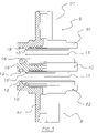
- FIG. 1 In more detail, in the embodiment illustrated in FIG.
- FIG. 2 partially shows a front panel of the medical apparatus 4 , which exhibits a seating predisposed for removable connection with an end connector of the auxiliary line 2 .
- the hollow body comprises a first end portion 8 , a second end portion 9 opposite the first end portion 8 , and a third intermediate portion 10 interpositioned between the two end portions 8 and 9 .
- Each of the three portions, 8 , 9 and 10 is made of a rigid plastic material (in the illustrated embodiment PETG), and is in a single piece and manufactured by plastic moulding.
- the first end portion 8 has a first tubular connector 81 , which defines the inlet 5 of the hollow body, destined to be connected with a fluid line connected during operation to the extracorporeal fluid transport circuit.
- the fluid line (auxiliary line 2 ) comprises a flexible tube, made of a plastic material, joined to the first tubular connector 81 by force-fitting and gluing.
- the second end portion 9 has a second tubular connector 91 , which defines the outlet 6 of the hollow body, and which is in gas communication with the first tubular connector 81 through an internal cavity 11 of the hollow body; the second tubular connector 91 is destined to be connected to a fluid line which during operation is connected to the pressure gauge of the medical apparatus 4 .
- the two tubular connectors 81 and 91 are reciprocally coaxial.
- the two end portions 8 and 9 each have a flanged part 82 and 92 which exhibits, as will be better described herein below, at least one permanent join zone with the third intermediate portion 10 .
- the third intermediate portion 10 is plate-shaped, centrally open, coaxial with the two end portions 8 and 9 , and has an axial dimension which is smaller than the radial dimensions thereof.
- the central opening of the third intermediate portion 10 allows passage of gas.
- the third intermediate portion 10 is, in substance, a flanged union element between the two end portions 8 and 9 .
- the axial dimension of the flanged element is about the same size (not more than two or three times bigger) as the axial dimension of the flanged parts 82 , 92 of the first and second end portions 8 and 9 .
- the third intermediate portion 10 is coupled on a first side thereof to the first end portion 8 along an annular union zone 102 and is coupled on a second side thereof, opposite to the first side, to the second end portion 9 , along an annular union zone 104 .
- the annular union zones 102 and 104 are permanent coupling zones, and are coaxial one to another and have about the same diameter, and in the illustrated embodiment are constituted by ultrasonic weld zones.
- the third intermediate portion 10 is a press-formed single piece plastic element.
- the third intermediate portion 10 has a prevalently radially-extending development, rather than axially-extending.
- the third intermediate portion 10 is more greatly developed in breadth rather than in length, where for length we intend the direction of the longitudinal axis of the hollow body.
- the device comprises a first filter membrane 12 , with hydrophobic properties, contained in the hollow body and defining, in the cavity II of the hollow body, a first anti-contamination aseptic barrier, arranged transversally between the first end portion 8 and the third intermediate portion 10 .
- a second filter membrane 13 is housed in the hollow body, which second membrane has hydrophobic properties and defines, in the cavity 11 of the hollow body, a second anti-contamination aseptic barrier, arranged transversally between the second end portion 9 and the third intermediate portion 10 .
- the peripheral sealed edge of the first filter membrane 12 is pressed, at the annular seal zone 101 , between the first end portion 8 and the third intermediate portion 10 .
- the peripheral sealed edge of the second filter membrane 13 is pressed, at the annular seal zone 103 , between the second end portion 9 and the third intermediate portion 10 .
- the two annular seal zones 101 and 103 are coaxial and have about the same diameter. Further, the annular seal zones, 101 and 103 , are coaxial to the annular union zones 102 and 104 , and have a smaller diameter than the annular union zones 102 and 104 .
- Both the first membrane 12 and the second membrane 13 are formed by at least two layers, one an operating filtering layer, made of polyetetrafluoroethylene and facing the inlet 5 of the hollow body, and a support layer, made of non-woven polyester and facing the outlet 6 of the hollow body.
- Both the first membrane 12 and the second membrane 13 are filter membranes allowing passage of air, so that changes in pressure on one side of each membrane are transmitted to the opposite side, to which a pressure-sensitive device is connected.
- both the first membrane 12 and the second membrane 13 are gas-permeable to enable transmission of a pressure signal through the protection device 1 , from the inlet 5 to the outlet 6 , i.e. from the extracorporeal circuit 3 to the pressure gauge of the medical apparatus 4 , without determining any relevant loss of head; the pressure measured by the medical apparatus 4 thus corresponds to the effective pressure in the extracorporeal circuit 3 .
- each filter membrane 12 and 13 blocks non-sterile particles and prevents the passage of contaminating agents from one side to the other of the membrane.
- the central part of the first membrane 12 faces the central part of the second membrane 13 in a central gas passage zone internally of the hollow body, comprised between the inlet 5 and the outlet 6 of the hollow body.
- the first portion of end 8 has an internal surface which faces and is parallel to the first membrane 12 and delimits the internal cavity 11 of the hollow body.
- the internal surface is arranged perpendicular to the axis of the hollow body and centrally exhibits an opening for fluid passage.
- a plurality of reliefs 14 are fashioned from the internal surface, which reliefs 14 define a striker surface for the first membrane 12 .
- the second end portion 9 has an internal surface, facing and parallel to the second membrane 13 and delimiting the cavity 11 internally of the hollow body.
- the internal surface is perpendicular to the axis of the hollow body and centrally exhibits an opening for fluid passage.
- a plurality of reliefs 15 are fashioned from this surface and define a striker surface for the second membrane 13 .
- the third intermediate portion 10 has, on two opposite sides, two internal surfaces which delimit the internal cavity 11 of the hollow body, each of which is perpendicular to the axis of the hollow body and centrally exhibits an opening for fluid passage.
- a plurality of reliefs 16 is fashioned from a first internal surface, facing and parallel to the first membrane 12 on an opposite side thereof with respect to the internal surface of the first end portion 8 .
- the plurality of reliefs 16 defines a striker surface for the first membrane 12 .
- a further plurality of reliefs 17 are fashioned from a second internal surface, opposite to the first internal surface and facing and parallel to the second membrane 13 , on an opposite side to the internal surface of the second end portion 9 .
- the plurality of reliefs 17 define a striker surface for the second membrane 13 .
- the above-cited pluralities of reliefs 14 , 15 , 16 and 17 fashioned on each of the three portions 8 , 9 and 10 of the hollow body, are fashioned as ribs arranged tangentially, with reference to the longitudinal axis of the hollow body, to define a plurality of tangential channels communicating with a central zone of the cavity 11 of the hollow body, through one or more radial channels defined by the reliefs (as can be seen in FIGS. 5 , 9 , 13 and 16 ).
- annular liquid-seal zones 101 and 103 which guarantee the aseptic barrier provided by each membrane 12 and 13 , are also zones where the peripheral edges of the membranes 12 and 13 , squeezed between the first end portion 8 and the third intermediate portion 10 , and the third intermediate portion 10 and the second end portion 9 —are solidly constrained to the hollow body.
- the described device is manufactured using a process which includes a preliminary stage of preparation, by means of plastic press-forming, of the three portions 8 , 9 and 10 of the hollow body, in which the annular. union zones 102 and 104 , predisposed for permanent connection by plastic ultrasonic welding, comprise annular welding projections 18 with tapered ends, in particular with triangular meridian sections.
- the annular welding projections 18 present on one or more of the various portions of the hollow body, are coupled with annular surfaces 19 specially shaped to receive the annular welding projections 18 and situated on another, facing portion of the hollow body.
- the first end portion 8 exhibits, in the union zone 102 , an annular welding projection 18 which corresponds to a flat annular surface 19 lying in an annular recess on the third intermediate portion 10 . Further, the first end portion 8 exhibits, in the annular seal zone 101 , more internally and having a smaller diameter than the union zone 102 , a flat annular surface 19 ′, corresponding with a sealing annular crushing projection 18 ′ located on the third intermediate portion 10 .
- the second end portion 9 exhibits, in the union zone 104 , in an annular recess, a flat annular surface 19 corresponding with an annular welding zone 18 located on the third intermediate portion 10 ; further, the second end portion 9 exhibits, in the seal zone 103 , more internal and having a smaller diameter than the union zone 104 , a sealing annular crushing projection 18 ′, corresponding with a flat annular surface 19 ′ located on the third intermediate zone 10 .
- the process also includes a preliminary stage of preparation of the hydrophobic filter membranes 12 and 13 , by transversal cutting of a continuous belt of material.
- the three portions 8 , 9 and 10 and the two filter membranes 12 and 13 are arranged in a group, with the third portion 10 interpositioned between the first and second end portions 8 and 9 , the first membrane 12 being arranged transversally between the first and the third portions 8 and 10 , and the second membrane 13 being arranged transversally between the third and the second portions 10 and 9 , causing the annular welding projections 18 and the sealing crushing projections 18 ′ to contact the corresponding annular surfaces 19 and 19 ′, and 1 o interpositioning the perimeter edges of the membranes 12 and 13 between the annular seal zones 101 and 103 .
- This grouped configuration, which precedes the welding stage, is illustrated in FIG. 4 .
- the process at this point includes solidly uniting the three portions 8 , 9 , 10 of the hollow body together, as well as the two hydrophobic protective filter membranes 12 and 13 , through a simultaneous solid connection thereof, along the annular union zones 102 and 104 .
- This simultaneous and solid connection comprises, in the illustrated embodiment, a use of ultrasonic energy which, as is known, leads to localized fusion of the annular welding projections 18 .
- the ultrasonic energy causes a partial fusion, or at least a partial softening, of the material the sealing crushing projections 18 ′ are made of.
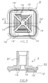
- each membrane 12 and 13 has, observed in plan view, at least one straight perimeter side.
- each membrane 12 and 13 has, seen in plan view, at least a first pair of opposite perimeter sides which are parallel one to another.
- Each membrane 12 and 13 has, seen in plan view, a second pair of opposite perimeter sides, and in even more detail, each membrane 12 and 13 has, once more seen in plan view, a rectangular shape, which, more specifically, in the illustrated embodiment is square.
- At least the two annular seal zones 101 and 103 prevalently follow the shape of the liquid-sealed membrane perimeter zone, and include rounded zones at the corners, to avoid creating union zones with live edges.
- the annular union zones 102 and 104 which are arranged coaxially and more peripherally with respect to the annular seal zones 101 and 103 , are more or less of the same shape, but wider, as the annular seal zones 101 and 103 .
- the annular union zones 102 and 104 have a rectangular shape, in fact are square, and have rounded corners.
- membranes having, in plan view, a polygonal shape which is different to what is described above for example a non-equilateral rectangular shape, or a non-rectangular quadrilateral shape, or a regular polygon with more than four sides, and so on. It would also be possible to use membranes having a shape which is close to a square shape, but having sides which are not straight but rather slightly curved, with non-live but rounded edges.
- All the membrane shapes described here have in common the fact of the presence of at least one perimeter side, having a curvature diameter which is greater than the lateral dimension of the membrane, the lateral dimension being considered in a perpendicular direction to the side itself. Where the perimeter side is straight, the corresponding diameter of curvature can be considered, from a purely mathematical point of view, to be of an infinite length, and thus, from a practical point of view, without doubt longer than the lateral dimension of the membrane.
- the square shape, and the shapes described above, which all include at least one straight or nearly straight perimeter side, have, with respect to the usual circular shape, the advantage of offering a greater active membrane surface, in conditions of a same lateral dimension, with a consequent reduction in the drop of pressure and a better transmission of the pressure signal across the device, without losing any efficiency as far as the protective function is concerned. Further, by using membranes with at least one straight or nearly-straight perimeter side, membranes can be produced by a transversal cutting of a continuous tape, with a considerable ensuing reduction, possibly even a complete elimination, of waste of material.
- a further advantage of the above-described device, with a non-circular peripheral shape, is that the operator can grip the device more easily and handle it more comfortably.
- the above-described advantages can be obtained by using a membrane having a plan shape delimited by a determined perimeter border, in which the circle of maximum possible diameter within the border has a total area which is smaller than the area of the membrane; in other words, the membrane is larger than the maximum diameter circle that can be drawn within it.
- FIGS. from 19 to 22 four different embodiments of the double-membrane protection device of the invention are illustrated, which differ among themselves in the tubular connections: the first device ( FIG. 19 ) exhibits two smooth connectors, for coupling to the tubes by force-fitting and gluing; the second device ( FIG. 20 ) exhibits a smooth connector and a female Luer connector; the third device ( FIG. 21 ) exhibits a smooth connector and a male Luer connector; the fourth device (FIG. 22 ) exhibits a female Luer connector and a male Luer connector.
- a protection device 1 ′ comprises a single hydrophobic protective membrane 12 ′, having a plan shape which is the same as what is described above, i.e. with one or more straight perimeter sides, or nearly so, or, in more general terms, having a surface areas which is greater than a maximum circle which can be drawn therein.
- the third intermediate portion is absent, and the only protective membrane 12 ′ is arranged transversally between the first and the second end portions 8 ′ and 9 ′.
- the two end portions 8 and 9 are already set up and structured to be directly couplable to each other, with the interpositioning of a single filter membrane. Therefore, in FIG. 1 ′ of FIG. 23 , the two portions 8 ′ and 9 ′ of the hollow body are identical to the two end portions 8 and 9 or the device 1 of figures from 1 to 18 , and the filter membrane 12 ′ is identical to the filter membrane 12 or 13 .
- the device 1 ′ of FIG. 23 having a single membrane, has the advantage of providing efficient transmission of the pressure, in terms of parity of lateral dimensions, and easy grip and handling.
Abstract
Description
Claims (30)
Priority Applications (2)
| Application Number | Priority Date | Filing Date | Title |
|---|---|---|---|
| US10/804,147 US7175697B2 (en) | 2003-03-21 | 2004-03-19 | Device for protecting medical apparatus |
| US11/635,520 US7621983B2 (en) | 2003-03-21 | 2006-12-08 | Transduction-protection device |
Applications Claiming Priority (4)
| Application Number | Priority Date | Filing Date | Title |
|---|---|---|---|
| IT000079A ITMO20030079A1 (en) | 2003-03-21 | 2003-03-21 | DEVICE TO PROTECT MEDICAL EQUIPMENT |
| ITMO2003A000079 | 2003-03-21 | ||
| US48040303P | 2003-06-23 | 2003-06-23 | |
| US10/804,147 US7175697B2 (en) | 2003-03-21 | 2004-03-19 | Device for protecting medical apparatus |
Related Child Applications (1)
| Application Number | Title | Priority Date | Filing Date |
|---|---|---|---|
| US11/635,520 Continuation US7621983B2 (en) | 2003-03-21 | 2006-12-08 | Transduction-protection device |
Publications (2)
| Publication Number | Publication Date |
|---|---|
| US20040237785A1 US20040237785A1 (en) | 2004-12-02 |
| US7175697B2 true US7175697B2 (en) | 2007-02-13 |
Family
ID=33458190
Family Applications (2)
| Application Number | Title | Priority Date | Filing Date |
|---|---|---|---|
| US10/804,147 Active 2025-03-05 US7175697B2 (en) | 2003-03-21 | 2004-03-19 | Device for protecting medical apparatus |
| US11/635,520 Active 2025-01-29 US7621983B2 (en) | 2003-03-21 | 2006-12-08 | Transduction-protection device |
Family Applications After (1)
| Application Number | Title | Priority Date | Filing Date |
|---|---|---|---|
| US11/635,520 Active 2025-01-29 US7621983B2 (en) | 2003-03-21 | 2006-12-08 | Transduction-protection device |
Country Status (1)
| Country | Link |
|---|---|
| US (2) | US7175697B2 (en) |
Cited By (10)
| Publication number | Priority date | Publication date | Assignee | Title |
|---|---|---|---|---|
| US20050279692A1 (en) * | 2004-06-22 | 2005-12-22 | Luca Caleffi | Transducer-protector device for medical apparatus |
| US20080053906A1 (en) * | 2006-09-04 | 2008-03-06 | Katsunori Kawai | Protective filter for extracorporeal circulation circuit pressure monitor |
| US20080221499A1 (en) * | 2007-03-06 | 2008-09-11 | Baxter International, Inc. | Transducer protector |
| US20130224866A1 (en) * | 2006-07-20 | 2013-08-29 | Baxter Healthcare S.A. | Medical fluid access device with antiseptic indicator |
| US9328969B2 (en) | 2011-10-07 | 2016-05-03 | Outset Medical, Inc. | Heat exchange fluid purification for dialysis system |
| US9402945B2 (en) | 2014-04-29 | 2016-08-02 | Outset Medical, Inc. | Dialysis system and methods |
| US9545469B2 (en) | 2009-12-05 | 2017-01-17 | Outset Medical, Inc. | Dialysis system with ultrafiltration control |
| US11534537B2 (en) | 2016-08-19 | 2022-12-27 | Outset Medical, Inc. | Peritoneal dialysis system and methods |
| US11724013B2 (en) | 2010-06-07 | 2023-08-15 | Outset Medical, Inc. | Fluid purification system |
| US11951241B2 (en) | 2022-11-28 | 2024-04-09 | Outset Medical, Inc. | Peritoneal dialysis system and methods |
Families Citing this family (25)
| Publication number | Priority date | Publication date | Assignee | Title |
|---|---|---|---|---|
| US7516665B2 (en) * | 2003-12-23 | 2009-04-14 | Jms North America Corporation | Double membrane transducer protector |
| US7069788B2 (en) * | 2003-12-23 | 2006-07-04 | Jms North America Corp. | Double membrane transducer protector |
| US20060102555A1 (en) * | 2004-11-15 | 2006-05-18 | Jordan Lowell S | Filter connector |
| EP1728526B1 (en) * | 2005-06-03 | 2012-12-26 | Fresenius Medical Care Deutschland GmbH | System for monitoring the pressure in a blood line and a device to be used with such a system |
| US7871391B2 (en) | 2005-10-21 | 2011-01-18 | Fresenius Medical Care Holdings, Inc. | Extracorporeal fluid circuit |
| US8137303B2 (en) * | 2006-05-08 | 2012-03-20 | Becton, Dickinson And Company | Vascular access device cleaning status indication |
| EP3150238B1 (en) | 2007-09-19 | 2018-03-14 | Fresenius Medical Care Holdings, Inc. | Dialysis systems and related components |
| CN101868262B (en) * | 2007-09-19 | 2013-11-06 | 弗雷塞尼斯医疗保健控股公司 | Safety vent structure for extracorporeal circuit |
| US8663463B2 (en) * | 2009-02-18 | 2014-03-04 | Fresenius Medical Care Holdings, Inc. | Extracorporeal fluid circuit and related components |
| US8876943B2 (en) * | 2009-09-14 | 2014-11-04 | Random Technologies Llc | Apparatus and methods for changing the concentration of gases in liquids |
| US8500994B2 (en) * | 2010-01-07 | 2013-08-06 | Fresenius Medical Care Holdings, Inc. | Dialysis systems and methods |
| US9220832B2 (en) | 2010-01-07 | 2015-12-29 | Fresenius Medical Care Holdings, Inc. | Dialysis systems and methods |
| US9498107B2 (en) | 2010-08-06 | 2016-11-22 | Carefusion 2200, Inc. | Clamping system |
| US8776800B2 (en) | 2010-09-30 | 2014-07-15 | Carefusion 2200, Inc. | Sterile drape having multiple drape interface mechanisms |
| US20120065472A1 (en) * | 2010-09-11 | 2012-03-15 | Mark Doyle | Protective sheath |
| US8740883B2 (en) | 2010-09-30 | 2014-06-03 | Carefusion 2200, Inc. | Detachable handle mechanism for use in instrument positioning |
| US8640706B2 (en) | 2010-09-30 | 2014-02-04 | Carefusion 2200, Inc. | Interface mechanism between a drape and a handle |
| ITMO20100318A1 (en) * | 2010-11-09 | 2012-05-10 | Lucomed S P A | FITTING FOR THE CONNECTION OF A PRESSURE TRANSDUCER TO A HEMODIALYSIS MACHINE. |
| US8506684B2 (en) | 2010-12-15 | 2013-08-13 | Fresenius Medical Care Holdings, Inc. | Gas release devices for extracorporeal fluid circuits and related methods |
| US9375524B2 (en) | 2011-06-03 | 2016-06-28 | Fresenius Medical Care Holdings, Inc. | Method and arrangement for venting gases from a container having a powdered concentrate for use in hemodialysis |
| DE102012018078A1 (en) * | 2012-09-13 | 2014-03-13 | Fresenius Medical Care Deutschland Gmbh | Pressure transducer protection device for blood tube systems |
| US9433721B2 (en) | 2013-06-25 | 2016-09-06 | Fresenius Medical Care Holdings, Inc. | Vial spiking assemblies and related methods |
| US9974942B2 (en) | 2015-06-19 | 2018-05-22 | Fresenius Medical Care Holdings, Inc. | Non-vented vial drug delivery |
| US9945838B2 (en) | 2015-12-17 | 2018-04-17 | Fresenius Medical Care Holdings, Inc. | Extracorporeal circuit blood chamber having an integrated deaeration device |
| CN209917010U (en) * | 2018-04-03 | 2020-01-10 | 东莞永胜医疗制品有限公司 | Improved moisture dissipating cartridge and breathing circuit and breathing system incorporating same |
Citations (19)
| Publication number | Priority date | Publication date | Assignee | Title |
|---|---|---|---|---|
| US4314480A (en) | 1980-07-14 | 1982-02-09 | Baxter Travenol Laboratories, Inc. | Venous pressure isolator |
| DE3126850A1 (en) | 1980-07-18 | 1982-03-11 | Sartorius GmbH, 3400 Göttingen | Membrane filter blank for membrane flat filter apparatuses |
| US4493693A (en) | 1982-07-30 | 1985-01-15 | Baxter Travenol Laboratories, Inc. | Trans-membrane pressure monitoring system |
| GB2168263A (en) | 1984-12-13 | 1986-06-18 | Sartorius Gmbh | Disposable filter |
| EP0536297A1 (en) | 1990-06-29 | 1993-04-14 | Coulter Corporation | Process and apparatus for removal of dna and viruses |
| US5269917A (en) * | 1992-02-28 | 1993-12-14 | Millipore Corporation | Filtration apparatus having stress relief groove |
| EP0652018A2 (en) | 1993-11-09 | 1995-05-10 | INDUSTRIE BORLA S.p.A. | Transducer-protector device for biomedical haemodialysis lines |
| US5443723A (en) * | 1994-02-22 | 1995-08-22 | Millipore Corporation | Membrane support and sealing apparatus |
| US5458586A (en) | 1994-11-14 | 1995-10-17 | Pall Corporation | Universal connector for vacuum systems |
| IT1270858B (en) | 1993-05-29 | 1997-05-13 | Borla Ind | TRANSDUCER-PROTECTOR DEVICE FOR BIOMEDICAL HEMODIALYSIS LINES |
| ITTO961000A1 (en) | 1996-12-10 | 1998-06-10 | Borla Ind | TRANSDUCER-PROTECTOR DEVICE FOR BIOMEDICAL LINES OF AMODIALS - AND PROCEDURE FOR ITS MANUFACTURE |
| DE19816871A1 (en) | 1998-04-16 | 1999-10-21 | Sartorius Gmbh | Disposable filter cartridge for medical and domestic use |
| EP0878628B1 (en) | 1997-05-15 | 2000-04-12 | Filtertek B.V. | Pressure transmission device |
| US6086762A (en) | 1997-06-27 | 2000-07-11 | Industrie Borla S.P.A. | Transducer-protector device for biomedical haemodialysis lines |
| EP1097725A2 (en) | 1999-11-08 | 2001-05-09 | GVS S.r.l. | Transducer protection device, particularly for hemodialysis processes |
| US20030040687A1 (en) | 2001-08-24 | 2003-02-27 | Kci Licensing, Inc | Vacuum assisted tissue treatment system |
| US6602325B1 (en) * | 1999-10-21 | 2003-08-05 | Ati Properties, Inc. | Fluid separation assembly |
| US20040173516A1 (en) | 2003-03-04 | 2004-09-09 | Industrie Borla S.P.A | Transducer-protector device for biomedical haemodialysis lines |
| US20050132826A1 (en) | 2003-12-23 | 2005-06-23 | Ludwig Teugels | Double membrane transducer protector |
Family Cites Families (4)
| Publication number | Priority date | Publication date | Assignee | Title |
|---|---|---|---|---|
| US40687A (en) * | 1863-11-24 | Improvement in revolving fire-arms | ||
| US4501663A (en) * | 1979-11-05 | 1985-02-26 | Millipore Corporation | Filter cartridges and methods and components for making them |
| SE9402720D0 (en) | 1994-08-15 | 1994-08-15 | Gambro Ab | Insert for pressure transducer |
| JP2002071494A (en) | 2000-08-31 | 2002-03-08 | Yokogawa Electric Corp | Differential pressure and pressure gauge |
-
2004
- 2004-03-19 US US10/804,147 patent/US7175697B2/en active Active
-
2006
- 2006-12-08 US US11/635,520 patent/US7621983B2/en active Active
Patent Citations (27)
| Publication number | Priority date | Publication date | Assignee | Title |
|---|---|---|---|---|
| US4314480A (en) | 1980-07-14 | 1982-02-09 | Baxter Travenol Laboratories, Inc. | Venous pressure isolator |
| DE3126850A1 (en) | 1980-07-18 | 1982-03-11 | Sartorius GmbH, 3400 Göttingen | Membrane filter blank for membrane flat filter apparatuses |
| US4493693A (en) | 1982-07-30 | 1985-01-15 | Baxter Travenol Laboratories, Inc. | Trans-membrane pressure monitoring system |
| GB2168263A (en) | 1984-12-13 | 1986-06-18 | Sartorius Gmbh | Disposable filter |
| EP0536297A1 (en) | 1990-06-29 | 1993-04-14 | Coulter Corporation | Process and apparatus for removal of dna and viruses |
| US5269917A (en) * | 1992-02-28 | 1993-12-14 | Millipore Corporation | Filtration apparatus having stress relief groove |
| IT1270858B (en) | 1993-05-29 | 1997-05-13 | Borla Ind | TRANSDUCER-PROTECTOR DEVICE FOR BIOMEDICAL HEMODIALYSIS LINES |
| EP0652018A2 (en) | 1993-11-09 | 1995-05-10 | INDUSTRIE BORLA S.p.A. | Transducer-protector device for biomedical haemodialysis lines |
| US5500003A (en) | 1993-11-09 | 1996-03-19 | Industrie Borla, S.P.A. | Transducer-protector device for biomedical haemodialysis lines |
| US5603792A (en) | 1993-11-09 | 1997-02-18 | Industrie Borla S.P.A. | Method of making a transducer-protector device for biomedical haemodialysis lines |
| US5443723A (en) * | 1994-02-22 | 1995-08-22 | Millipore Corporation | Membrane support and sealing apparatus |
| US5458586A (en) | 1994-11-14 | 1995-10-17 | Pall Corporation | Universal connector for vacuum systems |
| ITTO961000A1 (en) | 1996-12-10 | 1998-06-10 | Borla Ind | TRANSDUCER-PROTECTOR DEVICE FOR BIOMEDICAL LINES OF AMODIALS - AND PROCEDURE FOR ITS MANUFACTURE |
| US6168653B1 (en) | 1997-05-15 | 2001-01-02 | Filtertek, Inc | Pressure transmission apparatus |
| US6506237B2 (en) | 1997-05-15 | 2003-01-14 | Filtertek Inc. | Pressure transmission apparatus |
| EP0878628B1 (en) | 1997-05-15 | 2000-04-12 | Filtertek B.V. | Pressure transmission device |
| EP0887085B1 (en) | 1997-06-27 | 2001-11-28 | Industrie Borla SpA | Transducer-protector device for biomedical haemodialysis lines |
| US6086762A (en) | 1997-06-27 | 2000-07-11 | Industrie Borla S.P.A. | Transducer-protector device for biomedical haemodialysis lines |
| DE19816871A1 (en) | 1998-04-16 | 1999-10-21 | Sartorius Gmbh | Disposable filter cartridge for medical and domestic use |
| WO1999054022A1 (en) | 1998-04-16 | 1999-10-28 | Sartorius Ag | Filtration unit for removing contaminants from fluids |
| US6602325B1 (en) * | 1999-10-21 | 2003-08-05 | Ati Properties, Inc. | Fluid separation assembly |
| EP1097725A2 (en) | 1999-11-08 | 2001-05-09 | GVS S.r.l. | Transducer protection device, particularly for hemodialysis processes |
| US6536278B1 (en) | 1999-11-08 | 2003-03-25 | Gvs S.R.L. | Transducer protection device, particularly for hemodialysis processes |
| US20030040687A1 (en) | 2001-08-24 | 2003-02-27 | Kci Licensing, Inc | Vacuum assisted tissue treatment system |
| US20040173516A1 (en) | 2003-03-04 | 2004-09-09 | Industrie Borla S.P.A | Transducer-protector device for biomedical haemodialysis lines |
| US20050132826A1 (en) | 2003-12-23 | 2005-06-23 | Ludwig Teugels | Double membrane transducer protector |
| EP1547630A1 (en) | 2003-12-23 | 2005-06-29 | Ludwig Teugels | Double membrane transducer protector |
Non-Patent Citations (2)
| Title |
|---|
| International Preliminary Report on Patentability for International Application No. PCT/IB2004/000763. |
| International Search Report for International Application No. PCT/IB2004/000763. |
Cited By (16)
| Publication number | Priority date | Publication date | Assignee | Title |
|---|---|---|---|---|
| US7520919B2 (en) * | 2004-06-22 | 2009-04-21 | Gambro Lundia Ab | Transducer-protector device for medical apparatus |
| US20050279692A1 (en) * | 2004-06-22 | 2005-12-22 | Luca Caleffi | Transducer-protector device for medical apparatus |
| US20130224866A1 (en) * | 2006-07-20 | 2013-08-29 | Baxter Healthcare S.A. | Medical fluid access device with antiseptic indicator |
| US20080053906A1 (en) * | 2006-09-04 | 2008-03-06 | Katsunori Kawai | Protective filter for extracorporeal circulation circuit pressure monitor |
| US7833321B2 (en) * | 2006-09-04 | 2010-11-16 | Nipro Corporation | Protective filter for extracorporeal circulation circuit pressure monitor |
| US20080221499A1 (en) * | 2007-03-06 | 2008-09-11 | Baxter International, Inc. | Transducer protector |
| US7892428B2 (en) | 2007-03-06 | 2011-02-22 | Baxter International Inc. | Transducer protector |
| US9545469B2 (en) | 2009-12-05 | 2017-01-17 | Outset Medical, Inc. | Dialysis system with ultrafiltration control |
| US11724013B2 (en) | 2010-06-07 | 2023-08-15 | Outset Medical, Inc. | Fluid purification system |
| US9328969B2 (en) | 2011-10-07 | 2016-05-03 | Outset Medical, Inc. | Heat exchange fluid purification for dialysis system |
| US9402945B2 (en) | 2014-04-29 | 2016-08-02 | Outset Medical, Inc. | Dialysis system and methods |
| US9579440B2 (en) | 2014-04-29 | 2017-02-28 | Outset Medical, Inc. | Dialysis system and methods |
| US11305040B2 (en) | 2014-04-29 | 2022-04-19 | Outset Medical, Inc. | Dialysis system and methods |
| US9504777B2 (en) | 2014-04-29 | 2016-11-29 | Outset Medical, Inc. | Dialysis system and methods |
| US11534537B2 (en) | 2016-08-19 | 2022-12-27 | Outset Medical, Inc. | Peritoneal dialysis system and methods |
| US11951241B2 (en) | 2022-11-28 | 2024-04-09 | Outset Medical, Inc. | Peritoneal dialysis system and methods |
Also Published As
| Publication number | Publication date |
|---|---|
| US7621983B2 (en) | 2009-11-24 |
| US20040237785A1 (en) | 2004-12-02 |
| US20070084779A1 (en) | 2007-04-19 |
Similar Documents
| Publication | Publication Date | Title |
|---|---|---|
| US7175697B2 (en) | Device for protecting medical apparatus | |
| EP1605990B1 (en) | A device for protecting medical apparatus. | |
| CN1200743C (en) | Wound suction device with multi-lumen connector | |
| JP3637495B2 (en) | Medical container port | |
| US6830685B2 (en) | Filtering device with associated sealing design and method | |
| KR101693954B1 (en) | Hollow-fiber membrane module, process for producing hollow-fiber membrane module, and hollow-fiber membrane unit equipped with hollow-fiber membrane module | |
| CN112118876B (en) | Multifunctional cap for fluid port on medical device | |
| US6427846B1 (en) | Plastic filtration unit bonded by an L-shaped plastic melt | |
| US20190105608A1 (en) | Hollow fiber membrane module and manufacturing method therefor | |
| US20050279692A1 (en) | Transducer-protector device for medical apparatus | |
| TWI600443B (en) | Hollow fiber membrane blood purifier | |
| JP2007175566A (en) | Hollow fiber membrane module | |
| JPH03118807A (en) | Color-marked throwaway filter holder | |
| US7060183B1 (en) | Unit for filtering a fluid | |
| CN102405070A (en) | Device, external functional device and treatment device for treating medical fluids | |
| JP4038547B2 (en) | Improvement of blood filter, blood collection processing system and method | |
| JP4727974B2 (en) | Transducer filter and extracorporeal circuit | |
| CN213911675U (en) | Pressure sensor | |
| JP2001129079A (en) | Transducer protective filter for dialysis and its manufacturing method | |
| EP1300128A1 (en) | Blood processing filter | |
| JPS61240964A (en) | Body fluid treating device and its production | |
| JP2009240499A (en) | Hemodiafiltration module | |
| CN214807275U (en) | Novel PP dialyzer | |
| CN210501519U (en) | Hemodialysis machine cleaning and disinfecting stick | |
| JP2004337287A (en) | Transducer filter |
Legal Events
| Date | Code | Title | Description |
|---|---|---|---|
| AS | Assignment |
Owner name: GAMBRO LUNDIA AB, SWEDEN Free format text: ASSIGNMENT OF ASSIGNORS INTEREST;ASSIGNOR:GAMBRO DASCO S.P.A.;REEL/FRAME:015136/0434 Effective date: 20030310 Owner name: GAMBRO DASCO S.P.A., ITALY Free format text: ASSIGNMENT OF ASSIGNORS INTEREST;ASSIGNOR:NERI, ROBERTO;REEL/FRAME:015146/0098 Effective date: 20030305 |
|
| STCF | Information on status: patent grant |
Free format text: PATENTED CASE |
|
| CC | Certificate of correction | ||
| AS | Assignment |
Owner name: CITICORP TRUSTEE COMPANY LIMITED, UNITED KINGDOM Free format text: IP SECURITY AGREEMENT SUPPLEMENT;ASSIGNOR:GAMBRO LUNDIA AB;REEL/FRAME:022714/0702 Effective date: 20090331 Owner name: CITICORP TRUSTEE COMPANY LIMITED,UNITED KINGDOM Free format text: IP SECURITY AGREEMENT SUPPLEMENT;ASSIGNOR:GAMBRO LUNDIA AB;REEL/FRAME:022714/0702 Effective date: 20090331 |
|
| FPAY | Fee payment |
Year of fee payment: 4 |
|
| AS | Assignment |
Owner name: GAMBRO LUNDIA AB, COLORADO Free format text: RELEASE OF SECURITY INTEREST IN PATENTS;ASSIGNOR:CITICORP TRUSTEE COMPANY LIMITED, AS SECURITY AGENT;REEL/FRAME:027456/0050 Effective date: 20111207 |
|
| FPAY | Fee payment |
Year of fee payment: 8 |
|
| MAFP | Maintenance fee payment |
Free format text: PAYMENT OF MAINTENANCE FEE, 12TH YEAR, LARGE ENTITY (ORIGINAL EVENT CODE: M1553) Year of fee payment: 12 |